Table of Contents
Advertisement
User'
User' s s s s s
User'
User'
User'
Manual
Manual
Manual
Manual
Manual
nVIDIA nForce
nVIDIA
nVIDIA
nForce2 2 2 2 2 Ultra 400
nForce
nForce
nVIDIA
nVIDIA
nForce
for AMD Socket A A A A A processor
for AMD Socket
for AMD Socket
for AMD Socket
for AMD Socket
TRADEMARK
All products and company names are trademarks or registered
trademarks of their respective holders.
These specifications are subject to change without notice.
Ultra 400 mainboard
Ultra 400
Ultra 400
Ultra 400
processor
processor
processor
processor
Manual Revision 1.0
July 05, 2004
mainboard
mainboard
mainboard
mainboard
Advertisement
Table of Contents

Related Manuals for Nvidia NFORCE2 ULTRA 400 400


Summary of Contents for Nvidia NFORCE2 ULTRA 400 400
- Page 1 User’ User’ s s s s s User’ User’ User’ Manual Manual Manual Manual Manual nVIDIA nForce nVIDIA nVIDIA nForce2 2 2 2 2 Ultra 400 nForce nForce nVIDIA nVIDIA nForce for AMD Socket A A A A A processor...
- Page 2 DISCLAIMER OF WARRANTIES: THERE ARE NO WARRANTIES WHICH EXTEND BEYOND THE DESCRIPTION ON THE FACE OF THE MANUFACTURER LIMITED WARRANTY. THE MANUFACTURER EXPRESSLY EXCLUDES ALL OTHER WARRANTIES, EXPRESS OR IMPLIED, REGARDING ITS PRODUCTS; INCLUDING ANY IMPLIED WARRANTIES OF MERCHANTABILITY, FITNESS FOR A PARTICULAR PURPOSE OR NONINFRINGEMENT.
- Page 3 80 Port Frequently Asked Questions Below is a list of some basic POST Codes, possible problems and solutions. For more detailed information about POST Codes, refer to Appendix C in this manual. P O ST C O D E P r o bl e m FFh o r CFh 1 .B IO S c hip inse rte d inc o rre c tly...
-
Page 4: Table Of Contents
Table of Contents Section 1 Introduction Package Contents ... 1- 1 Mainboard Features ... 1- 2 System Block Diagram ... 1- 5 Section 2 Specification Mainboard Specification ... 2- 1 Section 3 Installatio Mainboard Layout ... 3- 1 Easy Installation Procedure ... 3- 2 CPU Insertion ... - Page 5 Supervisor/User Password Setting ... 4- 21 Exit Selecting ... 4- 22 Section 5 S-ATA RAID Configuration Introduction ... 5- 1 NVidia SATA RAID Features ... 5- 3 Enable RAID Function ... 5- 4 Section 6 Driver Installation Easy Driver Installation ... 6- 1 Realtek Sound Manager Quick User guide ...
- Page 6 Page Left Blank...
-
Page 7: Introduction
1-1 Package Contents Contents A. Mainboard B. User’s manual C. Floppy drive cable D. HDD drive cable E. CD (drivers and utilities) F. I/O Shield G. S-ATA data and power cable USER’S MANUAL INTRODUCTION Optional Items H. Game & COM bracket cable I. -
Page 8: Mainboard Features
AGP 8X interface, HyperTransport Link, and is fully compliant with industry standard power management specifications such as ACPI 2.0 and PCI Power Management Interface (PMI) Spec 1.1. For more details about the NVIDIA nForce2 MCPs, please visit the NVIDIA Web site at http://www.nvidia.com. Accelerated Graphics Port (AGP) The AGP slot on the board is compliant with the new AGP 3.0 specification. - Page 9 Introduction 10/100 LAN This mainboard is mounted with an ethernet LAN PHY. It allows the mainboard to connect to a local area network by means of a network hub. Serial ATA Support Serial ATA, an evolutionary replacement for Parallel ATA IDE storage interface .Increases the peak data transfer speed up to 150MB/sec and allows future enhancements to the computing platform.
- Page 10 Introduction Special Features 80 Port An onboard LED-display trouble-shooting device, facilitating user to detect boot-up problems. QuickSPDIF On board SPDIF-out connector for quick connection to multi-channel speakers. Not only removes cable cluttering but also delivers loss-free digital audio to let you enjoy DVD movies and games with crystal clear sound.
-
Page 11: System Block Diagram
Introduction 1-3 System Block Diagram Page 1-5... - Page 12 Introduction Page 1-6...
-
Page 13: Specification
- Athlon XP (1500+ to 3000+) with 266/333MHz Front Side Bus, - Barton (2500+ to 3200+) with 333/400MHz Front Side Bus Chipset nVidia AGPset : nForce2 Ultra 400 + RAID MCP Main Memory Three 184-pin DDR DIMM sockets for 64-bit, Unbuffered, Single/Double-... -
Page 14: Legacy Io Controller
Specification Legacy IO Controller Winbond W83627THF and SIR interface Supports Hardware Monitoring function Audio channel audio with analog and digital output using AC’97 CODEC - AC’97 v2.3 compliant - Supports CD-In, AUX-IN and S/PDIF-in interface - Supports Line-out and Mic-In for front panel - Supports automatic “Jack-sensing”... - Page 15 Four extra USB2.0 ports CD-IN connectors S/PDIF in/out connector IR connector Game port connector Serial Port (COM2) connector S-ATA connectors 1394 connectors (Optional ) Three Fan connectors Front Panel Controller Supports Reset & Soft-Off switches Supports HDD & Power LEDs Supports PC speaker Supports Front Panel Audio connector Expansion Slots...
- Page 16 Specification - Supports complete Asynchronous FSB/Memory and Asynchronous FSB/ AGP, PCI scheme for overclocking CPU Overheating Protection P80P for system debugging Form Factor 305mm x 245 mm ATX size Page 2-4...
-
Page 17: Installation
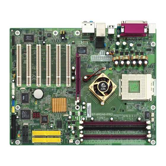
Installation Section 3 INSTALLATION Mainboard Layout <Figure 1> Note: Depending on the model you purchased, some components are optional and may not be available. Page 3-1... -
Page 18: Easy Installation Procedure
Installation Easy Installation Procedure The following must be completed before powering on your new system: 3-1. CPU Installation 3-2. Jumper Settings 3-3. System Memory Configuration 3-4. Expansion Slots 3-5. Device Connectors 3-1 CPU Installation CPU Insertion: (use AMD Athlon <Figure 2> <Figure 3>... - Page 19 <Figure 4> Step 4 Thermal compound and qualified heatsink recommended by AMD are a must to avoid CPU overheat damage. For more information about installing your CPU, please refer to the AMD website article “Socket A AMD processor and Heatsink Installation Guide”...
-
Page 20: Jumper Settings
Installation 3-2 Jumper Settings Page 3-4 JCMOS: Clear CMOS data Jumper If the CMOS data becomes corrupted or you forgot the supervisor or user password, clear the CMOS data to reconfigure the system back to the default values stored in the ROM BIOS. Settings: 1-2: Normal (Default) 2-3: Clear CMOS... -
Page 21: System Memory Configuration
3-3 System Memory Configuration Memory Layout The mainboard accommodates three PC1600/2100/2700/3200 184-pin DIMMs (Dual In- line Memory Modules): • Supports up to 3.0GB of 200/266/333/400MHz DDR SDRAM • Supports up to 3 DDR DIMMs (refer to Table 1) • Supports 64/128/256/512Mb, 1Gb x8 & x16 DRAMs •... -
Page 22: Expansion Slots
Installation 3-4 Expansion Slots AGP Card Installation Caution When installing the AGP card make sure the AGP card edge connector is inserted fully into the slot and the slot clicker is locked. Page 3-6 AGP Slot The mainboard is equipped with an AGP slot. -
Page 23: Device Connectors
3-5 Device Connectors The I/O back panel for this mainboard is shown below. When installing the mainboard into the computer case, use the bundled I/O shield to protect this back panel. Parallel Port PS/2 Mouse PS/2 Keyboard S/PDIF-out Coaxial Jack JPWR_FAN JCPU_FAN JSYS_FAN... - Page 24 Installation IDE1IDE2 IDE1/IDE2 PW12 +12V 5VSB PW-OK Ground Ground +12V +12V Ground Ground Ground Ground Ground PS-ON PW12 Ground Ground 3.3V -12V 3.3V 3.3V Page 3-8 Floppy Controller Connector This connects to the floppy disk drive. IDE1/IDE2:Ultra DMA-100/133 Primary/Secondary IDE Connector This mainboard is equipped with 2 IDE connectors to support up to 4 ATA-133 IDE drives.
- Page 25 In 2-Channel audio mode, Mic-In is shared for both front panel and rear panel. In 6-Channel audio mode, the Mic-In is dedicated for front panel use, and rear panel Mic-In function will switch to Center and Subwoofer support. AUX_IN1 CD_IN1 CFPA: Front Panel Audio Connector When the jumpers are removed this connector can be used for front panel audio.
- Page 26 Installation Page 3-10 SPDIF: Sony/Philips Digital InterFace connector This connector links digital audio between the mainboard and your audio devices, such as CD player, sampler or DAT recorder. It allows the digital transmission of audio data in S/PDIF format. SPDIF_IN SPDIF_OUT GAME1: Game/MIDI connector This port works well with any application that is...
- Page 27 SATA1 / SATA2: Serial ATA Connectors These connectors enable you to connect Serial ATA devices that conform to the Serial ATA specification. SATA2 SATA1 C1394-1 / C1394-2 : (Optional) 400Mbps 1394a (FireWire) Connectors C1394-1 and C1394-2 enable you to connect two IEEE 1394 ports for use with external devices that conform to the IEEE 1394a specification.
- Page 28 Installation CUSB3 CUSB4 Page 3-12 CUSB3/CUSB4: USB 2.0 ports USB2.0 allows data transfer speed up to 480Mbps. This mainboard includes 4 additional USB2.0 ports, identified by two 10-pin connector. If you wish to use the additional USB ports, install the card-edge bracket to the system chassis then insert its cables to this 10-pin connector.
- Page 29 CSPK CFP: Front Panel Connector HD_LED This LED will light up whenever the hard drive is being accessed. PWR_LED This connects to the power button of the system chassis This switch allows you to reboot without having to power off the system thus prolonging the life of the power supply or system.
-
Page 30: Power-On/Off (Remote)
Installation 3-6 Power-On/Off (Remote) This board has a 20-pin ATX and a 4-pin ATX12V power supply connector to support power supplies with Remote On/Off feature. The 4-pin ATX12V connector must be plugged in for the system to operate safely. The chassis power button should be connected to the mainboard front panel PW_ON header (Figure 7). - Page 31 3-8 ACPI S3 (Suspend To RAM) Function This mainboard supports the STR (Suspend To RAM) power management scheme by maintaining the appropriate power states in the DDR SDRAM interface signals. The power source to the DDR SDRAM is kept active during STR (ACPI S3).
-
Page 32: Cpu Overheating Protection
Installation 3-9 CPU Overheating Protection This mainboard is equipped with CPU Overheating Protection. It will automati- cally shutdown the system when CPU temperature reaches approximately 110°C to prevent long term damage to the CPU. When this happens, the speaker produces a sustained beep sound and the system will not be able to power on. This protection is designed through hardware and no BIOS setup is required. -
Page 33: Bios Setup
Main Menu The ROM BIOS contains a built-in Setup program which allows user to modify the basic system configuration and hardware parameters. The modified data is stored in a battery-backed CMOS, so that data will be retained even when the power is turned off. -
Page 34: Standard Cmos Setup
BIOS The main menu displays all the major selection items. Select the item you need to reconfigure. The selection is made by moving the cursor (press any direction (arrow key ) to the item and pressing the ‘Enter’ key. An on-line help message is displayed at the bottom of the screen as the cursor is moved to various items which provides a better understanding of each function. -
Page 35: Advanced Bios Features
4-2 Advanced BIOS Features Selecting the “ADVANCED BIOS FEATURES” option in the CMOS SETUP UTILITY menu allows users to change system related parameters in the displayed menu. This menu shows all of the manufacturer’s default values for the board. Pressing the [F1] key displays a help message for the selected item. Figure 3: BIOS Features Setup Removable Device / Hard Disk / CD-ROM / Network Boot Priority This item allows you to select the removable device/hard disk/CD-ROM/network... -
Page 36: Advanced Chipset Features
BIOS Boot Up Floppy Seek If this item is enabled, it checks the size of the floppy disk drives at start-up time. You don’t need to enable this item unless you have a legacy diskette drive with 360K capacity. Options: Enabled, Disabled. Security Option This category allows you to limit access to the System and Setup, or just to Setup. -
Page 37: Memory Frequency
System Performance This item will help you to configure your system performance, selecting higher performance may cause instability. Options: Optimal, Aggressive, Turbo, Expert. CPU Clock Ratio Use this item to select a multiplier to set the CPU frequency. See FSB Frequency item below for explanation. - Page 38 BIOS Memory Timings For setting DRAM Timing. Options: Optimal, Aggressive, Turbo, Expert. T (RAS) This item specifies the number of clock cycles needed after a bank active command before a precharge can occur (sets the minimum RAS pulse width.). Options: 1 ~ 15. T (RCD) This item sets the timing parameters for the system memory such as the CAS (Column Address Strobe) and RAS (Row Address Strobe).
- Page 39 BIOS AGP Aperture Size (MB) This item defines the size of the aperture if you use an AGP graphics adapter. It refers to a section of the PCI memory address range used for graphics memory. Options: 32, 64, 128, 256, 512 MB. AGP Frequency This item allows you to select the AGP frequency.
-
Page 40: Integrated Peripherals
BIOS 4-4 Integrated Peripherals Figure 5: Integrated Peripherals Init Display First This item is used to select whether to initialize the AGP or PCI first when the system boots. Options: PCI Slot, Onboard/AGP. IDE Function Setup Scroll to IDE Function Setup and press <Enter>. The following screen appears: Page 4-8... - Page 41 BIOS OnChip IDE Channel 0/1 The mainboard supports two channel of ordinary IDE interface and one channel of serial ATA interface. Select “Enabled” to activate each channel separately. Note: If you do not use the onboard IDE connector, set the Onboard Primary (Secondary) PCI IDE to “Disabled”.
- Page 42 BIOS Onboard Device Scroll to Onboard Device and press <Enter>. The following screen appears: Onchip USB Enables the USB controller. Options: Disabled, V1.1+V2.0, V1.1. USB KB/Storage Support Enable/Disable support for USB keyboard/Storage under DOS. Options: Enabled, Disabled. USB Mouse Support Enable/Disable support for USB mouse under DOS.
- Page 43 Onboard Debug LED Enables the onboard Debug LED feature. Options: Enabled, Disabled. Onboard I/O Chip Setup Scroll to Onboard I/O Chip Setup and press <Enter>. The following screen appears: POWER ON Function Enables computer power on by keyboard, mouse, or hotkey activity. Password: Requires you to enter a password when using the keyboard to power on.
- Page 44 BIOS Hot Key Power ON Enables you to set a hot key combination to be used for powering on the system. The default is Ctrl-F1. Options: Ctrl+F1 ~ Ctrl+F12. Onboard FDC Controller Select “Enabled” if you wish to use onboard floppy disk controller (FDC). If you install an external FDC or the system has no floppy drive, select “Disabled “in this field.
- Page 45 BIOS Parallel Port Mode This field allows the user to select the parallel port mode. Options: SPP, EPP, ECP, ECP+EPP. EPP Mode Select This field allows the user to select the EPP mode for parallel port mode. Options: EPP1.9, EPP1.7. ECP Mode USE DMA This field allows the user to select DMA1 or DMA3 for the ECP mode.
-
Page 46: Power Management Setup
BIOS 4-5 Power Management Setup Choose the “POWER MANAGEMENT SETUP” in the CMOS SETUP UTILITY to display the following screen. This menu allows the user to modify the power management parameters and IRQ signals. In general, these parameters should not be changed unless it’s absolutely necessary. - Page 47 Video Off Method This option allows you to select how the video will be disabled by the power management. The default is V/H Sync + Blank V/H Sync + Blank: System turns off vertical and horizontal synchronization ports and writes blanks to the video buffer. DPMS Support: Select this option if your monitor supports the Display Power Management Signaling (DPMS) standard of the Video...
-
Page 48: Pnp/Pci Configuration
BIOS PwerOn After Pwr-Fail This item enables your computer to automatically restart or return to its last operat- ing status after power returns from a power failure. Off: The system stays off after a power failure. Former-Sts: The system returns to the state it was in just prior to the power failure. - Page 49 PCI/VGA Palette Snoop This item is designed to overcome problems that may be caused by some nonstandard VGA cards. Options: Enabled, Disabled. Interrupt requests are shared as shown below: t o l t o l t o l t o l IMPORTANT! When using PCI cards on shared IRQ slots, make sure its drivers support “Shared IRQ”, or that the cards do not need IRQ assignments.
-
Page 50: Pc Health Status
BIOS 4-7 PC Health Status Figure 8: PC Health Status Show PC Health in POST When this function is enabled the PC Health information is displayed during the POST (Power On Self Test). Options: Enabled, Disabled. Shutdown Temperature This is the temperature that the computer will turn off the power to combat the effects of an overheating system. -
Page 51: Power Bios Features
Chipset Voltage The voltage level of the Chipset. Dimm Voltage The voltage level of the DRAM. Battery Voltage The voltage level of the battery. Power Supply + 5V, 5V Standby The voltage level of the switching power supply. 4-8 POWER BIOS Features This page lets you adjust various parameters to obtain improved performance for overclocking. -
Page 52: Defaults Menu
BIOS CPU Voltage Regulator This item allows you to set the CPU Vcore voltage. Options: 1.400V to 2.200V in 0.025V increments. AGP Voltage Regulator This item allows you to set the AGP slot voltage. Options: 1.5V to +1.8V in 1V increments. DIMM Voltage Regulator This item allows you to set the DIMM slot voltage. -
Page 53: Supervisor/User Password Setting
4-10 Supervisor/User Password Setting This function lets you set either Supervisor or User Password, or both, to prevent unauthorized changes to BIOS menus. supervisor password: full rights to enter and change options of the setup menus. user password: only enter but no rights to change options of the setup menus. -
Page 54: Exit Without Saving
BIOS 4-11 Exiting BIOS Save & Exit Setup Pressing <Enter> on this item asks for confirmation: Save to CMOS and EXIT (Y/N)? Y Pressing “Y” stores the selections made in the menus in CMOS – a special section of memory that stays on after you turn your system off. The next time you boot your computer, the BIOS configures your system according to the Setup selections stored in CMOS. -
Page 55: S-Ata Raid Configuration
S-ATA RAID CONFIGURATION Introduction This section gives a brief introduction on RAID-related background knowledge and a general procedure to setup RAID system on this mainboard. RAID Basics RAID (Redundant Array of Independent Disks) is a method of combining two or more hard disk drives into one logical unit known as a RAID array. - Page 56 S-ATA RAID Configuration RAID 0 (Striping) RAID 0 reads and writes sectors of data interleaved between multiple drives. If any disk member fails, it affects the entire array. The disk array data capacity is equal to the number of drive members times the capacity of the smallest member. The striping block size can be set from 4KB to 64KB.
-
Page 57: Nvidia Sata Raid Features
S-ATA RAID Features The nVidia S-ATA RAID solution uses the nForce2 RAID MCP chip as a RAID controller, which is a 2-channel S-ATA and 1-channel ATA133 solution. Listed below are the main features and benefits of nVidia S-ATA RAID: •... -
Page 58: Enable Raid Function
Step 1: Create RAID Array RAID arrays are created using the RAID controller’s BIOS utility. NVIDIA nForce2 MCP Power-on the system and wait for the following screen to appear. Press the ”F10” key to enter its BIOS configuration utility. - Page 59 Step 2: Prepare driver floppy When installing Windows XP/2000/NT4.0 into any RAID disk, the O/S setup will require a floppy disk containing the RAID driver. This step will show you how to prepare this driver floppy. There are 2 methods to prepare this floppy: Method 1 1.
- Page 60 S-ATA RAID Configuration Step 4: Install Software utility for Windows After the O/S has been installed, you may install the RAID controller’s driver and software. The RAID software is a Windows-based utility with graphical user interface that provides an easy operating tool to configure and manage RAID arrays.
-
Page 61: Driver Installation
Insert the bundled CD-disk, the main menu screen will appear. The main menu displays buttons that link you to the supported drivers, utilities and software. Step 1 : Click “NVIDIA NFORCE Driver” to install chipset driver. Step 2 : Click “AC’97 AUDIO Driver” to install audio driver. -
Page 62: Realtek Sound Manager Quick User Guide
Drivers Installation Realtek Sound Manager Quick User-guide Introduction To obtain the best performance from your audio system, run the "Sound Manager" utility to adjust the settings to suit your needs. This section of the manual is intended to provide a quick user-guide to setup "Sound Manager". For more detailed information, refer to "Sound Manager manual"... -
Page 63: Drivers Installation
3. There are 10 bands of equalizer control, check "ON" when you want to adjust the equalizer. 4. This page displays the mainboards's phone jack function when a corresponding audio mode (no. of speaker) is selected. Figure 4 above shows the phone jack setup for 2 channel mode. Drivers Installation Equalizer: <Figure 3>... - Page 64 Drivers Installation 5. For 6 channel mode, the audio combination is shown above. 6. To test the speaker , select the “Speaker Test” page and click directly on the speakers shown on the screen. Page 6-4 Speaker Configuration: <Figure 5> Speaker Test: <Figure 6>...
- Page 65 7. This page shows S/PDIF IN function on your system. a. Click "Auto Lock" to detect S/PDIF input and display its information. b. Check "Real-time S/PDIF-In monitor" to listen to the S/PDIF IN signal through Line-out connector. 8. This page lets you choose the type of audio source that will appear on the S/PDIF-out connector.
- Page 66 Drivers Installation This board is equipped with Jack Sensing capability. If an audio device is plugged into the wrong connector, a warning message will appear to remind users to check the connection. 9. Push "Start" button to start the sensing. Please remember to terminate all audio applications before starting the sensing.
- Page 67 11. After closing EZ-Connector, this page will show the latest connector status as above. 12. This page displays information regarding the audio hardware and software. To remove "Sound Manager" icon from Windows Task bar, uncheck "Show icon in system tray". Drivers Installation Connector Sensing:...
- Page 68 Drivers Installation Page 6-8...
-
Page 69: Appendix
A-1 Update Your System BIOS Download the xxxxx.EXE file corresponding to your model from our website to an empty directory on your hard disk or floppy. Run the downloaded xxxxx.EXE file and it will self extract. Copy these extracted files to a bootable floppy disk. Note: The floppy disk should contain NO device drivers or other programs. - Page 70 Appendix 5. Key in File Name to save previous BIOS to file. XXXX 6. To confirm and proceed, please key in [Y] to start the programming. XXXX 7. The BIOS update is finished. XXXX F1 : Reset XXXXX x x x x x . b i n x x x x x .
-
Page 71: Nvidia Raid Bios Utility
B-1 NVIDIA RAID BIOS Utility Power-on the system and wait for the following screen to appear. Press the ”F10” key to enter its BIOS configuration utility. Using the Define a New Array Window If necessary, press the tab key to move from field to field until the appropriate field is highlighted. - Page 72 Appendix To designate a free disk to be used as a RAID array disk, 1) Tab to the Free Disks section. The first disk in the list is selected 2) Move it from the Free Disks block to the Array Disks block by pressing the rightarrow key (->...
- Page 73 Use the arrow keys to select the array that you want to set up, then press Enter. The Array Detail window appears. The Array Detail window shows information about the array that you selected, such as Striping Block used, RAID Mode, Striping Width, Disk Model Name, and disk capacity.
- Page 74 Appendix...
-
Page 75: Post Codes
C-1 POST CODES POST (hex) DESCRIPTION Test CMOS R/W functionality. Early chipset initialization: - Disable shadow RAM - Disable L2 cache (socket 7 or below) - Program basic chipset registers Detect memory - Auto-detection of DRAM size, type and ECC. - Auto-detection of L2 cache (socket 7 or below) Expand compressed BIOS code to DRAM Call chipset hook to copy BIOS back to E000 &... - Page 76 Appendix Detect CPU information including brand, SMI type (Cyrix or Intel) and CPU level (586 or 686). 19-1Ah Reserved Initial interrupts vector table. If no special specified, all H/W interrupts are directed to SPURIOUS_INT_HDLR & S/W interrupts to SPURIOUS_soft_HDLR. Reserved Initial EARLY_PM_INIT switch.
- Page 77 Test 8259 functionality. Reserved 45-46h Reserved Initialize EISA slot Reserved Calculate total memory by testing the last double word of each 64K page. Program writes allocation for AMD K5 CPU. 4A-4Dh Reserved Program MTRR of M1 CPU Initialize L2 cache for P6 class CPU & program CPU with proper cacheable range.
- Page 78 Appendix Reserved Initialize floppy controller Set up floppy related fields in 40:hardware. 70-72h Reserved (Optional Feature) Enter AWDFLASH.EXE if : -AWDFLASH is found in floppy drive. -ALT+F2 is pressed Reserved Detect & install all IDE devices: HDD, LS120, ZIP, CDROM….. Reserved Detect serial ports &...