Table of Contents
Advertisement
TECHNICAL MANUAL
Of
NVIDIA MCP7A-ION
Based
Mini-ITX M/B for ATOM Processor
NO.G03-NC63-F
Rev 2.0
Release date: Oct, 2009
Trademark:
* Specifications and Information contained in this documentation are furnished for information use only, and are
subject to change at any time without notice, and should not be construed as a commitment by manufacturer.
Advertisement
Table of Contents

Related Manuals for Nvidia MCP7A-ION


Summary of Contents for Nvidia MCP7A-ION
- Page 1 TECHNICAL MANUAL NVIDIA MCP7A-ION Based Mini-ITX M/B for ATOM Processor NO.G03-NC63-F Rev 2.0 Release date: Oct, 2009 Trademark: * Specifications and Information contained in this documentation are furnished for information use only, and are subject to change at any time without notice, and should not be construed as a commitment by manufacturer.
-
Page 2: Manual Revision Information
USER’S NOTICE COPYRIGHT OF THIS MANUAL BELONGS TO THE MANUFACTURER. NO PART OF THIS MANUAL, INCLUDING THE PRODUCTS AND SOFTWARE DESCRIBED IN IT MAY BE REPRODUCED, TRANSMITTED OR TRANSLATED INTO ANY LANGUAGE IN ANY FORM OR BY ANY MEANS WITHOUT WRITTEN PERMISSION OF THE MANUFACTURER. - Page 3 Environmental Safety Instruction Avoid the dusty, humidity and temperature extremes. Do not place the product in any area where it may become wet. 0 to 60 centigrade is the suitable temperature. (The figure comes from the request of the main chipset) Generally speaking, dramatic changes in temperature may lead to contact malfunction and crackles due to constant thermal expansion and contraction from the welding spots’...
- Page 4 Environmental Protection Announcement Do not dispose this electronic device into the trash while discarding. To minimize pollution and ensure environment protection of mother earth, please recycle.
-
Page 5: Table Of Contents
TABLE OF CONTENT USER’S NOTICE ..........................i MANUAL REVISION INFORMATION .................... i ITEM CHECKLIST..........................i ENVIRONMENTAL SAFETY INSTRUCTION ................ii ENVIRONMENTAL PROTECTION ANOUNCEMENT ..............iii CHAPTER 1 INTRODUCTION OF THE MOTHERBOARD FEATURE OF MOTHERBOARD ..................1 SPECIFICATION........................2 LAYOUT DIAGRAM ......................3 CHAPTER 2 HARDWARE INSTALLATION JUMPER SETTING ...................... - Page 6 3-11 THERMAL THROTTLING OPTIONS................32 3-12 POWER USER OVERCLOCK SETTING ................. 33 3-13 PASSWORD SETTING ......................34 3-14 LOAD OPTIMAL DEFAULTS/LOAD STANDARD DEFAULTS........34 3-15 SAVE CHANGES AND EXIT/DISCARD CHANGES AND EXIT........35...
-
Page 7: Chapter 1 Introduction Of The Motherboard Feature Of Motherboard
Onboard Realtek RTL 8111DL Gigabit Ethernet LAN. Integrated ALC 888 6-channel HD audio codec Support USB2.0 data transport demands. DV Power onboard, 12V input (NC63P series only). Integrated NVIDIA ION Graphics, supports DX10, full HD 1080p, Blu-ray/HD-DVD playback Caution! Please observe the following notice! NC63P comes with a build-in DC-DC converter. -
Page 8: Specification
Specification Spec Description Design Mini-ITX form factor 6 layers ; PCB size: 17.0x17.0cm NVIDIA MCP7A-ION Chipset ATOM CPU Embedded CPU 240-pin DDRII DIMM slot x2 Support DDRII 667/800 MHz DDRII memory modules Memory Socket Expandable to 8GB Mini-PCIE slot x 1... -
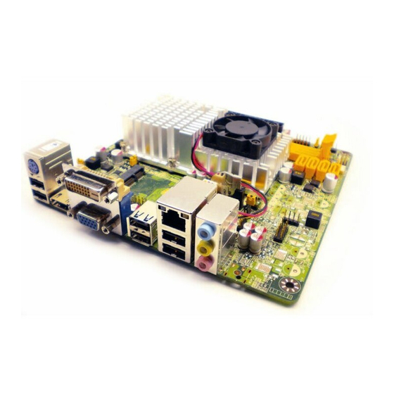
Page 9: Layout Diagram
Layout Diagram NC63 Series Rear I/O RJ-45 LAN Connector PS/2 Line-In Keyboard Line-Out Connectors HDMI MIC-IN Connector Connector Connectors NC63P Series Rear I/O RJ-45 LAN Connector PS/2 Line-In Keyboard Line-Out DC12V Connectors HDMI MIC-IN Connector Connector Connectors... - Page 10 Serial Port Header ATOM CPU HDMI Port DDRII Slot x2 Mini-PCIE Slot GPIO Header DVI over VGA port ATX Power LPC Header Connector NVIDIA MCP7A-ION 8M DIP BIOS SYS FAN2 USB Port RJ-45 over USB Port JBAT USB Headers Audio CDIN Header...
- Page 11 Over USB Port Serial Port Header ATOM CPU HDMI Port DDRII Slot x2 Mini-PCIE Slot GPIO Header DVI over VGA port LPC Header NVIDIA MCP7A-ION 8M DIP BIOS SYS FAN2 USB Port SATA DISK Power Connector RJ-45 over USB Port...
- Page 12 Jumper Jumper Name Description JBAT CMOS RAM Clear Function Setting 3-pin Block KB/MS Power on Function Setting 3-pin Block JP3/JP5 USB Power on Function Setting 3-pin Block Connectors Connector Name Description DC12V_IN (for NC63P ) DC power Connector DC Jack SATA_PWR(for NC63P) Power out Connector 4-pin Connector...
-
Page 13: Jumper Setting
CIR Header 4-pin Block GPIO_CON GPIO header 10-pin Block LPC_CON LPC Header 12-pin Block Chapter 2 Hardware Installation 2-1 Jumper Setting (1) Clear CMOS (3-pin): JBAT JBAT JBAT 2-3 closed Clear CMOS 1-2 closed Normal CMOS RAM Clear Setting (2) JP1: KB/MS Power on Function Enabled/Disabled (3-pin) 1-2 Closed KB/MS Power ON Disable (Default) 2-3 Closed... - Page 14 (3) USB Power on Function Enabled/Disabled: JP3 1-2 Closed USB Power On Disable (Default) 2-3 Closed USB Power ON Enabled JP3:USB Power On Setting (4) USB Power on Function Enabled/Disabled: JP5 2-3 closed USB Power On 2 closed USB Power On Disable Enabled efault) JP5:USB Power-On Setting...
-
Page 15: Connectors And Headers
Connectors and Headers 2-2-1 Connectors (1) Rear Panel Connectors RJ-45 LAN Connector PS/2 Line-In Keyboard Line-Out DC12V -for NC63P Connectors series only HDMI MIC-IN Connector Connector Connectors (2) Serial-ATA Port connector: SATA1/SATA2/SATA3/SATA4 SATA1 SATA2 SATA3 SATA4 Serial-ATAII Connector... -
Page 16: Headers
2-2-2 Headers (1) Front panel audio (9-pin): FP_AUDIO AUDIO Pin 1 Line-O ut, M IC H ead ers (2) CD AUDIO-In Headers (4-pin): CDIN CD-R CD-L CDIN CD Audio-In Headers... - Page 17 (3) USB Port Headers (9-pin): USB1/USB2 Pin 1 USB Port Header Front Panel Header: JW-FP PWRLED Pin 1 SPEAK Pin 1 JW FP Pin 1 System Case Connections...
- Page 18 (5)FAN Speed Headers (3-pin): CPUFAN, SYSFAN1/SYSFAN2 Pin1: GND Pin2: +12V fan power Pin3: Fan clock CPUFAN SYSFAN2 SYSFAN1 (6) COM Port Header: COM1 Pin 1 COM Connector...
- Page 19 (7) CIR Header: CIR CIR Header GPIO Header (9-pin): GPIO_CON GPIO Pin 1 GPIO Connector...
- Page 20 LPC Connector (12-pin): LPC_CON Pin 1 LPC Connector...
-
Page 21: Chapter 3 Introducing Bios
Chapter 3 Introducing BIOS Notice! The BIOS options in this manual are for reference only. Different configurations may lead to difference in BIOS screen and BIOS screens in manuals are usually the first BIOS version when the board is released and may be different from your purchased motherboard. -
Page 22: Enterning Setup
• Press <+>/<–> keys when you want to modify the BIOS parameters for the active option. Entering Setup Power on the computer and by pressing <Del> immediately allows you to enter Setup. If the message disappears before your respond and you still wish to enter Setup, restart the system to try again by turning it OFF then ON or pressing the “RESET”... - Page 23 Figure 3-1 Standard BIOS Features Use this Menu for basic system configurations. Advanced BIOS Features Use this menu to set the Advanced Features available on your system. Advanced Chipset Features Use this menu to change the values in the chipset registers and optimize your system’s performance.
-
Page 24: Standard Bios Features
PC Health Status Use this item to configure hardware health status. Thermal Throttling Options Use this item to configure CPU thermal throttling options. Power User Overclock Settings Use this item to change power user overcook settings. Password Settings Use this item to set BIOS supervisor password and user password. Load Optimal Defaults Use this menu to load the BIOS default values these are setting for optimal performances system operations for performance use. - Page 25 System Date The date format is <day><month><date><year>. Day of the week, from Sun to Sat, determined by BIOS. Read-only. Month The month from Jan. through Dec. Date The date from 1 to 31 can be keyed by numeric function keys. The year depends on the year of the BIOS.
-
Page 26: Advanced Bios Features
S.M.A.R.T.: This option allows you to enable the HDD S.M.A.R.T Capability (Self-Monitoring, Analysis and Reporting Technology). The optional settings are Auto; Disabled; and Enabled. 32 Bit Data Transfer: the optional settings are: Disabled and Enabled. System Memory This item will show information about the memory modules(s) installed. 3-5 Advanced BIOS Features Boot Sector Virus Protection The selection Allow you to choose the VIRUS Warning feature for IDE Hard Disk boot sector... - Page 27 Enabled Activates automatically when the system boots up causing a warning message to appear when anything attempts to access the boot sector of hard disk partition table. Quick Boot Allows BIOS to skip certain tests while booting. This will decrease the needed to boot the system.
-
Page 28: Cpu Features
3-5-1 CPU Features Max CPUID Value Limit Set it as Disabled for Windows XP. The optional settings are: Enabled; Disabled. Execute-Disable Bit Capabili When disabled, force the XD feature flag to always return 0. The optional settings are: Enabled; Disabled. Hyper Threading Technology Enabled for Windows XP and Linux(OS optimized for Hyper Threading Technology) and disabled for other OS(OS not optimized for Hyper-Threading Technology). -
Page 29: Advanced Chipset Features
Advanced Chipset Features The Advanced Chipset Features Setup option is used to change the values of the chipset registers. These registers control most of the system options in the computer. Memory Configuration Press Enter to set memory timing by auto or manual mode. The optional settings are: Auto; Manual. -
Page 30: Integrated Pheriphrals
3-7 Integrated Peripherals... -
Page 31: Onboard Satafunction
3-7-1 Onboard SATA Function SATA Mode Select Use this item to set SATA mode. The optional settings are: SATA Mode; RAID Mode; AHCI Mode. IDE Detect Time Out(Sec) Use this item to select the time out value for detecting ATA/ATAPI devices. -
Page 32: Onboard Device Function
3-7-2 Onboard Device Function Onboard Audio Device The optional settings are: Disabled; AZALIA+HD AUDIO; AZALIA ONLY; HD AUDIO ONLY. USB 1.1/2.0 Support Use this item to enable or disable USB 1.1 function support. USB 2.0 Mode The optional settings are: FullSpeed(480Mbps); HiSpeed(12Mbps). USB Keyboard Legacy Support Enable Legacy support for USB keyboard device. -
Page 33: Onboard Superio Function
3-7-3 Onboard Super IO Function Onboard CIR Port Use this item to enable or disable support for onboard CIR port. Serial Port1 Address This allows BIOS to select serial port1 base addresses. 3-8 Power Management Setup The Power Management Setup allows you to configure your system to most effectively save energy saving while operating in a manner consistent with your own style of computer use. - Page 34 Suspend Mode Use this item to select the ACPI sate used for system suspend. The optional settings are: S1(POS); S3(STR). PWR Status after PWR failure The optional settings are: Always Off; Always On; Former Status. Power Button Mode This item determines system to go into On/Off, or suspend when power button is pressed. The optional settings are: On/Off;...
-
Page 35: Miscellaneous Control
3-9 Miscellaneous Control iGPU Spread Spectrum The optional settings are; Disabled; 1.00% Tri-Down; 2.00% Tri-Down; 3.00% Tri -own; 5.00% Tri-Down ; 2.00% Tri-Down(0608). IRQ Resources Set it as Available or Reserved. Available: Specified IRQ is available to be used by PCI/PnP devices. Reserved: Specified IRQ is reserved for used by legacy ISA devices. -
Page 36: Pc Health Status
3-10 PC Health Status This section shows the Status of you CPU, Fan, and Warning for overall system status. This is only available if there is Hardware Monitor onboard. CPU Temperature/ System Temperature/CPUFAN Speed/SYSFAN1 Speed/SYSFAN2 Speed /Vcore/VCC1.0V/+12V/DRAM Voltage/3VCC/ VSB/VBAT This will show the CPU/ /System voltage chart and FAN Speed, etc. -
Page 37: Smart Fan Configuration
3-10-1 Smart FAN Configuration CPUFAN/SYSFAN1/SYSFAN2 Smart Mode The optional settings are: Enabled; Disabled. When set as Enabled, user can set value for CPUFAN/SYSFAN1/SYSFAN2 Full Speed Temp. And CPUFAN/SYSFAN1/SYSFAN2 Idle Temp. CPUFAN/SYSFAN1/SYSFAN2 Full Speed Temp. The setting ranges from 20 to 70. CPUFAN/SYSFAN1/SYSFAN2 Idle Temp. -
Page 38: Thermal Throttling Options
3-11 Thermal Throttling Options CPU Thermal Throttling Options The optional settings are: Enabled; Disabled. When set as Enabled, user can set values for sub-items such as: CPU Thermal Throttling Temp., CPU Thermal Throttling Beep and CPU Thermal Throttling Duty. CPU Thermal Throttling Temp. The setting ranges from 20 to 70. -
Page 39: Power User Overclock Setting
3-12 Power User Overclock Settings System Clock Mode The optional settings are: Auto; Manual.When set as Manual, user can sets FSB frequency depend on CPU ranged from 533 to 800 (MHz) and sets memory frequency from 667 to 1066(MHz). CPU PLL Select The setting ranges from 1.527v(Default) to 2.530v. -
Page 40: Password Setting
The setting ranges from 1.818v(Default) to 2.500v. 3-13 Password Setting You can set either supervisor or user password, or both of them. The differences are: Change Supervisor password: Can enter and change the options of the setup menus. Change User password: Can only enter but do not have the right to change the options of the setup menus. -
Page 41: Save Changes And Exit/Discard Changes And Exit
Load Standard Defaults When you press <Enter> on this item, you get a confirmation dialog box with a message similar to: Pressing <OK> loads the default values that are factory settings for stable performance system operations. 3-15 Save Changes and Exit / Discard Changes and Exit Save Changes and Exit When you press <Enter>...