Advertisement
Instructions - Parts List
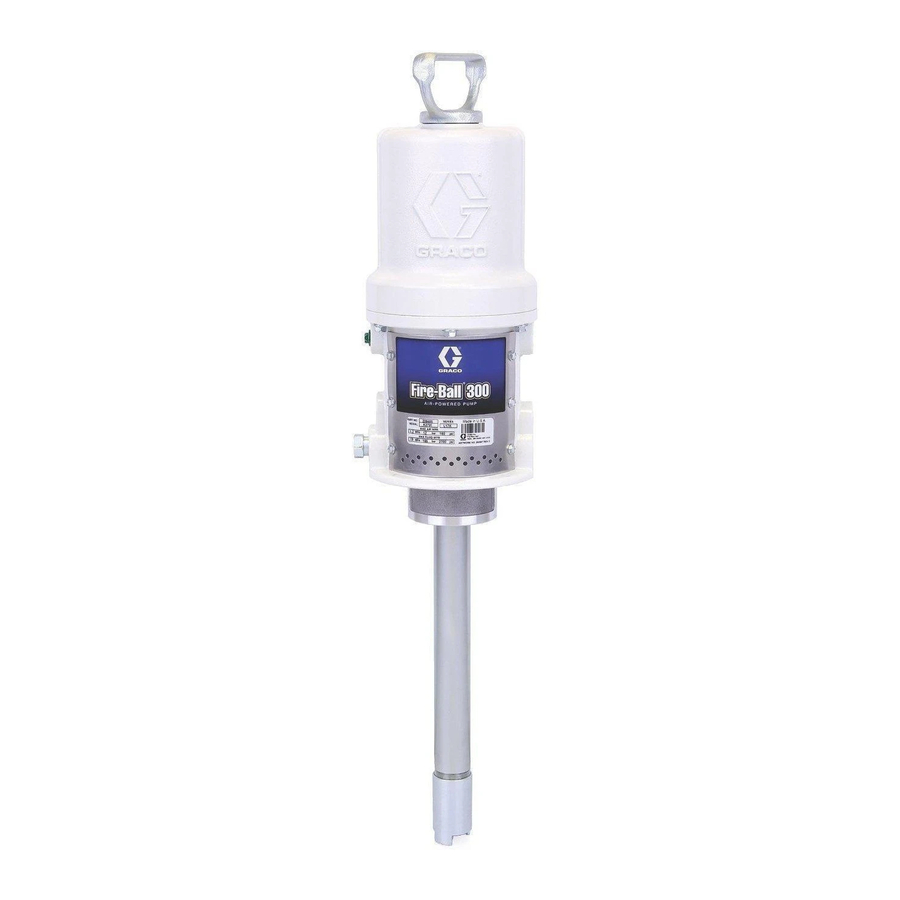
15:1 Fire-Ball
For pumping petroleum-based undercoating material.
2700 psi (18.6 MPa, 186 bar) Maximum Working Pressure
180 psi (1.2 Ma, 12 bar) Maximum Air Input Pressure
Model No. 206405, Series K
35 lb. pail size
Model No. 206699, Series J
120 lb. drum size
Model No. 206700, Series J
400 lb. drum size
Important Safety instructions
Read all warnings and instructions in this manual.
Save these instructions.
WARNING
This product is designed to be used for pumping
non-corrosive and non-abrasive fluids only. Any
other use can cause unsafe operating conditions
and result in component rupture, fire, or explosion,
which can cause serious injury, including skin
injection.
Table of Contents
. . . . . . . . . . . . . . . . . . . . . . . . . . . . . . . .
. . . . . . . . . . . . . . . . . . . . . . . . . . . . . . .
. . . . . . . . . . . . . . . . . . . . . . . . . . . . . . .
. . . . . . . . . . . . . . . . . . . . . . . . . . . .
. . . . . . . . . . . . . . . . . . . . . . . .
. . . . . . . . . . . . . . . . . . . . . . . . . . . . . . . . . .
. . . . . . . . . . . . . . . . . . . .
Dimensional Drawings
. . . . . . . . . . . . . . . . . . . . . . . . . .
. . . . . . . . . . . . . . . . . . . . . . . . .
R
10
. . . . . . . . . . . . . . . . . . .
12
13
. . . . . . . . . . . . . .
16
18
23
. . . . . . . . . . . . . . . . . . .
23
23
24
. . . . . . . . . . . . . . . . . . .
24
300 Pumps
2
6
8
306531AD
04208B
Advertisement
Table of Contents

Related Manuals for Graco 206405


Summary of Contents for Graco 206405
-
Page 1: Table Of Contents
For pumping petroleum–based undercoating material. 2700 psi (18.6 MPa, 186 bar) Maximum Working Pressure 180 psi (1.2 Ma, 12 bar) Maximum Air Input Pressure Model No. 206405, Series K 35 lb. pail size Model No. 206699, Series J 120 lb. drum size Model No. -
Page 2: Warnings
Caution Symbol CAUTION This symbol alerts you to the possibility of damage to or destruction of equipment if you do not follow the instructions. EQUIPMENT MISUSE HAZARD Equipment misuse can cause the equipment to rupture or malfunction and result in serious injury. INSTRUCTIONS D This equipment is for professional use only. - Page 3 SKIN INJECTION HAZARD Spray from the gun, leaks or ruptured components can inject fluid into your body and cause extremely serious injury, including the need for amputation. Fluid splashed in the eyes or on the skin can also cause serious injury. D Fluid injected into the skin might look like just a cut, but it is a serious injury.
- Page 4 FIRE AND EXPLOSION HAZARD Improper grounding, poor ventilation, open flames or sparks can cause a hazardous condition and result in a fire or explosion and serious injury. D Ground the equipment and the object being sprayed. Refer to Grounding on page 7. D If there is any static sparking or you feel an electric shock while using this equipment, stop spray- ing immediately.
- Page 5 Notes 306531 5...
-
Page 6: Installation
Electrically Conductive Air Hose Female Quick Disconnect Coupler Male Quick Disconnect Fitting Air Line Filter Air Regulator and Gauge Bleed-Type Master Air Valve G Air Line Lubricator Pump Runaway Valve Pump Air Inlet Ground Wire Pressure Drain Valve M Electrically Conductive Fluid Hose Spray Gun Fig. - Page 7 CAUTION Provide a bracket for mounting the air accessories. The fittings are not strong enough to support the accessories and may cause one or more to break. NOTE: Install the accessories in the order shown in Figure 1. D A pump runaway valve (H) shuts off the air to the pump if the pump accelerates beyond the pre-ad- justed setting.
-
Page 8: Operation
Pressure Relief Procedure WARNING SKIN INJECTION HAZARD The system pressure must be manually relieved to prevent the system from starting or spraying accidentally. Fluid under high pressure can be injected through the skin and cause serious injury. To reduce the risk of an injury from injection, splashing fluid, or moving parts, follow the Pressure Relief Procedure whenever you:... - Page 9 Notes 306531 9...
-
Page 10: Maintenance
Shutdown and General Care WARNING To reduce the risk of serious injury whenever you are instructed to relieve pressure, always follow the Pressure Relief Procedure on page 8. D Always relieve the pressure when you shut down the pump. D If you are pumping fluid that dries or sets up, flush with a compatible solvent as often as necessary to prevent buildup in the pump and hoses. - Page 11 Packing Nut Adjustment WARNING To reduce the risk of serious injury whenever you are instructed to relieve pressure, always follow the Pressure Relief Procedure on page 8. WARNING Keep your hand and fingers away from the piston when it is moving. As the piston moves into the pump base it can amputate fingers or break tools caught between the moving parts.
-
Page 12: Troubleshooting Guide
WARNING To reduce the risk of serious injury whenever you are instructed to relieve pressure, always follow the Pressure Relief Procedure on page 8. Relieve the Pressure before you check or service any system equipment. Problem Pump fails to operate Continuous air exhaust Erratic pump operation Pump operates, but output is low... -
Page 13: Air Motor Service
Air Motor Service Before you start: D Have all necessary parts on hand. Always replace the glands and bearing when replacing the pack- ings. Use all the parts in the repair kits for the best results. See page 18 to order the kits. D Air Motor Repair Kit 206728. - Page 14 † † † To remove toggles: push in, swing up, ease out. Push toggles (M) in and then up (shown in down position). Turn wires up. Fig. 7 10. Remove the lockwires (34 ) from the adjusting † nuts (33 ) of the transfer valves.
- Page 15 6. Install the bottom adjusting nuts (33) on the poppet valve stems (45 ) and screw the stems into the † grommets (32 ). Screw the top nuts (33 † stems. Before installing the lockwires (34 adjusting nuts, use the gauge 171818 to adjust the transfer valve so there is 0.145 in.
-
Page 16: Displacement Pump Service
Displacement Pump Service Before you start: 1. Have all necessary parts on hand. Whenever you replace the packings, also replace the glands and bearing. If you are using a repair kit, use all the parts for the best results. See the parts pages to order the kits. - Page 17 Displacement Pump Service NOTE: If the pressure-fit brass bearing (15*) needs to be replaced, clamp it in a vise and drive the piston body (13) out with a plastic hammer. The new bearing must be started onto the piston body squarely. 8.
-
Page 18: Parts
Model 206405, Series K 35 lb. pail size † 18 306531 Parts † † † † † † † † 04213B... - Page 19 Model 206405, Series K 35 lb. pail size Part No. Description 100114 BALL, steel, 0.44” (11.2 mm) dia. 1 100400 BALL, steel, 0.75” (19 mm) dia. 101579 PIN, roll, 0.12” (3.2 mm) dia., 0.75” (19 mm) long 150451 GASKET, copper...
- Page 20 Model 206699, Series J 120 lb. drum size Model 206700, Series J 400 lb. drum size † 20 306531 Parts † † † † † † † † 04214B...
- Page 21 Model 206699, Series J 120 lb. drum size Ref. Part No. Description 100114 BALL, steel, 0.44” (11.2 mm) dia. 1 100400 BALL, steel, 0.75” (19 mm) dia. 101579 PIN, roll, 0.12” (3.2 mm) dia., 0.75” (19 mm) long 150451 GASKET, copper 150694 GASKET, copper †...
- Page 22 Notes 22 306531...
-
Page 23: Mounting Hole Layout
Dimensions 3/8 npt(f) Air Inlet 1/4 npt(f) Fluid Outlet Model 206405 13 inches (330 mm) Model 206699 26.69 inches (677.7 mm) Model 206700 33.62 inches (854 mm) 04217B Mounting Hole Layout 2 Hole Mounting Pattern Technical Data Maximum Working Pressure Fluid pressure ratio . -
Page 24: Graco Warranty
Graco Standard Warranty Graco warrants all equipment manufactured by Graco and bearing its name to be free from defects in material and workmanship on the date of sale to the original purchaser for use. With the exception of any special, extended, or limited warranty published by Graco, Graco will, for a period of twelve months from the date of sale, repair or replace any part of the equipment determined by Graco to be defective.