Table of Contents
Advertisement
Quick Links
Instructions - Parts List
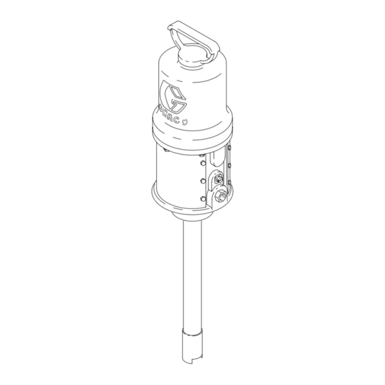
15:1 Fire-Ball
For pumping petroleum-based undercoating material.
2700 psi (18.6 MPa, 186 bar) Maximum Working Pressure
180 psi (1.2 Ma, 12 bar) Maximum Air Input Pressure
Model No. 206405, Series J
35 lb. pail size
Model No. 206699, Series H
120 lb. drum size
Model No. 206700, Series H
400 lb. drum size
Important Safety instructions
Read all warnings and instructions in this manual.
Save these instructions.
WARNING
This product is designed to be used for pumping
non-corrosive and non-abrasive fluids only. Any
other use can cause unsafe operating conditions
and result in component rupture, fire, or explosion,
which can cause serious injury, including skin
injection.
Table of Contents
. . . . . . . . . . . . . . . . . . . . . . . . . . . . . . . .
. . . . . . . . . . . . . . . . . . . . . . . . . . . . . . .
. . . . . . . . . . . . . . . . . . . . . . . . . . . . . . .
. . . . . . . . . . . . . . . . . . . . . . . . . . . .
. . . . . . . . . . . . . . . . . . . . . . . .
. . . . . . . . . . . . . . . . . . . . . . . . . . . . . . . . . .
. . . . . . . . . . . . . . . . . . . .
Dimensional Drawings
. . . . . . . . . . . . . . . . . . . . . . . . . .
. . . . . . . . . . . . . . . . . . . . . . . . .
Copyright 1996, Graco Inc. is registered to I.S. EN ISO 9001
R
10
. . . . . . . . . . . . . . . . . . .
12
13
. . . . . . . . . . . . . .
16
18
23
. . . . . . . . . . . . . . . . . . .
23
23
24
. . . . . . . . . . . . . . . . . . .
24
300 Pumps
2
6
8
306531 rev.AC
04208B
Advertisement
Table of Contents

Related Manuals for Graco Fire-Ball J Series


Summary of Contents for Graco Fire-Ball J Series
-
Page 1: Table Of Contents
Graco Phone Numbers ....GRACO INC. P.O. BOX 1441 MINNEAPOLIS, MN 55440-1441 Copyright 1996, Graco Inc. is registered to I.S. EN ISO 9001... -
Page 2: Warnings
D Read all instruction manuals, tags, and labels before operating the equipment. D Use the equipment only for its intended purpose. If you are not sure, call your Graco distributor. D Do not alter or modify this equipment. Use only genuine Graco parts and accessories. - Page 3 WARNING SKIN INJECTION HAZARD Spray from the gun, leaks or ruptured components can inject fluid into your body and cause extremely serious injury, including the need for amputation. Fluid splashed in the eyes or on the skin can also cause serious injury. D Fluid injected into the skin might look like just a cut, but it is a serious injury.
- Page 4 WARNING FIRE AND EXPLOSION HAZARD Improper grounding, poor ventilation, open flames or sparks can cause a hazardous condition and result in a fire or explosion and serious injury. D Ground the equipment and the object being sprayed. Refer to Grounding on page 7. D If there is any static sparking or you feel an electric shock while using this equipment, stop spray- ing immediately.
- Page 5 Notes 306531 5...
-
Page 6: Installation
To reduce the risk of serious injury including skin optional and required accessories. For help in design- injection, splashing in the eyes or on the skin, and ing a system to suit your needs, contact your Graco injury from moving parts, if you are adjusting or distributor. - Page 7 Installation D Pump: use a ground wire and clamp as shown CAUTION below. Provide a bracket for mounting the air accessories. D Truck bed or platform: according to your local code. The fittings are not strong enough to support the D Fluid hoses: use only electrically conductive hoses.
-
Page 8: Operation
Operation Pressure Relief Procedure WARNING WARNING Never operate the pump with the warning plate (20) or the identification plate (40) removed. These SKIN INJECTION HAZARD plates protect your fingers from pinching or am- The system pressure must be manually putation by moving parts in the air motor. relieved to prevent the system from starting or spraying accidentally. - Page 9 Notes 306531 9...
-
Page 10: Maintenance
Maintenance Shutdown and General Care Flushing WARNING WARNING To reduce the risk of serious injury whenever you To reduce the risk of serious injury whenever you are instructed to relieve pressure, always follow the are instructed to relieve pressure, always follow the Pressure Relief Procedure on page 8. - Page 11 Maintenance Packing Nut Adjustment WARNING To reduce the risk of serious injury whenever you are instructed to relieve pressure, always follow the Pressure Relief Procedure on page 8. PISTON WARNING Keep your hand and fingers away from the piston PINCH POINT when it is moving.
-
Page 12: Troubleshooting Guide
Troubleshooting WARNING WARNING To reduce the risk of serious injury whenever you Never operate the pump with the warning plate are instructed to relieve pressure, always follow the (20) or the identification plate (40) removed. These Pressure Relief Procedure on page 8. plates protect your fingers from pinching or ampu- tation by moving parts in the air motor. -
Page 13: Air Motor Service
Air Motor Service Before you start: CAUTION D Have all necessary parts on hand. Always replace To avoid damaging the cylinder wall, lift the the glands and bearing when replacing the pack- cylinder (51) straight up off the piston (59). Never tilt the ings. - Page 14 Air Motor Service † † † † † † † † † † 0.145” (3.7 mm) † † † † Cutaway View To remove toggles: push in, swing up, ease out. Push toggles (M) in and then up (shown in down position). Cut off tops of poppets as indicated by dotted lines.
- Page 15 Air Motor Service 6. Install the bottom adjusting nuts (33) on the poppet 9. Manually push on the piston rod (41) to move the valve stems (45 ) and screw the stems into the piston (59) up as far as it will go. Grip the trip rod †...
-
Page 16: Displacement Pump Service
Displacement Pump Service Before you start: 1. Have all necessary parts on hand. Whenever you replace the packings, also replace the glands and bearing. If you are using a repair kit, use all the parts for the best results. See the parts pages to order the kits. - Page 17 Displacement Pump Service NOTE: If the pressure-fit brass bearing (15*) needs to 10. Install the gasket (7*[). Screw the riser tube (12) be replaced, clamp it in a vise and drive the piston into the air motor base (55). body (13) out with a plastic hammer. The new bearing 11.
-
Page 18: Parts
Parts Model 206405, Series J 35 lb. pail size † † † † † † † † † 04213B 18 306531... - Page 19 Parts Model 206405, Series J 35 lb. pail size Part No. Description Qty. Part No. Description Qty. 100114 BALL, steel, 0.44” (11.2 mm) dia. 1 160623 . ARM, toggle 100400 BALL, steel, 0.75” (19 mm) dia. 160624 . O-RING, nitrile rubber 101579 PIN, roll, 0.12”...
- Page 20 Parts Model 206699, Series H 120 lb. drum size † Model 206700, Series H 400 lb. drum size † † † † † † † † 04214B 20 306531...
- Page 21 Parts Model 206699, Series H Model 206700, Series G 120 lb. drum size 400 lb. drum size Ref. Ref. Part No. Description Qty. Part No. Description Qty. 100114 BALL, steel, 0.44” (11.2 mm) dia. 1 160261 . NUT, adjusting † 100400 BALL, steel, 0.75”...
- Page 22 Notes 22 306531...
-
Page 23: Mounting Hole Layout
Dimensions Technical Data Maximum Working Pressure ..2700 psi (186 bar) Fluid pressure ratio ......15:1 Air operating range . -
Page 24: Graco Warranty
With the exception of any special, extended, or limited warranty published by Graco, Graco will, for a period of twelve months from the date of sale, repair or replace any part of the equipment determined by Graco to be defective.