Intel S5500WB Technical Product Specification
A dual socket server
Hide thumbs
Also See for S5500WB:
- Spares/parts list and configuration manual (9 pages) ,
- Spares/parts list and configuration manual (8 pages) ,
- Specification (117 pages)

Related Manuals for Intel S5500WB


Summary of Contents for Intel S5500WB
- Page 1 Intel Server Board S5500WB ® Technical Product Specification Intel order number E53971-004 Revision 1.3 August 2009 Enterprise Platforms and Services Division...
- Page 2 Revision History Intel® Server Board S5500WB TPS Revision History Date Revision Modifications Number 03/30/2009 Initial Release 04/29/2009 Formatting corrections 05/20/2009 Updated heatsink installation steps Corrected processor fault table Added jumper location figure 08/03/2009 Updated memory support Corrected PCIe slot speed Removed S4 support Revision 1.3...
- Page 3 Intel disclaims any express or implied warranty, relating to sale and/or use of Intel products including liability or warranties relating to fitness for a particular purpose, merchantability, or infringement of any patent, copyright or other intellectual property right.
-
Page 4: Table Of Contents
Section Outline ......................1 Server Board Use Disclaimer .................. 1 2. Server Board Overview ......................2 ® Intel Server Board S5500WB Server Board............4 Server Board Connector and Component Layout............ 6 2.2.1 Board Rear Connector Placement................8 2.2.2 Server Board Mechanical Drawings ................ 8 3. - Page 5 Intel® Server Board S5500WB TPS Table of Contents 3.7.1 Serial ATA Support ....................29 3.7.2 USB 2.0 Support....................29 Network Interface Controller (NIC) ................ 30 3.8.1 MAC Address Definition..................30 3.8.2 LAN Connector Ordering ..................31 Integrated Baseboard Management Controller............31 3.9.1...
- Page 6 Table of Contents Intel® Server Board S5500WB TPS 5.5.1 Wake On LAN (WOL) .................... 42 5.5.2 PCI Express* Power management ................ 43 5.5.3 PMBus*........................43 SMBUS Architecture Block ..................43 5.6.1 SMBUS Device Addresses ..................43 6. Configuration Jumpers...................... 45 6.1.1...
- Page 7 Intel® Server Board S5500WB TPS Table of Contents 7.4.6 Serial Port Connectors................... 65 7.4.7 USB Connectors ....................65 Fan Headers ......................66 8. Intel Light-Guided Diagnostics..................67 5-V Standby LED ....................67 Fan Fault LEDs...................... 68 System Status LED....................68 DIMM Fault LEDs ....................
- Page 8 Table of Contents Intel® Server Board S5500WB TPS 11.3.2 ICES-003 (Canada) ....................86 11.3.3 Europe (CE Declaration of Conformity) ..............87 11.3.4 BSMI (Taiwan) ....................... 87 11.3.5 KCC (Korea) ......................87 Appendix A: POST Code LED Decoder................... 88 Appendix B: Video POST Code Errors..................95 Glossary.............................
- Page 9 Figure 2. Intel Server Board S5500WB SSI.................. 5 ® Figure 3. Intel Server Board S5500WB Components (both SKUs are shown) ......6 Figure 4. Rear Panel Connector Placement: ................8 Figure 5. Baseboard and Mounting holes ..................9 Figure 6. Connector Locations....................10 Figure 7.
- Page 10 List of Figures Intel® Server Board S5500WB TPS Figure 32. Power Distribution Diagram ..................82 Figure 33. Diagnostic LED Placement Diagram ................ 88 Revision 1.3 Intel order number E53971-004...
- Page 11 Intel® Server Board S5500WB TPS List of Tables List of Tables ® Table 1. Intel Server Board S5500WB Feature Set ..............2 ® Table 2. Intel Server Board S5500WB System Interconnects............ 7 ® Table 3. Intel Server Board S5500WB Features ............... 13 Table 4.
- Page 12 List of Tables Intel® Server Board S5500WB TPS Table 30. IPMB Header 4-pin (J1B2)..................54 Table 31. SGPIO Header (J1B1) ....................54 Table 32. Front Panel SSI Standard 24-pin Connector Pin-out (J1E1) ........54 Table 33. Power LED Indicator States..................56 Table 34.
- Page 13 Intel® Server Board S5500WB TPS List of Tables <This page intentionally left blank.> Revision 1.3 xiii Intel order number E53971-004...
-
Page 15: Introduction
Intel ensures through its own chassis development and testing that when Intel server building blocks are used together, the fully integrated system will meet the intended thermal requirements of these components. It is the... -
Page 16: Server Board Overview
Intel® Server Board S5500WB TPS Server Board Overview ® The Intel Server Board S5500WB is a monolithic printed circuit board (PCB) with features designed to support the Internet Portal Data Center markets. The following table provides a high-level product feature list. ®... - Page 17 Intel® Server Board S5500WB TPS Server Board Overview Feature Description Power Connections SSI SKU One SSI-EEB compliant 24-pin main power connector (SSI only SKU) One SSI compliant 8-pin CPU power connector One SSI compliant 5-pin power control Connector (SSI only SKU)
-
Page 18: Intel ® Server Board S5500Wb Server Board
Intel ® Server Board S5500WB Server Board ® The Intel Server Board S5500WB has two board SKUs. An SSI-compliant and a 12-V only SKU. The board layouts of the SKUs are shown. ® Figure 1. Intel Server Board S5500WB 12V Revision 1.3... -
Page 19: Figure 2. Intel Server Board S5500Wb Ssi
Intel® Server Board S5500WB TPS Server Board Overview Figure 2. Intel Server Board S5500WB SSI Revision 1.3 Intel order number E53971-004... -
Page 20: Server Board Connector And Component Layout
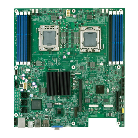
Server Board Overview Intel® Server Board S5500WB TPS Server Board Connector and Component Layout AF003051 ® Figure 3. Intel Server Board S5500WB Components (both SKUs are shown) Revision 1.3 Intel order number E53971-004... -
Page 21: Table 2. Intel ® Server Board S5500Wb System Interconnects
Intel® Server Board S5500WB TPS Server Board Overview ® Table 2. Intel Server Board S5500WB System Interconnects Description Description ® Dual Intel I/O Expansion Module Processor Socket 1 Connectors PCI Express x16 Gen2 8 Pin CPU Connector Remote Management Module 3... -
Page 22: Board Rear Connector Placement
Server Board Overview Intel® Server Board S5500WB TPS 2.2.1 Board Rear Connector Placement ® The Intel Server Board S5500WB has the following board rear connector placement: AF003052 Figure 4. Rear Panel Connector Placement: Description Description ID LED RJ-45 GbE LAN connector... -
Page 23: Figure 5. Baseboard And Mounting Holes
Intel® Server Board S5500WB TPS Server Board Overview Baseboard and Mounting holes Figure 5. Revision 1.3 Intel order number E53971-004... -
Page 24: Figure 6. Connector Locations
Server Board Overview Intel® Server Board S5500WB TPS Figure 6. Connector Locations Revision 1.3 Intel order number E53971-004... -
Page 25: Figure 7. Primary Side Height Restrictions
Intel® Server Board S5500WB TPS Server Board Overview Figure 7. Primary Side Height Restrictions Revision 1.3 Intel order number E53971-004... -
Page 26: Figure 8. Secondary Side Height Restrictions
Server Board Overview Intel® Server Board S5500WB TPS Figure 8. Secondary Side Height Restrictions Revision 1.3 Intel order number E53971-004... -
Page 27: Functional Architecture
® The Intel Server Board S5500WB is a purpose build, power-optimized server used in a 1U rack. Memory and processor socket placement is made to minimize the amount of fan power required to cool these components. Voltage Regulators (VRDs) are optimized for a particular range of memory and CPU power that suits the target Internet Portal Datacenter (IPDC) segment of the market. -
Page 28: Functional Block Diagram
Front Panel Rear Serial USB x2 x2 USB Port Rear Panel USB x2 x2 Optical Internal Drive Serial RMII Header FLASH DRAM RMM3 FLASH AF003058 ® Figure 9. Intel Server Board S5500WB Functional Block Diagram Revision 1.3 Intel order number E53971-004... -
Page 29: Intel ® Xeon ® 5500 Series
5500 series processor is a series of multi-core processors based on the 45 nm ® process technology. Processor features vary by SKU and include up to two Intel QPI point-to- point links capable of up to 6.4 GT/s, up to 8 MB of shared cache, and an integrated memory controller. -
Page 30: Table 4. Mixed Processor Configurations
Functional Architecture Intel® Server Board S5500WB TPS • Major: If the Post Error Pause setup option is enabled, the system goes directly to the error manager. Otherwise, the system continues to boot and no prompt is given for the error. The error is logged to the error manager. -
Page 31: Installing Or Replacing The Processor
Alerts the Integrated BMC about the configuration error. • Does not disable the processor. • Displays “0195: Processor 0x Intel(R) QPI speed mismatch” message in the Error Manager. • If POST Error Pause is disabled in the Setup, continues to boot in a degraded state. -
Page 32: Figure 11. Removing The Socket Cover
Functional Architecture Intel® Server Board S5500WB TPS Pin 1 AF003060 Figure 11. Removing the socket cover 7. Remove the protective socket cover. (See letter “D” in Figure 11) 8. Align the pins of the processor with the socket and insert the processor into the socket. -
Page 33: Figure 13. Package Installation/Remove Feature
Intel® Server Board S5500WB TPS Functional Architecture posts to physically prevent mis-orientation of the package. These orientation features also provide an initial rough alignment of the package to the socket. C. The socket has alignment walls at the four corners to provide final alignment of the package. -
Page 34: Qpi)
Functional Architecture Intel® Server Board S5500WB TPS Figure 14. Installing/Removing Heatsink 3.3.3.3 Removing the Processor Heatsink To remove the heatsink, follow these steps: 1. Loosen the four captive screws on the heatsink corners in a diagonal manner according to the numbers shown in Figure 1 as follows: a) Starting with the screw at location 1, loosen it by giving it two rotations in the anticlockwise direction and stop. -
Page 35: Intel ® Quickpath Memory Controller
® ® Intel 5500 Series processor produces up to three channels of DDR3 memory. The Intel Memory Controller supports DDR3 800, DDR3 1066, and DDR3 1333 memory technologies. The memory controller supports both Registered DIMMs (RDIMMs) and Unbuffered DIMMs (UDIMMs). -
Page 36: Memory Subsystem Nomenclature
® The Intel Server Board S5500WB uses a 2:1:1 memory DIMM layout. A 2:1:1 layout was chosen for its lowest power for a particular bandwidth and because it allows the maximum possible bandwidth when a 1:1:1 memory population is used. -
Page 37: Ecc Support
For details, see the relevant operating system manuals. 3.4.6 Memory Population Rules ® You should populate the memory slots of DDR3 channels furthest from the Intel 5500 series processor first. Therefore, if A1 is empty, you cannot populate/use A2. Figure 16. Memory Channel Population Revision 1.3... -
Page 38: Installing And Removing Memory
Functional Architecture Intel® Server Board S5500WB TPS 3.4.7 Installing and Removing Memory The silkscreen on the board next to CPU1 displays: DIMM_A2, DIMM_A1, DIMM_B1, DIMM_C1, and next to CPU2 display: DIMM_D2, DIMM_D1, DIMM_E1, DIMM_F1 starting from the inside of the board. DIMM_A1 is the blue socket closest to the CPU 1 socket. For memory channel A, the server board requires DDR3 DIMMs within a channel to be populated starting with the DIMM farthest from the processor. -
Page 39: Channel-Independent Mode
Channel mirroring is a RAS feature in which two identical images of memory data are ® maintained, thus providing maximum redundancy. On the Intel 5500 series based Intel server boards, mirroring is achieved across channels. Active channels hold the primary image and the Revision 1.3... -
Page 40: Memory Error Led
The Intel 5500 Chipset component is an I/O Hub (IOH). The Intel 5500 Chipset provides a ® connection point between various I/O components and Intel processors using the Intel interface. ® The Intel 5500 Chipset IOH is capable of interfacing with up to 24 PCI Express* lanes, which can be configured in various combinations of x4, x8, x16 and limited x2 and x1 devices. -
Page 41: Ioh24D Pci Express
® Intel 5500 Chipset IOH PCI Express* ® PE9, PE10 40 Gb/S PCI Express* x4 PCI Express* Gen2 throughput to each of the two Intel Gen2 I/O Expansion Module connectors. ® Intel 5500 Chipset IOH PCI Express* 3.5.1.1 Direct Cache Access (DCA) The DCA mechanism is a system-level protocol in a multi-processor system to improve I/O network performance by providing higher system performance. -
Page 42: Management Engine
PECI 2.0 Proxy: SPS offers a means for a BMC without a PECI 2.0 interface to use the ME as a PECI proxy. The BMC on Intel servers already has a PECI 2.0 interface, so this SPS capability is not used. -
Page 43: Serial Ata Support
® implementation and provides the ability to use an Intel Embedded Server RAID Technology II ® volume as a boot disk as well as to detect any faults in the Intel Embedded Server RAID Technology II volume(s). 3.7.2 USB 2.0 Support The USB controller functionality integrated into ICH10R provides the server board with an interface for up to 12 USB 2.0 ports. -
Page 44: Network Interface Controller (Nic)
Green (Left) Blinking Transmit / Receive activity 3.8.1 MAC Address Definition ® The Intel Server Board S5500WB has the following four MAC addresses assigned to it at the Intel factory. • NIC 1 MAC address Revision 1.3 Intel order number E53971-004... -
Page 45: Lan Connector Ordering
NIC 1 MAC address +3 ® The Intel Server Board S5500WB has a white MAC address sticker included with the board. The sticker displays the NIC 1 MAC address in both bar code and alphanumeric formats. 3.8.2 LAN Connector Ordering ®... - Page 46 Functional Architecture Intel® Server Board S5500WB TPS • LPC to SPI Bridge for system BIOS support • SMI and PME support • ACPI compliant • Wake-up control The Pilot II contains an integrated KVMS subsystem and graphics controller with the following features: •...
-
Page 47: Integrated Bmc Embedded Lan Channel
Intel® Server Board S5500WB TPS Functional Architecture Figure 19. Integrated BMC Hardware 3.9.1 Integrated BMC Embedded LAN Channel The Integrated BMC hardware includes two dedicated 10/100 network interfaces. These interfaces are not shared with the host system. At any time, you can enable only one dedicated interface for management traffic. -
Page 48: 3.11 Wake-Up Control
Functional Architecture Intel® Server Board S5500WB TPS 3.11 Wake-up Control Wake from S1 is supported on LAN, USB, Serial port, and PCI Express* slots. 3.12 Integrated Video Support The SVGA subsystem supports a variety of modes, up to 1600 x 1200 resolution in 8 / 16 / 32 bpp modes under 2D. -
Page 49: Front Panel Video
® The Intel Server Board S5500WB provides a mechanism to support video to the front panel via the use of an internal header. When a monitor is plugged into the front panel video connector, the rear panel video stream is disconnected. -
Page 50: Slot 1 Pci Express* X8 Connector
Server Board S5520UR are supported on the Intel Server Board S5500WB. ® ® The Intel I/O Expansion Module is also required to inform the IOH of the Intel I/O Expansion Module Bus usage, PEWIDTH bit 1 is to be used for this. ® Intel I/O Expansion Module Table 12. -
Page 51: Intel® I/O Expansion Modules
Intel® I/O Expansion Modules Intel ® I/O Expansion Modules ® The Intel Server Board S5500WB supports a variety of I/O Module options using 2x4 PCI ® Express* Gen2 Intel I/O Expansion Module connectors on the rear of the server board. Each ® Intel I/O Expansion Module connector is a 50-pin, surface mount, 0.8mm pitch, header. - Page 52 Quad port Gigabit Ethernet I/O Expansion Module based on AXX4GBIOMOD2 ® the Intel 82576EB Gigabit Ethernet Controller. AXXIBQDRMOD InfiniBand* I/O Expansion Module Single Port QDR. ® For more information, refer to the I/O modules in the Intel I/O Expansion Modules Hardware Specification. Revision 1.3 Intel order number E53971-004...
-
Page 53: Platform Management Features
To a large extent, this is background information. BIOS Feature Overview ® The Intel Server Board S5500WB product uses the AMI Aptio v3.x code base. 5.1.1 EFI Support The platform BIOS is compiled to support the 64-bit EFI environment, natively. This allows operating systems that are EFI-aware to take advantage of the EFI-boot process in a native 64- bit environment. -
Page 54: Server Engines Pilot Ii Controller
Super I/O functions, and also provides an ARM 926- EJ microcontroller to host the embedded server management firmware stack. The Server Engines Pilot II baseboard management controller across Intel’s server product line ® with two different management feature set configurations: Basic and Advanced. The Intel Server Board S5500WB supports both. -
Page 55: Bmc Basic Features
® The Intel Server Board S5500WB product includes support for an upgrade module to support the advanced server management functionality. The Remote Management Module 3 supports an 8 MB SPI Flash, which connects to the integrated BMC SPI interface. This is in addition to the local integrated BMC 8 MB SPI flash connected to the PILOT II IBMC down on the board. -
Page 56: Management Engine (Me)
ME on client platforms. Server Platform Services (SPS) are value-added platform management options that enhance the value of Intel platforms and their component ingredients (CPUs, chipsets, and I/O components). Each service is designed to function independently wherever possible, or grouped together with one or more features in flexible combinations to allow OEMs to differentiate platforms. -
Page 57: Pci Express* Power Management
L0 and L3 power management states are supported on all PCI Express* slots and embedded end points. 5.5.3 PMBus* ® Power supplies that have PMBus* 1.1 are supported and required to support Intel Dynamic ® ® Power Node Manager. Intel... - Page 58 Platform Management Features Intel® Server Board S5500WB TPS Main Power Power Device SMBus Note Rail Rail Address DB803 0xDC CPU0 DIMM 1A 0xA0 CPU0 DIMM 2A 0xA2 CPU0 DIMM 1B 0xA4 CPU0 DIMM 1C 0xA6 CPU0 DIMM 1D 0xA8 CPU0 DIMM 2D...
-
Page 59: Configuration Jumpers
The following table provides a summary and description of configuration, test, and debug ® jumpers on the Intel Server Board S5500WB. The server board has several 3-pin jumper blocks that can be used. Pin 1 on each jumper block can be identified by the following symbol on the silkscreen: ▼... -
Page 60: Force Ibmc Update (J1B5)
Configuration Jumpers Intel® Server Board S5500WB TPS Table 16: Server Board Jumpers (J1B5, J1C2, J1C3, J1B4, J6A3, J6A2) Mode of Jumper Name Jumper Position Note Operation J1B5: BMC Force Normal IBMC GPIO[1] is pulled HIGH. Default position. Update jumper Update IBMC GPIO[1] is pulled LOW. -
Page 61: Password Clear (J1C2)
Intel® Server Board S5500WB TPS Configuration Jumpers 4. Close the server chassis. 5. Reconnect the AC cord and power up the server. 6. Perform the BMC firmware update procedure as documented in the README.TXT file included in the given BMC firmware update package. After successful completion of the firmware update process, the firmware update utility may generate an error stating the BMC is still in update mode. -
Page 62: Bios Recovery Mode (J1C3)
® The Intel Server Board S5500WB uses BIOS recovery to repair the system BIOS from flash corruption in the main BIOS and Boot Block. This 3-pin jumper is used to reload the BIOS when the image is suspected to be corrupted. For directions on how to recover the BIOS, refer to the specific BIOS release notes. -
Page 63: Reset Bios Configuration (J1B4)
Intel® Server Board S5500WB TPS Configuration Jumpers 6.1.4 Reset BIOS Configuration (J1B4) This jumper used to be the CMOS Clear jumper. Since the previous generation, the BIOS has moved CMOS data to the NVRAM region of the BIOS flash. The BIOS checks during boot to determine if the data in the NVRAM needs to be set to default. -
Page 64: Me Firmware Force Update (J7A2)
Configuration Jumpers Intel® Server Board S5500WB TPS J6A3, 2-3 jumpered: External video connector is primary, but video can come out of internal video connector if you connect to it. 6.1.6 ME Firmware Force Update (J7A2) Pins ME Firmware Update Mode... -
Page 65: Connector / Header Locations And Pin-Out
Intel® Server Board S5500WB TPS Connector / Header Locations and Pin-out Connector / Header Locations and Pin-out Power Connectors Table 22. SSI SKU 24-pin 2x12 Connector (J9B1) Signal Name Signal Name +3.3V +3.3V +3.3V -12V PS_ON PWR_GD SB5V +12V +12V +3.3V... -
Page 66: Table 26. 12-V Only Power Control (Replaces The 1X5 Power Control) (J9D1)
Connector / Header Locations and Pin-out Intel® Server Board S5500WB TPS Signal Name +12V +12V +12V +12V Table 26. 12-V Only Power Control (replaces the 1x5 power control) (J9D1) (FOXCONN ELECTRONICS INC HF1107V-P1 or TYCO ELECTRONICS CORPORATION 5-104809-6) Signal Name... -
Page 67: System Management Headers
Intel Remote Management Module 3. There is no support for third-party management cards on this server board. ® ® Note: This connector is not compatible with the Intel Remote Management Module (Intel ® ® RMM) or the Intel Remote Management Module 2 (Intel RMM2). -
Page 68: Hard Drive Activity (Input) Led Header
Connector / Header Locations and Pin-out Intel® Server Board S5500WB TPS If this switch is used while the system power is still applied, then the main power rail regulators is disabled first, then the main 3.3V S/B regulator is disabled, removing power from the BMC. -
Page 69: Power Button
Intel® Server Board S5500WB TPS Connector / Header Locations and Pin-out Signal Name Signal Name FP_PWR_BTN_N NIC1_ACT_LED_N GND (Power Button GND) NIC1_LINK_LED_N BMC_RST_BTN_N SMB_SENSOR_3V3STB_DATA GND (Reset GND) SMB_SENSOR_3V3STB_CLK FP_ID_BTN_N FP_CHASSIS_INTRU NIC2_ACT_LED_N FP_NMI_BTN_N NIC2_LINK_LED_N Combined system BIOS and the Integrated BMC support provide the functionality of the various supported control panel buttons and LEDs. -
Page 70: Chassis Identify Button
Connector / Header Locations and Pin-out Intel® Server Board S5500WB TPS to generate an NMI (non-maskable interrupt). The NMI is captured by the BIOS during boot services time and by the operating system during runtime. During boot services time, the BIOS halts the system upon detection of the NMI. -
Page 71: Table 34. System Status Led
Intel® Server Board S5500WB TPS Connector / Header Locations and Pin-out Table 34. System Status LED Color State System Status Description Green Solid on System ready Green ~1 Hz Degraded BIOS detected blink 1. Unable to use all of the installed memory (more than one DIMM installed). -
Page 72: Chassis Id Led
Connector / Header Locations and Pin-out Intel® Server Board S5500WB TPS Color State System Status Description Amber Solid on Fatal Fatal alarm – system has failed or shut down: BIOS Detected 1. DIMM failure when there is one DIMM present and no good memory is present. -
Page 73: I/O Connectors
Connector / Header Locations and Pin-out I/O Connectors 7.4.1 PCI Express* Connectors ® The Intel Server Board S5500WB has two PCI Express slots. The pin-outs for the slots are shown in the following tables. Table 36. Slot 6 Riser Connector (J4B1) Side Side Side... -
Page 74: Table 37. Slot 1 Pci Express* X8 Connector (J1B3)
Connector / Header Locations and Pin-out Intel® Server Board S5500WB TPS Side Side Side Side PCI Express* Signal PCI Express* Signal PCI Express* Signal PCI Express* Signal PETxN4 PERxP14 PERxP4 PERxN14 PERxN4 PETxP15 PETxP5 PETxN15 PETxN5 PERxP15 PERxP5 PRSNT2# PERxN15... -
Page 75: Vga Connectors
Intel® Server Board S5500WB TPS Connector / Header Locations and Pin-out Pin-Side B PCI Express* Spec Signal Description Pin-Side A PCI Express* Spec Description Signal PRSNT2# 8X end 7.4.2 VGA Connectors The following table details the pin-out definition of the external VGA connector (J6A1). -
Page 76: Nic Connectors
Connector / Header Locations and Pin-out Intel® Server Board S5500WB TPS Signal Name Signal Name Vsync Hsync VIDEO_IN_USE signal DDC_SDA DDC_SCL 7.4.3 NIC Connectors The server board provides two stacked RJ-45 / 2xUSB connectors side-by-side on the back edge of the board (J8A2, J9A1). The pin-out for NIC connectors are identical and are defined in the following table. -
Page 77: Sata Connectors
I/O Expansion Modules for use on this server board. For more ® ® information on the supported Intel I/O Expansion Modules, refer to the Intel Server Board IO ® Module Hardware Specification. The following table details the pin-out of the Intel Expansion Module connectors. Revision 1.3 Intel order number E53971-004... -
Page 78: Table 42. 50-Pin Intel ® I/O Expansion Module Connector Pin-Out (J2B1, J3B1)
Connector / Header Locations and Pin-out Intel® Server Board S5500WB TPS ® Table 42. 50-pin Intel I/O Expansion Module Connector Pin-out (J2B1, J3B1) Revision 1.3 Intel order number E53971-004... -
Page 79: Serial Port Connectors
Intel® Server Board S5500WB TPS Connector / Header Locations and Pin-out 7.4.6 Serial Port Connectors The server board provides one external RJ-45 Serial A port (J7A1) and one internal 9-pin serial B header (J1A2). The following tables define the pin-outs. -
Page 80: Fan Headers
Connector / Header Locations and Pin-out Intel® Server Board S5500WB TPS One low-profile 2x5 connectors (J1D4) on the server board provides an option to support low- profile USB based embedded flash devices. The pin-out of the connector is detailed in the following table. -
Page 81: Intel Light-Guided Diagnostics
Intel® Server Board S5500WB TPS Intel® Light-Guided Diagnostics Intel® Light-Guided Diagnostics The server boards have several onboard diagnostic LEDs to assist in troubleshooting board- level issues. This section provides a description the location and function of each LED on the server board. -
Page 82: Fan Fault Leds
Intel® Light-Guided Diagnostics Intel® Server Board S5500WB TPS Fan Fault LEDs Fan fault LEDs are present for the six fans and are located near each CPU fan header. AF003115 Figure 23. Fan Fault LED Locations FLTMEM2R FLTCPU1 FLTMEM2 FLTCPU1A FLTCPU2A... -
Page 83: Figure 24. System Status Led Location
Intel® Server Board S5500WB TPS Intel® Light-Guided Diagnostics System Status LED AF003116 Figure 24. System Status LED Location The bi-color System Status LED operates as follows: Table 50. System Status LED Color State System Status Description Green Solid on System ready Revision 1.3... - Page 84 Intel® Light-Guided Diagnostics Intel® Server Board S5500WB TPS Color State System Status Description System degraded: BIOS detected 1. Unable to use all of the installed memory (more than one DIMM installed). 2. In a mirrored configuration, when memory mirroring takes place and system loses memory redundancy.
- Page 85 Intel® Server Board S5500WB TPS Intel® Light-Guided Diagnostics Color State System Status Description Fatal alarm – system has failed or shut down: BIOS Detected 1. DIMM failure when there is one DIMM present and no good memory is present. 2. Run-time memory uncorrectable error in non- redundant mode.
-
Page 86: Dimm Fault Leds
Intel® Light-Guided Diagnostics Intel® Server Board S5500WB TPS DIMM Fault LEDs Each DIMM slot has a DIMM Fault LED near the DIMM slot. AF003117 Figure 25. DIMM Fault LEDs Locations FLT_F FLT_A2 FLT_E FLT_A1 FLT_D1 FLT_B FLT_D2 FLT_C Revision 1.3... -
Page 87: Post Code Diagnostic Leds
Intel® Server Board S5500WB TPS Intel® Light-Guided Diagnostics POST Code Diagnostic LEDs Eight amber POST code diagnostic LEDs are located on the back edge of the server board in the rear I/O area of the server board by the VGA connector. -
Page 88: Front Panel Support
Front Panel Support ® The Intel Server Board S5500WB supports SSI standard front panel boards. The front panel support is provided by a SSI compatible 2x12-pin signal connector. The front panel connector supports the following diagnostic LEDs. Table 51. Standard Front Panel Functionality... -
Page 89: Design And Environmental Specifications
Intel® Server Board S5500WB TPS Design and Environmental Specifications Design and Environmental Specifications Fan Speed Control Thermal Management Fan speed control supports the following thermal sensors: • Discrete board level digital thermal sensor TMP75 • Front panel Temp Sensor (if present) •... -
Page 90: Figure 28: Location Of Fan Connectors
Design and Environmental Specifications Intel® Server Board S5500WB TPS The following tables show a basic location of the fan connectors on the board. The first line is the silk screen name of the connector; the second is the PWM signal name; the third is the Tach #;... -
Page 91: Thermal Sensors
PROCHOT# trip point (a -20C reading means 20C below PROCHOT# trip point ® temperature). The BMC can get the Intel 5500 series processor PECI Tcontrol values for each CPU installed to use/follow the clamped algorithm for component thermal sensor. The following sample SDR settings could be used: •... -
Page 92: Memory Temperature Sensor
The SMBUS based temp sensors are placed such that the ambient air temp can be measured. Placement near hot components and or downstream of hot components (including chassis- ® based hot spots) is avoided. The following figure shows the sensor placement on the Intel Server Board S5500WB. Revision 1.3... -
Page 93: Heatsinks
Description U4K3 Temp Sensor - TMP75 Heatsinks ® The Intel Server Board S5500WB system cooling solutions rely on heatsinks for CPU cooling. Chipset and or voltage regulator heatsinks are compatible with the 1U usage. Revision 1.3 Intel order number E53971-004... -
Page 94: Unified Retention System Support
Philips* screwdriver to attach to the unified backplate assembly. See the following figure for the stacking order of the URS components. The ILM and unified backplate are removable, allowing for the use of non-Intel heatsink retention solutions. -
Page 95: Errors
Intel® Server Board S5500WB TPS Design and Environmental Specifications Errors This section outlines how errors are routed in the hardware to ensure appropriate FW action (logging, fan control, system management, and so forth) is taken when an event occurs. 9.4.1 PROCHOT# PROCHOT# is a bi-directional signal. -
Page 96: 10. Power Subsystem
10.2 Power Supply Compatibility ® The Intel Server Board S5500WB is offered in two models: • SSI SKU: This version of the server board is designed to work with an “off-the-shelf” multi-rail power supply that adheres to the SSI power specification: “Power Supply Design Guideline for 2008 Dual-Socket Servers and Workstations”. -
Page 97: 10.3 Power Sequencing And Reset Distribution
Intel® Server Board S5500WB TPS Power Subsystem The SSI uses the standard 24-pin and 8-pin power headers along with the 5pin Control connector. The 12-V only uses two 8-pin power headers, a 7-pin control header and a 6 pin HDD power connector. For maximum rack server efficiency, a DC 12-V only power supply is recommended. -
Page 98: 11. Regulatory And Certification Information
Regulatory and Certification Information Intel® Server Board S5500WB TPS 11. Regulatory and Certification Information 11.1 Product Regulation Requirements Intended Application – This product was evaluated as Information Technology Equipment (ITE), which may be installed in offices, schools, computer rooms, and similar commercial type locations. -
Page 99: 11.2 Product Regulatory Compliance Markings
GOST – Listed on one System Certification (Russia) Belarus – Listed on one System Certification (Belarus) KCC Certification (Korea) Ecology Declaration (International) 11.2 Product Regulatory Compliance Markings This Intel Server Board bears the following regulatory marks: Table 54: Product Regulatory Compliance Markings Regulatory Compliance Country Marking... -
Page 100: Ices-003 (Canada)
Regulatory and Certification Information Intel® Server Board S5500WB TPS For questions related to the EMC performance of this product, contact: Intel Corporation 5200 N.E. Elam Young Parkway Hillsboro, OR 97124-6497 1-800-628-8686 This equipment has been tested and found to comply with the limits for a Class A digital device, pursuant to Part 15 of the FCC Rules. -
Page 101: Europe (Ce Declaration Of Conformity)
English translation of the notice above: 1. Type of Equipment (Model Name): On Certification and Product 2. Certification No.: On KCC certificate. Obtain certificate from local Intel representative 3. Name of Certification Recipient: Intel Corporation 4. Date of Manufacturer: Refer to date code on product 5. -
Page 102: Appendix A: Post Code Led Decoder
Appendix A: POST Code LED Decoder Intel® Server Board S5500WB TPS Appendix A: POST Code LED Decoder During the system boot process, the BIOS executes several platform configuration processes, each of which is assigned a specific hex POST code number. As each configuration routine is started, the BIOS displays the POST code on the POST code diagnostic LEDs found on the back edge of the server board. -
Page 103: Table 55. Post Progress Code Led Example
Intel® Server Board S5500WB TPS Appendix A: POST Code LED Decoder In the following example, the BIOS sends a value of ACh to the diagnostic LED decoder. The LEDs are decoded as follows: Table 55. POST Progress Code LED Example... -
Page 104: Table 56. Diagnostic Led Post Code Decoder
Appendix A: POST Code LED Decoder Intel® Server Board S5500WB TPS Table 56. Diagnostic LED POST Code Decoder Diagnostic LED Decoder 1 = On, 0=Off Checkpoint Upper Nibble Lower Nibble Description Host Processor Power-on initialization of the host processor (bootstrap... - Page 105 Intel® Server Board S5500WB TPS Appendix A: POST Code LED Decoder QuickPath Interconnect (QPI) 0xA0h 0 QPI Initialization 0xA1h 1 QPI Initialization 0xA2h 0 QPI Initialization 0xA3h 1 QPI Initialization 0xA4h 0 QPI Initialization 0xA5h 1 QPI Initialization QPI Initialization...
- Page 106 Appendix A: POST Code LED Decoder Intel® Server Board S5500WB TPS 0x56h Initializing USB host controllers 0x57h Detecting USB devices Resetting USB bus 0x58h Reserved for USB devices 0x59h ATA/ATAPI/SATA 0x5Ah Resetting SATA bus and all devices 0x5Bh Detecting the presence of ATA device...
- Page 107 Intel® Server Board S5500WB TPS Appendix A: POST Code LED Decoder Fixed Media Resetting fixed media device 0xB0h 0xB1h Disabling fixed media device Detecting presence of a fixed media device (SATA hard drive 0xB2h detection, and so forth) 0xB3h Enabling / configuring a fixed media device...
- Page 108 Appendix A: POST Code LED Decoder Intel® Server Board S5500WB TPS Pre-EFI Initialization Module (PEIM) / Recovery Crisis recovery initiated because of a user request 0x30h 0x31h Crisis recovery initiated by software (corrupt flash) Loading crisis recovery capsule 0x34h 0x35h...
-
Page 109: Appendix B: Video Post Code Errors
Intel® Server Board S5500WB TPS Appendix B: Video POST Code Errors Appendix B: Video POST Code Errors Whenever possible, the BIOS outputs the current boot progress codes on the video screen. Progress codes are 32-bit quantities plus optional data. The 32-bit numbers include class, subclass, and operation information. - Page 110 Appendix B: Video POST Code Errors Intel® Server Board S5500WB TPS Error Code Error Message Response 5224 Password clear Jumper is Set. Major 8160 Processor 01 unable to apply microcode update Major 8161 Processor 02 unable to apply microcode update...
- Page 111 Intel® Server Board S5500WB TPS Appendix B: Video POST Code Errors Error Code Error Message Response 8566 DIMM_D1 Component encountered a Serial Presence Detection (SPD) fail error. Major 8567 DIMM_D2 Component encountered a Serial Presence Detection (SPD) fail error. Major 8568 DIMM_E1 Component encountered a Serial Presence Detection (SPD) fail error.
- Page 112 Appendix B: Video POST Code Errors Intel® Server Board S5500WB TPS Error Code Error Message Response 9687 DXE core component encountered a illegal software state error. Fatal 96A7 DXE boot services driver component encountered a illegal software state error. Fatal 96AB DXE boot services driver component encountered invalid configuration.
-
Page 113: Glossary
Intel® Server Board S5500WB TPS Glossary Glossary This appendix contains important terms used in the preceding chapters. For ease of use, numeric entries are listed first (for example, “82460GX”) with alpha entries following (for example, “AGP 4x”). Acronyms are then entered in their respective place, with non-acronyms following. - Page 114 Glossary Intel® Server Board S5500WB TPS Term Definition Hot-Swap Controller Host Physical Address Hertz (1 cycle / second) Inter-Integrated Circuit Bus ® Intel Architecture Input Buffer I/O Controller Hub IC MB Intelligent Chassis Management Bus I/O and Firmware Bridge Independent Loading Mechanism...
- Page 115 Intel® Server Board S5500WB TPS Glossary Term Definition PSMI Power Supply Management Interface Pulse-Width Modulation QuickPath Interconnect Random Access Memory RASUM Reliability, Availability, Serviceability, Usability, and Manageability RISC Reduced Instruction Set Computing Read Only Memory Real-Time Clock (Component of ICH peripheral chip on the server board)
-
Page 116: Reference Documents
Server System Integrated Baseboard Management Controller Core External Product Specification, 2007. Intel Corporation. ® Intel Thurley Server Platform Services IPMI Commands Specification, 2007. Intel Corporation. Intelligent Platform Management Bus Communications Protocol Specification, Version 1.0, 1998. Intel Corporation, Hewlett-Packard Company, NEC Corporation, Dell Computer Corporation.