
Related Manuals for Intel BB5520UR


Summary of Contents for Intel BB5520UR
- Page 1 Intel® Server Boards S5520HC, S5500HCV, and S5520HCT Technical Product Specification Intel order number E39529-013 Revision 1.8 May 2010 Enterprise Platforms and Services Division...
-
Page 2: Revision History
Revision History Intel® Server Boards S5520HC, S5500HCV, and S5520HCT TPS Revision History Date Revision Modifications Number February 2008 Preliminary Draft March 2008 Content Update March 2008 Updated sections 2.1 and 3.2 April 2008 0.55 Updated product code and processor support related information. - Page 3 Intel products are not intended for use in medical, life saving, or life sustaining applications. Intel may make changes to specifications and product descriptions at any time, without notice.
-
Page 4: Table Of Contents
Table of Contents Intel® Server Boards S5520HC, S5500HCV, and S5520HCT TPS Table of Contents 1. Introduction ..........................1 Chapter Outline ......................1 Server Board Use Disclaimer ..................1 2. Overview ..........................2 ® Intel Server Boards S5520HC, S5500HCV and S5520HCT Feature Set ....2 2.1.1... - Page 5 Intel® Server Boards S5520HC, S5500HCV, and S5520HCT TPS Table of Contents 3.4.2 USB 2.0 Support ..................... 41 PCI Subsystem ......................42 3.5.1 PCI Express* Riser Slot (S5520HC – Slot 6) ............43 ® Intel SAS Entry RAID Module AXX4SASMOD (Optional Accessory) ....44 3.6.1...
- Page 6 Table of Contents Intel® Server Boards S5520HC, S5500HCV, and S5520HCT TPS BIOS Setup Utility ....................72 5.3.1 Operation ......................... 72 5.3.2 Server Platform Setup Utility Screens ..............75 6. Connector/Header Locations and Pin-outs ..............108 Board Connector Information ................108 Power Connectors ....................
- Page 7 Intel® Server Boards S5520HC, S5500HCV, and S5520HCT TPS Table of Contents 9.4.4 Voltage Regulation ....................132 9.4.5 Dynamic Loading ....................132 9.4.6 Capacitive Loading ....................133 9.4.7 Ripple/Noise ......................133 9.4.8 Timing Requirements .................... 133 9.4.9 Residual Voltage Immunity in Stand-by Mode ............136 10.
- Page 8 List of Figures Intel® Server Boards S5520HC, S5500HCV, and S5520HCT TPS List of Figures Figure 1. Intel ® Server Board S5520HC ..................5 Figure 2. Intel ® Server Board S5500HCV ..................5 Figure 3. Major Board Components ....................7 Figure 4. Mounting Hole Locations ....................8 Figure 5.
- Page 9 Intel® Server Boards S5520HC, S5500HCV, and S5520HCT TPS List of Figures Figure 40. Setup Utility — Console Redirection Screen Display ..........96 Figure 41. Setup Utility — Server Management System Information Screen Display ....98 Figure 42. Setup Utility — Boot Options Screen Display ............. 99 Figure 43.
- Page 10 List of Tables Intel® Server Boards S5520HC, S5500HCV, and S5520HCT TPS List of Tables Table 1. IOH High-Level Summary ....................20 Table 2. Mixed Processor Configurations ..................23 Table 3. Memory Running Frequency vs. Processor SKU ............31 Table 4. Memory Running Frequency vs. Memory Population ............ 31 Table 5.
- Page 11 Intel® Server Boards S5520HC, S5500HCV, and S5520HCT TPS List of Tables Table 39. Setup Utility — CDROM Order Fields ................ 103 Table 40. Setup Utility — Floppy Order Fields ................103 Table 41. Setup Utility — Network Device Order Fields ............104 Table 42.
- Page 12 List of Tables Intel® Server Boards S5520HC, S5500HCV, and S5520HCT TPS Table 80. Turn On/Off Timing ..................... 135 Table 81. Compatible Chassis/Heatsink Matrix ................. 147 Table 82. Integrated BMC Core Sensors ................... 152 Table 83. Platform Specific BMC Features ................160 Table 84.
- Page 13 Intel® Server Boards S5520HC, S5500HCV, and S5520HCT TPS List of Tables <This page intentionally left blank.> Revision 1.8 xiii Intel order number E39529-013...
-
Page 15: Introduction
It is the responsibility of the system integrator who chooses not to use Intel developed server building blocks to consult vendor datasheets and operating parameters to determine the amount of airflow required for their specific application and environmental conditions. -
Page 16: Overview
• Support for one or two Intel Xeon Processor(s) 5600 series up to 130W Thermal Design Power ® ® • 4.8 GT/s, 5.86 GT/s, and 6.4 GT/s Intel QuickPath Interconnect (Intel QPI) • FC-LGA 1366 Socket B Enterprise Voltage Regulator-Down (EVRD) 11.1 Memory •... - Page 17 AXX4SASMOD ® • Intel RAID Support Embedded Server RAID Technology II through onboard SATA connectors provides ® SATA RAID 0, 1, and 10 with optional RAID 5 support provided by the Intel RAID Activation Key AXXRAKSW5 ® ® • Intel...
- Page 18 Overview Intel® Server Boards S5520HC, S5500HCV, and S5520HCT TPS Feature Description Server Management • Onboard ServerEngines* LLC Pilot II* Controller Integrated Baseboard Management Controller (Integrated BMC), IPMI 2.0 compliant Integrated Super I/O on LPC interface ® • Support for Intel Remote Management Module 3 ®...
-
Page 19: Server Board Connector And Component Layout
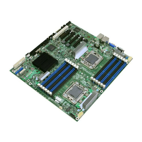
Intel® Server Boards S5520HC, S5500HCV, and S5520HCT TPS Overview Server Board Layout ® Figure 1. Intel Server Board S5520HC ® Figure 2. Intel Server Board S5500HCV 2.1.1 Server Board Connector and Component Layout The following figure shows the layout of the server board. Each connector and major component is identified by a number or letter, and a description is given below the figure. - Page 20 Type A USB Port Slot 4, PCI Express* Gen2 x8 SATA SGPIO Header ® Slot 5, PCI Express* Gen2 x8 (Empty on Intel SATA Port 0 Server Board S5500HCV) SATA Port 1 S5520HC: Slot 6, PCI Express* Gen2 x8 (x16 Revision 1.8...
-
Page 21: Figure 3. Major Board Components
Intel® Server Boards S5520HC, S5500HCV, and S5520HCT TPS Overview Callout Description Callout Description Mechanically) S5500HCV: Slot 6, PCI Express* Gen2 x4 (x16 Mechanically) Battery HSBP_B Back Panel I/O Ports SATA Port 2 Diagnostic and Identify LED’s HSBP_A System Fan 5 Header (4-pin) -
Page 22: Server Board Mechanical Drawings
Overview Intel® Server Boards S5520HC, S5500HCV, and S5520HCT TPS 2.1.2 Server Board Mechanical Drawings Figure 4. Mounting Hole Locations Revision 1.8 Intel order number E39529-013... -
Page 23: Figure 5. Major Connector Pin-1 Locations (1 Of 2)
Intel® Server Boards S5520HC, S5500HCV, and S5520HCT TPS Overview Figure 5. Major Connector Pin-1 Locations (1 of 2) Revision 1.8 Intel order number E39529-013... -
Page 24: Figure 6. Major Connector Pin-1 Locations (2 Of 2)
Overview Intel® Server Boards S5520HC, S5500HCV, and S5520HCT TPS Figure 6. Major Connector Pin-1 Locations (2 of 2) Revision 1.8 Intel order number E39529-013... -
Page 25: Figure 7. Primary Side Keep-Out Zone (1 Of 2)
Intel® Server Boards S5520HC, S5500HCV, and S5520HCT TPS Overview Figure 7. Primary Side Keep-out Zone (1 of 2) Revision 1.8 Intel order number E39529-013... -
Page 26: Figure 8. Primary Side Keep-Out Zone (2 Of 2)
Overview Intel® Server Boards S5520HC, S5500HCV, and S5520HCT TPS Figure 8. Primary Side Keep-out Zone (2 of 2) Revision 1.8 Intel order number E39529-013... -
Page 27: Figure 9. Primary Side Air Duct Keep-Out Zone
Intel® Server Boards S5520HC, S5500HCV, and S5520HCT TPS Overview Figure 9. Primary Side Air Duct Keep-out Zone Revision 1.8 Intel order number E39529-013... -
Page 28: Figure 10. Primary Side Card-Side Keep-Out Zone
Overview Intel® Server Boards S5520HC, S5500HCV, and S5520HCT TPS Figure 10. Primary Side Card-Side Keep-out Zone Revision 1.8 Intel order number E39529-013... -
Page 29: Figure 11. Second Side Keep-Out Zone
Intel® Server Boards S5520HC, S5500HCV, and S5520HCT TPS Overview Figure 11. Second Side Keep-out Zone Revision 1.8 Intel order number E39529-013... -
Page 30: Server Board Rear I/O Layout
Overview Intel® Server Boards S5520HC, S5500HCV, and S5520HCT TPS 2.1.3 Server Board Rear I/O Layout The following drawing shows the layout of the rear I/O components for the server boards. Callout Description Callout Description System Status LED Video NIC Port 1 (1 Gb, Default Management... -
Page 31: Functional Architecture
Intel® Server Boards S5520HC, S5500HCV, and S5520HCT TPS Functional Architecture Functional Architecture ® The architecture and design of the Intel Server Boards S5520HC, S5500HCV and ® S5520HCTis based on the Intel 5520/5500 and ICH10R chipset. The chipset is designed for ®... -
Page 32: Figure 13. Intel Server Board S5520Hc Functional Block Diagram
Functional Architecture Intel® Server Boards S5520HC, S5500HCV, and S5520HCT TPS ® Figure 13. Intel Server Board S5520HC Functional Block Diagram Revision 1.8 Intel order number E39529-013... -
Page 33: Figure 14. Intel Server Board S5500Hcv Functional Block Diagram
Intel® Server Boards S5520HC, S5500HCV, and S5520HCT TPS Functional Architecture ® Figure 14. Intel Server Board S5500HCV Functional Block Diagram Revision 1.8 Intel order number E39529-013... -
Page 34: Intel 5520 And 5500 I/O Hub (Ioh)
® The Intel 5520 and 5500 I/O Hub (IOH) in the Intel Server Boards S5520HC, S5500HCV and ® S5520HCT provide a connection point between various I/O components and Intel QPI-based processors, which includes the following core platform functions: • ®... -
Page 35: Enterprise South Bridge Interface (Esi)
Server Boards S5520HC, S5500HCV and S5520HCT. 3.1.4 Manageability Engine (ME) ® An embedded ARC controller is within the IOH providing the Intel Server Platform Services (SPS). The controller is also commonly referred to as the Manageability Engine (ME). 3.1.5 Controller Link (CL) The Controller Link is a private, low-pin count (LPC), low power, communication interface between the IOH and the ICH10 portions of the Manageability Engine subsystem. -
Page 36: Processor Support
QPI link interface and Thermal Design Power (TDP) up to 130 ® ® The server boards do not support previous generations of the Intel Xeon Processors. For a complete updated list of supported processors, see: http://support.intel.com/support/motherboards/server/S5520HC/. On the Support tab, look for “Compatibility”... -
Page 37: Table 2. Mixed Processor Configurations
Intel® Server Boards S5520HC, S5500HCV, and S5520HCT TPS Functional Architecture Table 2. Mixed Processor Configurations Error Severity System Action Processor family not Halt The BIOS detects the error condition and responds as follows: identical Logs the error into the system event log (SEL). -
Page 38: Intel ® Hyper-Threading Technology (Intel ® Ht)
The SMBIOS Type 4 structure shows only the installed physical processors. It does not describe the virtual processors. ® Because some operating systems are not able to efficiently use the Intel HT Technology, the BIOS does not create entries in the Multi-Processor Specification, Version 1.4 tables to describe the virtual processors. -
Page 39: Core Multi-Processing
Phillips* screwdriver to attach to the Unified Backplate Assembly. See the following figure for the stacking order of URS components. ® The Unified Backplate Assembly is removable, allowing for the use of non-Intel heatsink retention solutions. -
Page 40: Figure 15. Unified Retention System And Unified Back Plate Assembly
Functional Architecture Intel® Server Boards S5520HC, S5500HCV, and S5520HCT TPS Figure 15. Unified Retention System and Unified Back Plate Assembly Revision 1.8 Intel order number E39529-013... -
Page 41: Memory Subsystem
DIMMs on the server boards into autonomous memory. 3.3.1 Memory Subsystem Nomenclature ® The nomenclature for DIMM sockets implemented in the Intel Server Boards S5520HC, S5500HCV and S5520HCT is represented in the following figures. DIMMs are organized into physical slots on DDR3 memory channels that belong to processor sockets. -
Page 42: Figure 16. Intel
Functional Architecture Intel® Server Boards S5520HC, S5500HCV, and S5520HCT TPS Server Board CPU Socket DIMM Identifier Channel/Slot A1 (Blue) Channel A, Slot 0 A2 (Black) Channel A, Slot 1 B1 (Blue) Channel B, Slot 0 CPU 1 B2 (Black) Channel B, Slot 1... -
Page 43: Supported Memory
Intel® Server Boards S5520HC, S5500HCV, and S5520HCT TPS Functional Architecture Server Board CPU Socket DIMM Identifier Channel/Slot A1 (Blue) Channel A, Slot 0 A2 (Black) Channel A, Slot 1 B1 (Blue) Channel B, Slot 0 CPU 1 B2 (Black) Channel B, Slot 1 ®... -
Page 44: Processor Cores, Qpi Links And Ddr3 Channels Frequency Configuration
Mixing memory type, size, speed and/or rank on this platform has not been validated and is not supported Mixing memory vendors is not supported on this platform by Intel Non-ECC memory is not supported and has not been validated in a server environment ®... -
Page 45: Table 3. Memory Running Frequency Vs. Processor Sku
Intel® Server Boards S5520HC, S5500HCV, and S5520HCT TPS Functional Architecture Table 3. Memory Running Frequency vs. Processor SKU DIMM Type DDR3 800 DDR3 1066 DDR3 1333 Processor Integrated Memory Running Frequency Memory Controller (Hz) = Fastest Common 1066 1066 1066 (IMC) Max. -
Page 46: Publishing System Memory
When 4 GB or more of physical memory is installed (physical memory is the memory installed ® as DDR3 DIMMs), the reserved memory is lost. However, the Intel 5500/5520 I/O Hub provides a feature called high-memory reclaim, which allows the BIOS and the operating system to remap the lost physical memory into system memory above 4 GB (the system memory is the memory the processor can see). -
Page 47: Memory Test
Intel® Server Boards S5520HC, S5500HCV, and S5520HCT TPS Functional Architecture • Bank Interleaving – Interleave cache-line data between participant ranks. • Channel Interleaving – Interleave between channel when not in Mirrored Channel Mode. • Socket Interleaving – Interleaved memory can spread between both CPU sockets when NUMA mode is disabled, given both CPU sockets are populated and DDR3 DIMMs are installed in slots for both sockets. -
Page 48: Memory Population And Upgrade Rules
Moreover, it allows the best interleave mode possible and thereby increases performance and thermal characteristics. ® ® Adjacent slots on a DDR3 Channel from the Intel Xeon Processor 5500 series do not need matching size and organization in independent channel mode. However, the speed of the channel is configured to the maximum common speed of the DIMMs. - Page 49 Intel® Server Boards S5520HC, S5500HCV, and S5520HCT TPS Functional Architecture • ® ® Optimization techniques used by the Intel Xeon Processor 5500 Series to maximize memory bandwidth In the Independent Channel mode, all the DDR3 channels operate independently. Also, you can use the Independent Channel mode to support single DIMM configuration in Channel A and in the Single Channel mode.
-
Page 50: Supported Memory Configuration
3.3.10.1.1 Levels of support The following categories of memory configurations are supported: Supported – These configurations were verified by Intel to work but only limited validation was performed. Not all possible DDR3 DIMM configurations were validated due to the large number of possible configuration combinations. Supported configurations are highlighted in light gray in Tables 5 and 6. -
Page 51: Table 5. Supported Dimm Population Under The Dual Processors Configuration
Intel® Server Boards S5520HC, S5500HCV, and S5520HCT TPS Functional Architecture Table 5. Supported DIMM Population under the Dual Processors Configuration CPU1 Socket = Populated CPU2 Socket = Populated Table 6. Supported DIMM Population under the Single Processor Configuration CPU1 Socket = Populated... -
Page 52: Memory Error Handling
Functional Architecture Intel® Server Boards S5520HC, S5500HCV, and S5520HCT TPS 3.3.11 Memory Error Handling The BIOS classifies memory errors into the following categories: Correctable ECC errors: This correction could be the result of an ECC correction, a successfully retried memory cycle, or both. -
Page 53: Ich10R
Embedded Server RAID Technology II (Intel ESRTII) feature provides RAID modes ® ® 0, 1, and 10. If RAID 5 is needed with Intel ESRTII, you must install the optional Intel RAID Activation Key AXXRAKSW5 accessory. You must place this activation key on the SATA ®... -
Page 54: Revision 1.8
® implementation and provides the ability to use an Intel Embedded Server RAID Technology II ® volume as a boot disk and detect any faults in the Intel Embedded Server RAID Technology II volume(s). 3.4.1.2 Onboard SATA Storage Mode Matrix Table 7. -
Page 55: Usb 2.0 Support
One internal 2x5 header (J1D1) is provided, capable of supporting two optional USB 2.0 ports. ® • One internal 2x5 header (J1D2) is provided for Intel Server or Workstation chassis front panel USB ports, capable of supporting two optional USB 2.0 ports. •... -
Page 56: Pci Subsystem
Functional Architecture Intel® Server Boards S5520HC, S5500HCV, and S5520HCT TPS PCI Subsystem ® The primary I/O buses for the Intel Server Board S5520HC are PCI, PCI Express* Gen1, and PCI Express* Gen2 with six independent PCI bus segments. ® The primary I/O buses for the Intel Server Board S5500HCV are PCI, PCI Express* Gen1, and PCI Express* Gen2 with five independent PCI bus segments. -
Page 57: Pci Express* Riser Slot (S5520Hc - Slot 6)
Intel® Server Boards S5520HC, S5500HCV, and S5520HCT TPS Functional Architecture ® Table 9. Intel Server Board S5500HCV PCI Bus Segment Characteristics PCI Bus Segment Voltage Width Speed Type PCI I/O Card Slots PCI32 32 bit 33 MHz PCI Slot 1... -
Page 58: Intel Sas Entry Raid Module Axx4Sasmod (Optional Accessory)
® The Intel Server Boards S5520HC, S5500HCV and S5520HCT provide a Serial Attached SCSI ® (SAS) module slot (J2J1) for the installation of an optional Intel SAS Entry RAID Module ® AXX4SASMOD. Once the optional Intel SAS Entry RAID Module AXX4SASMOD is detected, the x4 PCI Express* links from the ICH10R to Slot 2 (x8 mechanically, x4 electrically) switches to the SAS module slot. -
Page 59: Sas Raid Support
SAS Entry RAID Module” option is enabled by default once the Intel SAS Entry ® RAID Module AXX4SASMOD is present. When enabled, you can set the “Configure Intel ® Entry RAID Module” to either “LSI* Integrated RAID” or “Intel ESRTII” mode. -
Page 60: Table 12. Intel Sas Entry Raid Module Axx4Sasmod Storage Mode
Embedded Server RAID Technology II (Intel ESRTII) feature provides RAID modes ® ® 0, 1, and 10. If RAID 5 is needed with Intel ESRTII, you must install the optional Intel RAID Activation Key AXXRAKSW5 accessory. This activation key is placed on the SAS Software ®... -
Page 61: Baseboard Management Controller
Intel® Server Boards S5520HC, S5500HCV, and S5520HCT TPS Functional Architecture Baseboard Management Controller ® The Intel Server Boards S5520HC, S5500HCV and S5520HCT have an integrated BMC controller based on ServerEngines* Pilot II. The BMC controller is provided by an embedded ARM9 controller and associated peripheral functionality that is required for IPMI-based server management. -
Page 62: Bmc Embedded Lan Channel
Functional Architecture Intel® Server Boards S5520HC, S5500HCV, and S5520HCT TPS Figure 20. Integrated BMC Hardware 3.7.1 BMC Embedded LAN Channel The BMC hardware includes two dedicated 10/100 network interfaces, which are given below: Interface 1: This interface is available from either of the available NIC ports in system that can be shared with the host. -
Page 63: Serial Ports
Intel® Server Boards S5520HC, S5500HCV, and S5520HCT TPS Functional Architecture Serial Ports ® The Intel Server Boards S5520HC, S5500HCV and S5520HCT provide two serial ports: an external DB9 serial port and an internal DH-10 serial header. The rear DB9 serial A port is a fully-functional serial port that can support any standard serial device. -
Page 64: Dual Video
Functional Architecture Intel® Server Boards S5520HC, S5500HCV, and S5520HCT TPS Table 14. Video Modes 2D Video Mode Support 2D Mode 8 bpp 16 bpp 24 bpp 32 bpp Supported Supported Supported Supported 640 x 480 Refresh Rate 60, 72, 75, 85... -
Page 65: Network Interface Controller (Nic)
During the manufacturing process, each server board has a white MAC address sticker placed ® on the top of the NIC 1 port. The sticker displays the NIC 1 MAC address and Intel RMM3 MAC in both bar code and alphanumeric formats. -
Page 66: 3.13 *Trusted Platform Module (Tpm) - Supported Only On S5520Hct
A TPM device provides secured storage to store data, such as security keys and ® passwords. In addition, a TPM device has encryption and hash functions. The Intel Server Board S5520HCT implements TPM as per TPM PC Client specifications revision 1.2 by the Trusted Computing Group (TCG). - Page 67 The Security screen provides fields to enable and set the user and administrative passwords ® and to lock out the front panel buttons so they cannot be used. The Intel Server Board S5520HCT provides TPM settings through the security screen.
-
Page 68: Figure 21. Setup Utility - Tpm Configuration Screen
Functional Architecture Intel® Server Boards S5520HC, S5500HCV, and S5520HCT TPS Main Advanced Security Server Management Boot Options Boot Manager Administrator Password Status <Installed/Not Installed> User Password Status <Installed/Not Installed> Set Administrator Password [1234aBcD] Set User Password [1234aBcD] Front Panel Lockout Enabled/Disabled <Enabled &... -
Page 69: Txt)
In turn, this can help to protect vital data and processes from being compromised by malicious software running on the platform. Long available on client platforms, Intel is now enabling Intel TXT on selected server platforms as well. ®... -
Page 70: Figure 22. Setting Administrator Password In Bios
Functional Architecture Intel® Server Boards S5520HC, S5500HCV, and S5520HCT TPS System pre-requirements: ® Processor: B1 or later stepping Intel Xeon Processor 5600 Series ® Server Board: Intel Server Board S5520HCT; PBA version E80888-553 or later Memory: At least 1 GB memory installed ®... -
Page 71: Figure 23. Activating Tpm
Intel® Server Boards S5520HC, S5500HCV, and S5520HCT TPS Functional Architecture Figure 23. Activating TPM 4. Go to BIOS setup Menu, Security Tab, TPM State should be “Enabled & Activated”. Revision 1.8 Intel order number E39529-013... -
Page 72: Figure 24. Tpm Activated
Functional Architecture Intel® Server Boards S5520HC, S5500HCV, and S5520HCT TPS Figure 24. TPM activated 5. Go to BIOS Setup Menu, Advanced -> Processor Configuration, set Intel ® VT for directed I/O and Intel ® TXT option as “Enabled” Revision 1.8... -
Page 73: 3.14 Acpi Support
Intel® Server Boards S5520HC, S5500HCV, and S5520HCT TPS Functional Architecture Figure 25. BIOS setting for TXT ® 6. Press “F10” to save and exit, now Intel TXT is successfully enabled. 3.14 ACPI Support ® The Intel Server Boards S5520HC, S5500HCV and S5520HCT support S0, S1, and S5 states. -
Page 74: Intel ® Virtualization Technology
Virtualization Technology is designed to support multiple software environments sharing the same hardware resources. Each software environment may consist of an operating system ® and applications. You can enable or disable the Intel Virtualization Technology in the BIOS Setup. The default behavior is disabled. -
Page 75: Platform Management
Intel® Server Boards S5520HC, S5500HCV, and S5520HCT TPS Platform Management Platform Management The platform management subsystem is based on the Integrated BMC features of the ServerEngines* Pilot II. The onboard platform management subsystem consists of communication buses, sensors, and the system BIOS, and server management firmware. - Page 76 Platform Management Intel® Server Boards S5520HC, S5500HCV, and S5520HCT TPS • Fault resilient booting (FRB): FRB2 is supported by the watchdog timer functionality. • Chassis intrusion detection (dependant on platform support) • Basic fan control using TControl version 2 SDRs •...
-
Page 77: Optional Advanced Management Feature Support
Intelligent Power Node Manager Support requires PMBus-compliant power supply 4.2.1 Enabling Advanced Management Features ® BMC will enable advanced management features only when it detects the presence of the Intel ® ® Remote Management Module 3 (Intel RMM3) card. Without the Intel RMM3, the advanced features are dormant. -
Page 78: Media Redirection
Platform Management Intel® Server Boards S5520HC, S5500HCV, and S5520HCT TPS (JRE6) or later to run the KVM or media redirection applets. You can download the latest Java Runtime Environment (JRE) update: http://java.com/en/download/index.jsp. ® This feature is only enabled when the Intel RMM3 is present. -
Page 79: Web Services For Management (Ws-Man)
Intel® Server Boards S5520HC, S5500HCV, and S5520HCT TPS Platform Management • You can mount either IDE (CD-ROM, floppy) or USB devices as a remote device to the server. • It is possible to boot all supported operating systems from the remotely mounted device and to boot from disk IMAGE (*.IMG) and CD-ROM or DVD-ROM ISO files. -
Page 80: Embedded Web Server
Platform Management Intel® Server Boards S5520HC, S5500HCV, and S5520HCT TPS 4.2.5 Embedded Web server The BMC provides an embedded web server for out-of-band management. User authentication is handled by IPMI user names and passwords. Base functionality for the embedded web server includes: •... -
Page 81: Platform Control
Intel® Server Boards S5520HC, S5500HCV, and S5520HCT TPS Platform Management Platform Control This server platform has embedded platform control which is capable of automatically adjusting system performance and acoustic levels. Figure 26. Platform Control Platform control optimizes system performance and acoustics levels through: •... -
Page 82: Memory Open And Closed Loop Thermal Throttling
NVRAM on the server board. It allows the user to select which supported chassis (Intel or Non-Intel) and platform chassis configuration is used. Based on the input provided, the FRUSDR writes sensor data specific to the configuration to NVRAM for the BMC controller to read each time the system is powered on. -
Page 83: Table 18. S5520Hc, S5500Hcv And S5520Hct Fan Domain Table
Intel® Server Boards S5520HC, S5500HCV, and S5520HCT TPS Platform Management BIOS fails to get the Thermal SDRs, then it uses the Memory Reference Code (MRC) default settings for the memory throttling settings. The <F2> BIOS Setup Utility provides options to set the fan profile or operating mode the platform will operate under. -
Page 84: Intel ® Intelligent Power Node Manager
Note: Fan speed control for a non-Intel chassis, as configured after running the FRUSDR utility and selecting the Non-Intel Chassis option, is limited to only the CPU fans. The BMC only requires the processor thermal sensor data to determine how fast to operate these fans. The remaining system fans will operate at 100% operating limits due to unknown variables associated with the given chassis and its fans. -
Page 85: Figure 27. Smbus Block Diagram
Intel® Server Boards S5520HC, S5500HCV, and S5520HCT TPS Platform Management Figure 27. SMBUS Block Diagram Revision 1.8 Intel order number E39529-013... -
Page 86: Bios Setup Utility
• Platform name • Total memory detected (Total size of all installed DDR3 DIMMs) • Processor information (Intel branded string, speed, and number of physical processors identified) • Keyboards detected (if plugged in) • Mouse devices detected (if plugged in) -
Page 87: Table 19. Bios Setup Page Layout
5.3.1.2 Entering BIOS Setup To enter the BIOS Setup, press the F2 function key during boot time when the OEM or Intel logo displays. The following message displays on the diagnostics screen and under the Quiet Boot logo screen: Press <F2>... -
Page 88: Table 20. Bios Setup: Keyboard Command Bar
BIOS Setup Utility Intel® Server Boards S5520HC, S5500HCV, and S5520HCT TPS Table 20. BIOS Setup: Keyboard Command Bar Option Description Execute The <Enter> key is used to activate sub-menus when the selected feature is a sub- <Enter> Command menu, or to display a pick list if a selected option has a value field, or to select a sub-field for multi-valued features like time and date. -
Page 89: Server Platform Setup Utility Screens
Intel® Server Boards S5520HC, S5500HCV, and S5520HCT TPS BIOS Setup Utility 5.3.1.4 Menu Selection Bar The Menu Selection Bar is located at the top of the BIOS Setup Utility screen. It displays the major menu selections available to the user. By using the left and right arrow keys, the user can select the menus listed here. -
Page 90: Figure 28. Setup Utility - Main Screen Display
BIOS Setup Utility Intel® Server Boards S5520HC, S5500HCV, and S5520HCT TPS 5.3.2.1 Main Screen Unless an error occurred, the Main screen is the first screen displayed when the BIOS Setup is entered. If an error occurred, the Error Manager screen displays instead. - Page 91 Intel® Server Boards S5520HC, S5500HCV, and S5520HCT TPS BIOS Setup Utility Setup Item Options Help Text Comments Size Information only. Displays the total physical memory installed in the system, in MB or GB. The term physical memory indicates the total memory discovered in the form of installed DDR3 DIMMs.
-
Page 92: Figure 29. Setup Utility - Advanced Screen Display
BIOS Setup Utility Intel® Server Boards S5520HC, S5500HCV, and S5520HCT TPS 5.3.2.2 Advanced Screen The Advanced screen provides an access point to configure several options. On this screen, the user selects the option they must configure. Configurations are performed on the selected screen and not directly on the Advanced screen. -
Page 93: Figure 30. Setup Utility - Processor Configuration Screen Display
Intel® Server Boards S5520HC, S5500HCV, and S5520HCT TPS BIOS Setup Utility 5.3.2.2.1 Processor Configuration Screen The Processor screen allows the user to view the processor core frequency, system bus frequency, and to enable or disable several processor options. This screen also allows the user to view information about a specific processor. -
Page 94: Table 23. Setup Utility - Processor Configuration Screen Fields
BIOS Setup Utility Intel® Server Boards S5520HC, S5500HCV, and S5520HCT TPS Table 23. Setup Utility — Processor Configuration Screen Fields Setup Item Options Help Text Comments Processor ID Information only. Processor CPUID Processor Frequency Information only. Current frequency of the processor. - Page 95 Intel® Server Boards S5520HC, S5500HCV, and S5520HCT TPS BIOS Setup Utility Setup Item Options Help Text Comments ® ® Intel Virtualization Enabled Enable/Disable Intel Virtualization Technology for Directed Technology for Directed I/O. Disabled Report the I/O device assignment to VMM through DMAR ACPI Tables ®...
-
Page 96: Figure 31. Setup Utility - Memory Configuration Screen Display
BIOS Setup Utility Intel® Server Boards S5520HC, S5500HCV, and S5520HCT TPS 5.3.2.2.2 Memory Screen The Memory screen allows the user to view details about the system memory DDR3 DIMMs installed. This screen also allows the user to open the Configure Memory RAS and Performance screen. -
Page 97: Table 24. Setup Utility - Memory Configuration Screen Fields
Intel® Server Boards S5520HC, S5500HCV, and S5520HCT TPS BIOS Setup Utility Table 24. Setup Utility — Memory Configuration Screen Fields Setup Item Options Help Text Comments Total Memory Information only. The amount of memory available in the system in the form of... -
Page 98: Figure 32. Setup Utility - Configure Ras And Performance Screen Display
BIOS Setup Utility Intel® Server Boards S5520HC, S5500HCV, and S5520HCT TPS 5.3.2.2.2.1 Configure Memory RAS and Performance Screen The Configure Memory RAS and Performance screen allows the user to customize several memory configuration options, such as whether to use Memory Mirroring. -
Page 99: Figure 33. Setup Utility - Mass Storage Controller Configuration Screen Display
Mass Storage Controller Screen The Mass Storage screen allows the user to configure the SATA/SAS controller when it is present on the baseboard module card of an Intel system. To access this screen from the Main menu, select Advanced > Mass Storage. -
Page 100: Table 26. Setup Utility - Mass Storage Controller Configuration Screen Fields
BIOS Setup Utility Intel® Server Boards S5520HC, S5500HCV, and S5520HCT TPS Table 26. Setup Utility — Mass Storage Controller Configuration Screen Fields Setup Item Options Help Text Comments ® ® Intel Entry SAS RAID Enabled or Disable the Intel SAS Entry RAID... -
Page 101: Figure 34. Setup Utility - Serial Port Configuration Screen Display
Intel® Server Boards S5520HC, S5500HCV, and S5520HCT TPS BIOS Setup Utility 5.3.2.2.4 Serial Ports Screen The Serial Ports screen allows the user to configure the Serial A [COM 1] and Serial B [COM2] ports. To access this screen from the Main screen, select Advanced > Serial Port. -
Page 102: Figure 35. Setup Utility - Usb Controller Configuration Screen Display
BIOS Setup Utility Intel® Server Boards S5520HC, S5500HCV, and S5520HCT TPS 5.3.2.2.5 USB Configuration Screen The USB Configuration screen allows the user to configure the USB controller options. To access this screen from the Main screen, select Advanced > USB Configuration. -
Page 103: Table 28. Setup Utility - Usb Controller Configuration Screen Fields
Intel® Server Boards S5520HC, S5500HCV, and S5520HCT TPS BIOS Setup Utility Table 28. Setup Utility — USB Controller Configuration Screen Fields Setup Item Options Help Text Comments Detected USB Information only. Shows the Devices number of USB devices in the system. -
Page 104: Figure 36. Setup Utility - Pci Configuration Screen Display
BIOS Setup Utility Intel® Server Boards S5520HC, S5500HCV, and S5520HCT TPS 5.3.2.2.6 PCI Screen The PCI Screen allows the user to configure the PCI add-in cards, onboard NIC controllers, and video options. To access this screen from the Main screen, select Advanced > PCI. -
Page 105: Figure 37. Setup Utility - System Acoustic And Performance Configuration Screen Display
Intel® Server Boards S5520HC, S5500HCV, and S5520HCT TPS BIOS Setup Utility Setup Item Options Help Text Comments Onboard NIC iSCSI Enabled If enabled. loads the embedded option ROM for This option is grayed out the onboard network controllers. and not accessible if either... -
Page 106: Figure 38. Setup Utility - Security Configuration Screen Display
BIOS Setup Utility Intel® Server Boards S5520HC, S5500HCV, and S5520HCT TPS Table 30. Setup Utility — System Acoustic and Performance Configuration Screen Fields Setup Item Options Help Text Comments Set Throttling [Auto] – Auto Throttling mode. Auto Mode CLTT [CLTT] – Closed Loop Thermal Throttling Mode. -
Page 107: Table 31. Setup Utility - Security Configuration Screen Fields
Intel® Server Boards S5520HC, S5500HCV, and S5520HCT TPS BIOS Setup Utility Table 31. Setup Utility — Security Configuration Screen Fields Setup Item Options Help Text Comments Administrator Password <Installed Information only. Indicates Status the status of the Not Installed> administrator password. - Page 108 BIOS Setup Utility Intel® Server Boards S5520HC, S5500HCV, and S5520HCT TPS Setup Item Options Help Text Comments TPM Administrative [No Operation] - No changes to No Operation Control** current state. Turn On [Turn On] - Enables and Turn Off activates TPM.
-
Page 109: Figure 39. Setup Utility - Server Management Configuration Screen Display
Intel® Server Boards S5520HC, S5500HCV, and S5520HCT TPS BIOS Setup Utility Main Advanced Security Server Management Boot Options Boot Manager Assert NMI on SERR Enabled/Disabled Assert NMI on PERR Enabled/Disabled Resume on AC Power Loss Stay Off/Last state/Reset Clear System Event Log... -
Page 110: Figure 40. Setup Utility - Console Redirection Screen Display
BIOS Setup Utility Intel® Server Boards S5520HC, S5500HCV, and S5520HCT TPS Setup Item Options Help Text Comments O/S Boot Watchdog Enabled If enabled, the BIOS programs the watchdog timer Timer with the timeout value selected. If the OS does not... -
Page 111: Table 33. Setup Utility - Console Redirection Configuration Fields
Intel® Server Boards S5520HC, S5500HCV, and S5520HCT TPS BIOS Setup Utility Table 33. Setup Utility — Console Redirection Configuration Fields Setup Item Options Help Text Console Redirection Console redirection allows a serial port to be used for Disabled server management tasks. -
Page 112: Figure 41. Setup Utility - Server Management System Information Screen Display
BIOS Setup Utility Intel® Server Boards S5520HC, S5500HCV, and S5520HCT TPS Server Management System Information Board Part Number Board Serial Number System Part Number System Serial Number Chassis Part Number Chassis Serial Number Asset Tag BMC Firmware Revision HSC Firmware Revision... -
Page 113: Figure 42. Setup Utility - Boot Options Screen Display
Intel® Server Boards S5520HC, S5500HCV, and S5520HCT TPS BIOS Setup Utility Main Advanced Security Server Management Boot Options Boot Manager System Boot Timeout <0 - 65535> Boot Option #1 <Available Boot devices> Boot Option #2 <Available Boot devices> Boot Option #x <Available Boot devices>... -
Page 114: Table 35. Setup Utility - Boot Options Screen Fields
BIOS Setup Utility Intel® Server Boards S5520HC, S5500HCV, and S5520HCT TPS Table 35. Setup Utility — Boot Options Screen Fields Setup Item Options Help Text Comments After entering the necessary Boot Timeout 0 - 65535 The number of seconds the BIOS should pause at... -
Page 115: Figure 43. Setup Utility - Add New Boot Option Screen Display
Intel® Server Boards S5520HC, S5500HCV, and S5520HCT TPS BIOS Setup Utility If all types of bootable devices are installed in the system, then the default boot order is: 1. CD/DVD-ROM 2. Floppy Disk Drive 3. Hard Disk Drive 4. PXE Network Device 5. -
Page 116: Figure 44. Setup Utility - Delete Boot Option Screen Display
BIOS Setup Utility Intel® Server Boards S5520HC, S5500HCV, and S5520HCT TPS 5.3.2.6.2 Delete Boot Option Screen The Delete Boot Option screen allows the user to remove an EFI boot option from the boot order. Note that while you can delete the Internal EFI Shell in this screen, it is restored to the Boot Order on the next reboot. -
Page 117: Figure 46. Setup Utility - Cdrom Order Screen Display
Intel® Server Boards S5520HC, S5500HCV, and S5520HCT TPS BIOS Setup Utility 5.3.2.6.4 CDROM Order Screen The CDROM Order screen allows the user to control the CDROM devices. To access this screen from the Main screen, select Boot Options > CDROM Order. -
Page 118: Figure 48. Setup Utility - Network Device Order Screen Display
BIOS Setup Utility Intel® Server Boards S5520HC, S5500HCV, and S5520HCT TPS Setup Item Options Help Text Floppy Disk #2 Available Set system boot order by selecting the boot Legacy devices option for this position. for this Device group. 5.3.2.6.6 Network Device Order Screen The Network Device Order screen allows the user to control the network bootable devices. -
Page 119: Figure 50. Setup Utility - Boot Manager Screen Display
Intel® Server Boards S5520HC, S5500HCV, and S5520HCT TPS BIOS Setup Utility Table 42. Setup Utility — BEV Device Order Fields Setup Item Options Help Text BEV Device #1 Available Set system boot order by selecting the boot Legacy devices option for this position. -
Page 120: Figure 51. Setup Utility - Error Manager Screen Display
BIOS Setup Utility Intel® Server Boards S5520HC, S5500HCV, and S5520HCT TPS 5.3.2.8 Error Manager Screen The Error Manager screen displays any errors encountered during POST. Error Manager Exit ERROR CODE SEVERITY INSTANCE Figure 51. Setup Utility — Error Manager Screen Display Table 44. -
Page 121: Table 45. Setup Utility - Exit Screen Fields
Intel® Server Boards S5520HC, S5500HCV, and S5520HCT TPS BIOS Setup Utility Table 45. Setup Utility — Exit Screen Fields Setup Item Help Text Comments Save Changes and Exit Exit the BIOS Setup utility after saving changes. User prompted for confirmation only if The system reboots if required. -
Page 122: Connector/Header Locations And Pin-Outs
Connector/Header Locations and Pin-outs Intel® Server Boards S5520HC, S5500HCV, and S5520HCT TPS Connector/Header Locations and Pin-outs Board Connector Information The following section provides detailed information regarding all connectors, headers, and jumpers on the server boards. The following table lists all connector types available on the board and the corresponding preference designators printed on the silkscreen. -
Page 123: Power Connectors
Intel® Server Boards S5520HC, S5500HCV, and S5520HCT TPS Connector/Header Locations and Pin-outs Connector Quantity Reference Designators Connector Type Pin Count J1E6 (CMOS Clear), J1E2 (ME Force Update), J1E4 (Password Clear), J1E5 Configuration jumpers 4 Jumper (BIOS Recovery), J1H1 (BMC Force... -
Page 124: System Management Headers
Intel Remote Management Module 3. These server boards do not support third-party management cards. ® ® Note: This connector is not compatible with the Intel Remote Management Module (Intel ® ® RMM) or the Intel Remote Management Module 2 (Intel RMM2). -
Page 125: Lcp/Ipmb Header
SGPIO_DATAOUT1 SGPIO Data In Front Panel Connector ® The server boards provide a 24-pin SSI front panel connector (J1B3) for use with Intel third-party chassis. The following table provides the pin-out for this connector: Revision 1.8 Intel order number E39529-013... -
Page 126: I/O Connectors
Connector/Header Locations and Pin-outs Intel® Server Boards S5520HC, S5500HCV, and S5520HCT TPS Table 55. Front Panel SSI Standard 24-pin Connector Pin-out (J1B3) Signal Name Description Signal Name Description P3V3_STBY Power LED + P3V3_STBY Front Panel (Power_LED_Anode) Power No Connection P5V_STBY (ID... -
Page 127: Nic Connectors
Positive side of receive differential pair Ground 6.5.4 SAS Module Slot ® The server boards provide one SAS module slot (J2J1) to support the Intel SAS Entry RAID Module AXX4SASMOD card. The following table defines the pin-out: Table 59. SAS Module Slot Pin-out (J2J1) Name... -
Page 128: Serial Port Connectors
Connector/Header Locations and Pin-outs Intel® Server Boards S5520HC, S5500HCV, and S5520HCT TPS Name Name PE_ICH10_SAS_SW_C_TP1 PE_ICH10_SAS_SW_C_TN1 PE_ICH10_SAS_SW_C_TN2 PE_ICH10_SAS_SW_C_TN2 PE_ICH10_SAS_SW_C_TN3 PE_ICH10_SAS_SW_C_TN3 FM_SAS_PRSNT_N PE_WAKE_N FM_SAS_RST_N P3V3 PE_RXN<2> P3V3 P3V3_AUX PE_ICH10_SAS_SW_RXP0 PE_ICH10_SAS_SW_RXN0 PE_ICH10_SAS_SW_RXP1 PE_ICH10_SAS_SW_RXN1 PE_ICH10_SAS_SW_RXP2 PE_ICH10_SAS_SW_RXN2 PE_ICH10_SAS_SW_RXP3 PE_ICH10_SAS_SW_RXN3 CLK_100M_SAS_DP CLK_100M_SAS_DN P3V3 P3V3 P3V3 6.5.5... -
Page 129: Usb Connector
Intel® Server Boards S5520HC, S5500HCV, and S5520HCT TPS Connector/Header Locations and Pin-outs 6.5.6 USB Connector The following table details the pin-out of the external USB connectors (J5A1, J6A1) found on the back edge of the server boards. Table 62. External USB Connector Pin-out (J5A1, J6A1) -
Page 130: Fan Headers
Connector/Header Locations and Pin-outs Intel® Server Boards S5520HC, S5500HCV, and S5520HCT TPS Table 65. Pin-out of Internal Low-Profile USB Connector for Solid State Drive (J2D2) Signal Name Description USB_PWR11_5V USB power Not Connected USB Data - USB port 11 negative signal... -
Page 131: Table 67. Ssi 4-Pin Fan Header Pin-Out (J7K1, J9A2, J9A3)
VLSI and power delivery components that need adequate airflow to cool. Intel’s own chassis are designed and tested to meet the intended thermal requirements of these components when the fully integrated system is used together. It is the responsibility of the ®... -
Page 132: Jumper Blocks
Jumper Blocks Intel® Server Boards S5520HC, S5500HCV, and S5520HCT TPS Jumper Blocks The server boards have several 3-pin jumper blocks that you can use to configure, protect, or recover specific features of the server boards. The following symbol identifies Pin 1 on each jumper block on the silkscreen: ▼... -
Page 133: Cmos Clear And Password Reset Usage Procedure
Intel® Server Boards S5520HC, S5500HCV, and S5520HCT TPS Jumper Blocks CMOS Clear and Password Reset Usage Procedure The CMOS Clear (J1E6) and Password Reset (J1E4) recovery features are designed to achieve the desired operation with minimum system down time. The usage procedure for these two ®... -
Page 134: Force Bmc Update Procedure
Jumper Blocks Intel® Server Boards S5520HC, S5500HCV, and S5520HCT TPS Force BMC Update Procedure When performing a standard BMC firmware update procedure, the update utility places the BMC into an update mode, allowing the firmware to load safely onto the flash device. In the... - Page 135 Intel® Server Boards S5520HC, S5500HCV, and S5520HCT TPS Jumper Blocks 8. Power down the system and remove the AC power cord. 9. Open the server chassis. 10. Move the BIOS recovery jumper (J1E5) from the “enabled” position (covering pins 2 and 3) to the “disabled”...
-
Page 136: Intel Light Guided Diagnostics
Intel® Light Guided Diagnostics Intel® Server Boards S5520HC, S5500HCV, and S5520HCT TPS Intel Light Guided Diagnostics ® Both server boards have several onboard diagnostic LEDs to assist in troubleshooting board- level issues. This section provides a description of the location and function of each LED on the server boards. -
Page 137: Fan Fault Led's
Intel® Server Boards S5520HC, S5500HCV, and S5520HCT TPS Intel® Light Guided Diagnostics Fan Fault LED’s Fan fault LEDs are present for the two CPU fans and the one rear system fan. The fan fault LEDs illuminate when the corresponding fan has fault. -
Page 138: System Id Led And System Status Led
Intel® Light Guided Diagnostics Intel® Server Boards S5520HC, S5500HCV, and S5520HCT TPS System ID LED and System Status LED The server boards provide LEDs for both system ID and system status. These LEDs are located in the rear I/O area of the server board as shown in the following figure. -
Page 139: Table 70. System Status Led
Intel® Server Boards S5520HC, S5500HCV, and S5520HCT TPS Intel® Light Guided Diagnostics • By issuing the appropriate hex IPMI “Chassis Identify” value, the ID LED will either blink blue for 15 seconds and turn off or will blink indefinitely until the appropriate hex IPMI Chassis Identify value is issue to turn it off. -
Page 140: Dimm Fault Leds
The DIMM fault LED illuminates when the corresponding DIMM slot has memory installed and a memory error occurs. * D2, E2, and F2 DIMM slot and Fault LED’s are empty in Intel Server Board S5500HCV ®... -
Page 141: Post Code Diagnostic Leds
Intel® Server Boards S5520HC, S5500HCV, and S5520HCT TPS Intel® Light Guided Diagnostics Post Code Diagnostic LEDs Eight amber POST code diagnostic LEDs are located on the back edge of the server boards in the rear I/O area of the server boards by the serial A connector. -
Page 142: Design And Environmental Specifications
Chassis design must provide proper airflow to avoid exceeding the processor maximum case temperature. Disclaimer Note: Intel Corporation server boards contain a number of high-density VLSI and power delivery components that need adequate airflow to cool. Intel ensures through its own ® chassis development and testing that when Intel server building blocks are used together, the fully integrated system will meet the intended thermal requirements of these components. -
Page 143: Table 72. Mtbf Estimate
Intel® Server Boards S5520HC, S5500HCV, and S5520HCT TPS Design and Environmental Specifications • Duty Cycle: 100% • Quality Level: II Table 72. MTBF Estimate S5520HC MTBF S5500HCV MTBF Ambient Air Temperature (ºC) Air Temp. at Board for 10(ºC) rise (ºC) -
Page 144: Server Board Power Requirements
Intel® Server Board S5520HC and S5520HCS5500HCV TPS Server Board Power Requirements ® This section provides power supply design guidelines for a system using the Intel Server Boards S5520HC, S5500HCV and S5520HCT including voltage and current specifications, and power supply on/off sequencing characteristics. The following diagram shows the power distribution implemented on these server boards. -
Page 145: Processor Power Support
This section specifies the power supply requirements Intel used to develop a power supply for its 5U server system. The combined power of all outputs should not exceed the rated output power of the power supply. -
Page 146: Remote Sense
Design and Environmental Specifications Intel® Server Boards S5520HC, S5500HCV, and S5520HCT TPS 9.4.3 Remote Sense The power supply should have remote sense return (ReturnS) to regulate out ground drops for all output voltages: +3.3 V, +5 V, +12 V1, +12 V2, +12 V3, +12 V4, -12 V, and 5 VSB. The power supply should use remote sense to regulate out drops in the system for the +3.3 V, +5 V,... -
Page 147: Capacitive Loading
Intel® Server Boards S5520HC, S5500HCV, and S5520HCT TPS Design and Environmental Specifications Table 76. Transient Load Requirements Output Δ Step Load Size 1 Load Slew Rate Test Capacitive Load +3.3 V 7.0 A 0.25A/μsec 4700μF +5 V 7.0 A 0.25A/μsec 1000μF... -
Page 148: Figure 60. Output Voltage Timing
Design and Environmental Specifications Intel® Server Boards S5520HC, S5500HCV, and S5520HCT TPS Table 79. Output Voltage Timing Item Description Minimum Maximum Units Tvout_rise Output voltage rise time from each main output. 5.0 1 70 1 Tvout_rise All main outputs must be within regulation of each other within this time. -
Page 149: Figure 61. Turn On/Off Timing (Power Supply Signals)
Intel® Server Boards S5520HC, S5500HCV, and S5520HCT TPS Design and Environmental Specifications Table 80. Turn On/Off Timing Item Description Minimum Maximum Units Tsb_on_delay Delay from AC being applied to 5 VSB being within 1500 regulation. Tac_on_delay Delay from AC being applied to all output voltages being 2500 within regulation. -
Page 150: Residual Voltage Immunity In Stand-By Mode
Design and Environmental Specifications Intel® Server Boards S5520HC, S5500HCV, and S5520HCT TPS 9.4.9 Residual Voltage Immunity in Stand-by Mode The power supply should be immune to any residual voltage placed on its outputs (typically, a leakage voltage through the system from stand-by output) up to 500 mV. There should be no additional heat generated or stressing of any internal components with this voltage applied to any individual output and all outputs simultaneously. -
Page 151: 10. Regulatory And Certification Information
EMC compliance testing. For more information, please contact your local Intel Representative. This is an FCC Class A device. Integration of it into a Class B chassis does not result in a Class B device. -
Page 152: Certifications/Registrations/Declarations
Regulatory and Certification Information Intel® Server Boards S5520HC, S5500HCV, and S5520HCT TPS • BSMI CNS13438 Emissions (Taiwan) • RRL Notice No. 1997-41 (EMC) & 1997-42 (EMI) (Korea) • GOST R 29216-91 Emissions (Russia) – Listed on System License • GOST R 50628-95 Immunity (Russia) – Listed on System License •... -
Page 153: 10.3 Electromagnetic Compatibility Notices
Intel® Server Boards S5520HC, S5500HCV, and S5520HCT TPS Regulatory and Certification Information Identification PB number for non-boxed boards (typically high-end boards) 10.3 Electromagnetic Compatibility Notices FCC (USA) This device complies with Part 15 of the FCC Rules. Operation is subject to the following two conditions: (1) this device may not cause harmful interference, and (2) this device must accept any interference received, including interference that may cause undesired operation. -
Page 154: Ices-003 (Canada)
Regulatory and Certification Information Intel® Server Boards S5520HC, S5500HCV, and S5520HCT TPS ICES-003 (Canada) Cet appareil numérique respecte les limites bruits radioélectriques applicables aux appareils numériques de Classe A prescrites dans lanorme sur le matériel brouilleur: “Apparelis Numériques”, NMB-003 édictee par le Ministre Canadian des Communications. -
Page 155: Rrl Kcc (Korea)
RRL KCC (Korea) 10.4 Product Ecology Change (EU RoHS) Intel has a system in place to restrict the use of banned substances in accordance with the European Directive 2002/95/EC. Compliance is based on declaration that materials banned in the RoHS Directive are either (1) below all applicable threshold limits or (2) an approved/pending RoHS exemption applies. - Page 156 Intel® Server Boards S5520HC, S5500HCV, and S5520HCT TPS CRoHS Substance Tables: China CRoHS requires products to be provided with controlled substance information. Intel understands the end-seller (entity placing product into market place) is responsible for providing the controlled substance information. Controlled substance information is required to be in Simplified Chinese.
- Page 157 Intel® Server Boards S5520HC, S5500HCV, and S5520HCT TPS Regulatory and Certification Information Revision 1.8 Intel order number E39529-013...
-
Page 158: China Packaging Recycle Marks (Or Gb18455-2001)
The State of California requires a warning to be included for products containing a device using Lithium Perchlorate. Intel understands CA Lithium Perchlorate require a printed warning to be included with all products containing a Lithium battery, either as an insert, in existing product literature, or as part of the shipping memo wording. -
Page 159: Appendix A: Integration And Usage Tips
Intel® Server Boards S5520HC, S5500HCV, and S5520HCT TPS Appendix A: Integration and Usage Tips Appendix A: Integration and Usage Tips • Prior to adding or removing components or peripherals from the server board, you must remove the AC power cord. With AC power plugged into the server board, 5-V standby is still present even though the server board is powered off. - Page 160 Appendix A: Integration and Usage Tips Intel® Server Boards S5520HC, S5500HCV, and S5520HCT TPS Step 2: Decide the PCI device with location number (Bus number, Device number, and Function number) using PCI map dump from the system generating the PCI device SEL event, There are multiple means to dump the PCI map.
-
Page 161: Appendix B: Compatible Intel Server Chassis
Refer to the following table for the compatible Intel Server Chassis of Intel Server Boards S5520HC, S5500HCV and S5520HCT: ® Passive tower processor heatsink(s) (product code: FXXRGTHSINK) is required when installing the Intel Server Board S5520HC or ® S5500HCV in the Intel Server Chassis SC5600LX. - Page 162 Appendix B: Compatible Intel® Server Chassis Intel® Server Boards S5520HC, S5500HCV, and S5520HCT TPS Intel ® Thermal Solution FXXRGTHSINK Intel ® Thermal Solution S5520HC S5500HCV Chassis SKU Heatsink Includes STS100C (w/ fan, Active STS100A (Active) (Passive Tower Heatsink) mode) Chassis...
-
Page 163: Figure 62. Active Processor Heatsink Installation Requirement
Intel® Server Boards S5520HC, S5500HCV and S5520HCT TPS Appendix B: Compatible Intel® Server Chassis Figure 62. Active Processor Heatsink Installation Requirement Revision 1.8 Intel order number E39529-013... -
Page 164: Appendix C: Bmc Sensor Tables
Appendix C: BMC Sensor Tables Intel® Server Boards S5520HC, S5500HCV, and S5520HCT TPS Appendix C: BMC Sensor Tables This appendix lists the sensor identification numbers and information about the sensor type, name, supported thresholds, assertion and de-assertion information, and a brief description of the sensor purpose. - Page 165 Intel® Server Boards S5520HC, S5500HCV, and S5520HCT TPS Appendix C: BMC Sensor Tables • Rearm Sensors The rearm is a request for the event status of a sensor to be rechecked and updated upon a transition between good and bad states. You can rearm the sensors manually or automatically.
-
Page 166: Table 82. Integrated Bmc Core Sensors
Appendix C: BMC Sensor Tables Intel® Server Boards S5520HC, S5500HCV, and S5520HCT TPS Table 82. Integrated BMC Core Sensors Readable Full Sensor Name Event Platform Event/Reading Event Offset Contrib. To Assert/De Stand- Sensor # Sensor Type Rearm Applicability Type Triggers... - Page 167 Intel® Server Boards S5520HC, S5500HCV, and S5520HCT TPS Appendix C: BMC Sensor Tables Readable Full Sensor Name Event Platform Event/Reading Event Offset Contrib. To Assert/De Stand- Sensor # Sensor Type Rearm Applicability Type Triggers System Status -assert (Sensor name in SDR)
- Page 168 Appendix C: BMC Sensor Tables Intel® Server Boards S5520HC, S5500HCV, and S5520HCT TPS Readable Full Sensor Name Event Platform Event/Reading Event Offset Contrib. To Assert/De Stand- Sensor # Sensor Type Rearm Applicability Type Triggers System Status -assert (Sensor name in SDR)
- Page 169 Intel® Server Boards S5520HC, S5500HCV, and S5520HCT TPS Appendix C: BMC Sensor Tables Readable Full Sensor Name Event Platform Event/Reading Event Offset Contrib. To Assert/De Stand- Sensor # Sensor Type Rearm Applicability Type Triggers System Status -assert (Sensor name in SDR)
- Page 170 Appendix C: BMC Sensor Tables Intel® Server Boards S5520HC, S5500HCV, and S5520HCT TPS Readable Full Sensor Name Event Platform Event/Reading Event Offset Contrib. To Assert/De Stand- Sensor # Sensor Type Rearm Applicability Type Triggers System Status -assert (Sensor name in SDR)
- Page 171 Intel® Server Boards S5520HC, S5500HCV, and S5520HCT TPS Appendix C: BMC Sensor Tables Readable Full Sensor Name Event Platform Event/Reading Event Offset Contrib. To Assert/De Stand- Sensor # Sensor Type Rearm Applicability Type Triggers System Status -assert (Sensor name in SDR)
- Page 172 Appendix C: BMC Sensor Tables Intel® Server Boards S5520HC, S5500HCV, and S5520HCT TPS Readable Full Sensor Name Event Platform Event/Reading Event Offset Contrib. To Assert/De Stand- Sensor # Sensor Type Rearm Applicability Type Triggers System Status -assert (Sensor name in SDR)
- Page 173 Intel® Server Boards S5520HC, S5500HCV, and S5520HCT TPS Appendix C: BMC Sensor Tables Readable Full Sensor Name Event Platform Event/Reading Event Offset Contrib. To Assert/De Stand- Sensor # Sensor Type Rearm Applicability Type Triggers System Status -assert (Sensor name in SDR)
-
Page 174: Appendix D: Platform Specific Bmc Appendix
Appendix D: Platform Specific BMC Appendix Intel® Server Boards S5520HC, S5500HCV, and S5520HCT TPS Appendix D: Platform Specific BMC Appendix Table 83. Platform Specific BMC Features Y: Support Intel Server Chassis Intel Server Chassis Intel Server Chassis Intel Server Chassis... -
Page 175: Appendix E: Post Code Diagnostic Led Decoder
Intel® Server Boards S5520HC, S5500HCV and S5520HCT TPS Appendix E: POST Code Diagnostic LED Decoder Appendix E: POST Code Diagnostic LED Decoder During the system boot process, the BIOS executes a number of platform configuration processes, each of which is assigned a specific hex POST code number. As each configuration routine is started, the BIOS displays the POST code to the POST Code Diagnostic LEDs on the back edge of the server board. -
Page 176: Table 85. Post Codes And Messages
Appendix E: POST Code Diagnostic LED Decoder Intel® Server Boards S5520HC, S5500HCV, and S5520HCT TPS Upper nibble bits = 1110b = Eh; Lower nibble bits = 1101b = Dh; the two are concatenated as EDh. Find the meaning of POST Code EDh in below table – Memory Population Error: RDIMMs and UDIMMs cannot be mixed in the system. - Page 177 Intel® Server Boards S5520HC, S5500HCV and S5520HCT TPS Appendix E: POST Code Diagnostic LED Decoder Progress Code Progress Code Definition 0x58 Resetting USB bus 0x59 Reserved for USB devices ATA/ATAPI/SATA 0x5A Resetting SATA bus and all devices 0x5B Reserved for ATA...
- Page 178 Appendix E: POST Code Diagnostic LED Decoder Intel® Server Boards S5520HC, S5500HCV, and S5520HCT TPS Progress Code Progress Code Definition 0xB8 Resetting the removable media device 0xB9 Disabling the removable media device 0xBA Detecting the presence of a removable media device (CDROM detection, etc.)
-
Page 179: Appendix F: Post Error Messages And Handling
Intel® Server Boards S5520HC, S5500HCV and S5520HCT TPS Appendix F: POST Error Messages and Handling Appendix F: POST Error Messages and Handling Whenever possible, the BIOS outputs the current boot progress codes on the video screen. Progress codes are 32-bit quantities plus optional data. The 32-bit numbers include class, subclass, and operation information. -
Page 180: Table 86. Post Error Messages And Handling
Appendix F: POST Error Messages and Handling Intel® Server Boards S5520HC, S5500HCV, and S5520HCT TPS Table 86. POST Error Messages and Handling Error Code Error Message Response 0012 CMOS date/time not set Pause 0048 Password check failed Pause 0108 Keyboard component encountered a locked error. - Page 181 Intel® Server Boards S5520HC, S5500HCV and S5520HCT TPS Appendix F: POST Error Messages and Handling Error Code Error Message Response 8542 DIMM_B1 Disabled. Pause 8543 DIMM_B2 Disabled. Pause 8544 DIMM_C1 Disabled. Pause 8545 DIMM_C2 Disabled. Pause 8546 DIMM_D1 Disabled. Pause 8547 DIMM_D2 Disabled.
- Page 182 Appendix F: POST Error Messages and Handling Intel® Server Boards S5520HC, S5500HCV, and S5520HCT TPS Error Code Error Message Response 92A3 Serial port component was not detected Pause 92A9 Serial port component encountered a resource conflict error Pause 92C6 Serial Port controller error...
-
Page 183: Table 87. Post Error Beep Codes
Intel® Server Boards S5520HC, S5500HCV and S5520HCT TPS Appendix F: POST Error Messages and Handling POST Error Beep Codes The following table lists the POST error beep codes. Prior to system video initialization, the BIOS uses these beep codes to inform users of error conditions. The beep code is followed by a user-visible code on the POST Progress LED’s. -
Page 184: Appendix G: Installation Guidelines
3. Sun Solaris* 10 U5 (05/08) may fail to boot into graphics display ® ® Description Sun Solaris* 10 U5 may fail to boot into graphics display with Intel Server Board S5520HC or Intel Server Board S5500HCV onboard video controller Guideline Edit the script /usr/bin/X11/Xserver and modify arguments as following in order to accomplish graphics display. - Page 185 Intel® Server Boards S5520HC, S5500HCV and S5520HCT TPS Appendix G: Installation Guidelines 5. When EFI Shell is selected as the first device on the BIOS boot option list, some RAID adapters may not enter their configuration screen before the server board boots into EFI Shell.
-
Page 186: Glossary
Glossary Intel® Server Boards S5520HC, S5500HCV, and S5520HCT TPS Glossary Term Definition ACPI Advanced Configuration and Power Interface AHCI Advanced Host Controller Interface Active Management Technology Application Processor APIC Advanced Programmable Interrupt Control Address Resolution Protocol ASIC Application Specific Integrated Circuit... - Page 187 Intel® Server Boards S5520HC, S5500HCV and S5520HCT TPS Glossary Term Definition Guest Physical Address GPIO General Purpose I/O Host Physical Address Hot-Swap Controller Hyper-Threading Hertz (1 cycle/second) Inter-Integrated Circuit Bus ® Intel Architecture I/O Controller Hub Independent Loading Mechanism Integrated Memory Controller...
- Page 188 Glossary Intel® Server Boards S5520HC, S5500HCV, and S5520HCT TPS Term Definition Print Circuit Board Peripheral Component Interconnect PECI Platform Environment Control Interface Platform Event Filtering Platform Event Paging PMBus Power Management Bus Platform Management Interrupt POST Power-on Self Test Pulse-Width Modulation...
- Page 189 Intel® Server Boards S5520HC, S5500HCV and S5520HCT TPS Glossary Term Definition Voltage Identification VLSI Very-large-scale integration Voltage Regulator Down Virtualization Technology VT-d Virtualization Technology for Directed I/O Word 16-bit quantity WS-MAN Web Service for Management XD bit Execute Disable Bit Revision 1.8...
-
Page 190: Reference Documents
Reference Documents Intel® Server Board S5520HC / S5500HCV TPS Reference Documents See the following documents for additional information: ® Intel Server Boards S5520HC and S5500HCV Specification Update Revision 1.8 Intel order number E39529-013...