Table of Contents
Advertisement
Advertisement
Table of Contents

Related Manuals for Henny Penny ROTISSERIE SCR-6/8


Summary of Contents for Henny Penny ROTISSERIE SCR-6/8
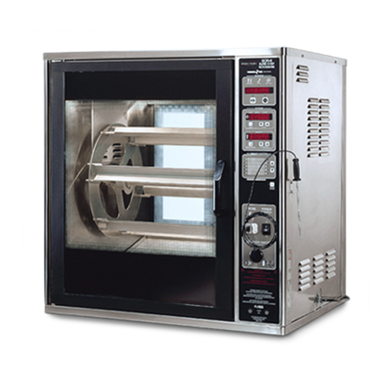
- Page 1 Henny Penny Rotisserie Model SCR-6/8 OPERATOR’S MANUAL...
- Page 3 0 TO 3 YEARS: During this time, any frypot that fails due to manufacturing or workmanship is- sues will be replaced at no charge for parts, labor, or freight. Henny Penny will either install a new frypot at no cost or provide a new or reconditioned replacement fryer at no cost.
-
Page 5: Table Of Contents
Section Section 1. INTRODUCTION ... 1-1 1-1. Henny Penny Rotisserie ... 1-1 1-2. Features ... 1-1 1-3. Assistance ... 1-1 1-4. Safety ... 1-2 1-5. Proper Care ... 1-2 Section 2. INSTALLATION ... 2-1 2-1. Introduction ... 2-1 2-2. Unpacking ... 2-1 2-3. -
Page 6: Section Page
Section Section 6. TROUBLESHOOTING ... 6-1 6-1. Troubleshooting Guide ... 6-1 6-2. Error Codes ... 6-2 GLOSSARY ... G-1 Distributors List - Domestic and International TABLE OF CONTENTS Page... -
Page 7: Section 1. Introduction
1-2. FEATURES 1-3. ASSISTANCE SECTION 1. INTRODUCTION The Henny Penny Rotisserie, SCR-6 or 8 , combines rotating convection heat with rotating discs so that food browns more evenly and cooks faster. It can also be used as a display unit for displaying product while in the cooking or holding mode. -
Page 8: Safety
1-4. SAFETY 1-5. PROPER CARE To ensure safe operation of the Henny Penny rotisserie, the proper procedures for installation, operation, and maintenance should be followed and properly understood. Where information is of particular importance or is safety related, the words WARNING, CAUTION, and NOTE are used. -
Page 9: Section 2. Installation
Any shipping damages should be noted in the presence of the delivery agent and signed prior to his or her departure. To remove the Henny Penny Rotisserie from the carton you should: Carefully cut banding straps. Remove packing from around the unit. -
Page 10: Location
The SCR-6/8 rotisseries must be 2 inches from any rear wall. No minimum spacing is required for the sides of the units. After the Henny Penny Rotisserie has been placed on a table, run a bead of silicone (silicone or equivalent sealant must be a NSF listed material) around the perimeter of the unit sealing it to the table top. - Page 11 2-4. STACKING INSTRUCTIONS (Continued) Figure 1 Figure 2 Take care when moving the unit to prevent personal injury. The SCR-8 weighs approximately 500 lbs. (230 kg) and the SCR-6 weighs 380 lbs. (172 kg). Remove the three side panel screws from the top unit and remove the three top side panel side screws from the bottom unit.
-
Page 12: Stacking Instructions For Single Power Cord Units
2-5. STACKING INSTRUCTIONS FOR SINGLE POWER CORD UNITS Figure 1 Figure 2 Figure 3 1. Lay unit on its side and bolt locking casters or legs, to the control side of unit. 2. Using the bolts provided for the non-locking casters, or legs, bolt both the stacking spacer (provided in the kit) and the non-locking caster, or legs, to the front side of the unit. -
Page 13: Stacking And Outboard Caster Installation Instructions
2-6. STACKING AND OUTBOARD CASTER INSTALLATION INSTRUCTIONS Figure 1 Figure 2 Figure 3 1. Using a Phillip’s head screwdriver, remove the 8, 1/4-20 x 1 in. screws in the corners of the unit. Figure 1. 2. Remove all contents from inside of unit. Carefully lay the unit over onto the customer side of the unit. - Page 14 2-6. STACKING AND OUTBOARD CASTER INSTALLATION INSTRUCTIONS (Continued) Figure 4 Figure 5 Figure 6 Attach casters to the caster bracket (Figure 4), mounting the two locking swivel casters to the control side of the unit and the non-locking casters to the customer side. Use the 5/16 inch hex head bolts, 5/16 inch locking washers, 5/16 inch nuts and 5/16 inch flat washers (use 2 flat washers per bolt;...
-
Page 15: Leveling Of Unit
For proper operation, the rotisserie should be level from side to side and front to back. This will ensure proper door operation. The Henny Penny Rotisserie is available from the factory, wired for 208 or 240 volt, 220-380 volt, 240-415 volt, 230-400 volt, 1 or 3 phase, 50/60 hertz service. -
Page 17: Section 3. Operation
Digital Displays Ready LED SECTION 3. OPERATION The Henny Penny Rotisserie is computer controlled. The computer control regulates the cabinet temperatures and provides timing and program functions of the rotisserie. This two position rocker switch controls power to the rotisserie... - Page 18 3-2. CONTROLS AND SWITCHES (Refer to Figures 3-1 and 3-2) (Continued) Item Description Start Button Stop Button Alarm Button Temperature Button Set Temperature Up and Down Buttons Set Time Up and Down Buttons Time LEDs Temperature LEDs Function Pressed to begin the unit preheating or begins a Cook Cycle Pressed to end a Cook or Hold Cycle Pressed to view or change the alarm settings;...
- Page 19 SCR-6/8 Figure 3-1...
- Page 20 Figure 3-2...
-
Page 21: Installation Of Discs, Rods, And Spits
3-3. INSTALLATION OF DISCS, RODS, AND SPITS Fit discs up to appropriate disc support on each side of unit. Place each end of the rod assembly into the hubs on each disc. Slide the collars onto each hub of discs. Slide retention rings over hubs and into slot on rod. -
Page 22: Procedure For Angled Spits
3-5. PROCEDURE FOR DOUBLE SPITS (OPTIONAL) Figure 3-4 The angled spits are the standard accessory for the Henny Penny rotisseries. Some of the advantages of the angled spits, compared to the double spits, are the ease and speed in which whole chickens can be placed on the spits. -
Page 23: Use Of Optional Accessories
Coated accessories are available. For more information, contact your local independent Henny Penny distributor. The control has ten product Cook Cycles which may be pro- grammed for specific products. Each cycle may consist of up to four cook steps and a hold parameter. -
Page 24: Preheat Control
3-7. OPERATION MODE (Continued) 3-8. PREHEAT CONTROL 3-9. COOKING CONTROL 3-10. DOOR SENSOR 3-11. HOLD CONTROL The middle display shows the time remaining and the bottom display shows the setpoint temperature. The actual tempera- ture shows when the oven temperature (thermometer) button is pressed. -
Page 25: Cleaning Procedures
3-12. CLEANING PROCEDURES Turn all controls to OFF and disconnect the electrical power supplied to the unit. To avoid severe burns, allow the unit to cool before cleaning. Remove the discs and rod assembly and take to a sink to clean them thoroughly. -
Page 26: Halogen Lamp Replacement
3-12. CLEANING PROCEDURES (Continued) 3-13. HALOGEN LAMP REPLACEMENT 3-10 Loosen the thumb screw on the blower fan blade and pull blade from shaft. Then take fan blade to a sink to clean thoroughly. When reinstalling fan blade, be sure the offset shaft matches up, and the thumb screw is tightened snug, but not too tight. -
Page 27: Section 4. Programming
4-1. INTRODUCTION 4-2. PROGRAMMING FOR COOK AND HOLD SECTION 4. PROGRAMMING The controls can be preset at the factory, or the desired functions can be programmed in the field. The program settings (P) button is used to program the following functions: cooking (steps), alarms, and hold. - Page 28 4-2. PROGRAMMING FOR COOK AND HOLD (Continued) The time can be programmed by pressing the UP and DOWN buttons under the time (middle) display. Example: “1:30:00” is 1 hour, 30 minutes, and 0 seconds. As many as four times and temperatures can be programmed per Cook Cycle.
- Page 29 4-2. PROGRAMMING FOR COOK AND HOLD (Continued) After multiple steps have been programmed, and the Program Mode exited, the total cook time will show in the display. The time for the next alarm can be viewed by pressing and holding the ALARM button. 10.
- Page 30 4-3. SPECIAL PROGRAM MODE (Level 2) The Special Program Mode is used to set more detailed parameters The Special Program Mode is accessed by pressing and holding the PROGRAM SETTINGS (P) button for 8 seconds, or until the display shows “L-2”. “LEVEL 2” flashes in the top display, then “SP PRG” shows in the display.
-
Page 31: Special Program Mode (Level 2)
4-3. SPECIAL PROGRAM MODE MODE (Level 2) (Continued) Audio Tone (SP-5) The tone of the speaker can be adjusted. After entering the access code (1,2,3), press the P button four times. “AUDIO TONE” shows in the top display, and a number 50 thru 2000 shows in the middle display. -
Page 32: Tech Mode
P button. The Tech Mode has many self diagnostic capabilities which are used for internal Henny Penny use only, and a different code is needed to access this mode. The word “TECH” shows in the display when the P button is pressed for eight seconds, and the P button pressed again, when “LEVEL 2”... -
Page 33: Section 5. Cooking Procedures
SECTION 5. COOKING PROCEDURES 5-1. PROGRAM COOK PARAMETERS 5-2. LOADING THE ROTISSERIE 5-3. REMOVING SPITS AND PRODUCT FROM THE ROTISSERIE Your rotisserie is preprogrammed at the factory for several types of products. The size, weight, temperature, and quantity of the product is critical to the success of the preset cooking programs. -
Page 34: Seasonings And Barbecue Sauce
5-5. BASIC RULES OF SAFE FOOD PREPARATION Henny Penny has two seasonings and a barbecue sauce available for use with the rotisserie. Lightly sprinkle or rub seasonings on meats evenly. Additional seasoning can be sprinkled in the cavity of whole poultry. -
Page 35: Minimum Temperature Requirements For Hot And Cold Food Storage
150 o F-165 o F (66 o C-74 o C), depending upon local health regulations, before serving or placing in hot food storage. Here too, Henny Penny has several sizes of blast chillers to help cool product down to a safe temperature. -
Page 36: Basic Cooking Procedures
5-8. BASIC COOKING PROCEDURES 1. Choose the desired product by pressing the UP or DOWN button, then press the START button to begin preheating. Season product and load onto spits. Once READY LED is lit, use the MANUAL ROTATION switch to load product into rotisserie. Press the START button again to start the Cook Cycle. -
Page 37: Cooking Guidelines
5-9. COOKING GUIDELINES Whole Chicken, Fresh-3 Pounds Each Remove excess fat and skin from thigh and neck area. Rinse birds inside and out with cool tap water. Marinate if desired. Tuck wings and tuck or tie legs. Place on spits, or in baskets, and season as desired. - Page 38 5-9. COOKING GUIDELINES (Continued) Chicken Quarters, Fresh-2 ½-2¾ Pounds Marinate and season as desired. Place chicken quarters in baskets, bone down. SCR-8 Chicken Quarters Per Basket Cook Times SCR-6 0:50:00-0:55:00 Whole Turkey, Fresh-10 - 12 Pounds Clean turkeys and remove the necks and gizzards. Marinate and season as desired.
- Page 39 5-9. COOKING GUIDELINES (Continued) Spare Ribs, Canadian Style-2 - 2½ Pounds Remove excess fat from the ribs and rinse with cool tap water. Weave ribs into the piercing spit. Season as desired. SCR-8 Number of Ribs Cook Times 1:50:00 SCR-6 2:00:00 Preheat/Cook Temp.
-
Page 40: Section 6. Troubleshooting
SECTION 6. TROUBLESHOOTING 6-1. TROUBLESHOOTING GUIDE PROBLEM Product color too dark Product color too light Dry product Meat separation from bone With power switch in POWER position the rotisserie is completely inoperative. Unit will not heat CAUSE • Temperature too high •... -
Page 41: Error Codes
6-2. ERROR CODES DISPLAY “E-4” • Control board too hot; “Prob Err” “E-6” • Temperature probe “ctrl hot” “E-50” “CPU Chip” • CPU RAM Error “E-51” “rA-CHIP” •External RAM error “E-53” “ro-CHIP” • External ROM error “E-41” “data Err” • Scrambled Memory “E-5”... -
Page 42: Glossary
air heat air heating elements baskets double spits drain pan black plug button channel assembly collar disc disc assembly disc supports drip trays meat probe receptacle radiant heat radiant heating elements G L O S S A R Y SCR & SCD GLOSSARY heat inside the unit created by air blowing across heaters in the top of the unit heaters in the top of the unit that heats the air blowing across them... - Page 43 retention ring rod assembly rotation switch rotor motor setpoint side racks spits stacking kit stacking spacer vent panels part of the rod assembly that fits in a groove behind the collar to hold the discs in place the device that spans between the discs that includes the rod, collars, and retention rings the large, black button when pushed, rotates the discs to position the product for loading, removing, or seasoning...
- Page 44 Henny Penny Corporation P.O.Box 60 Eaton,OH 45320 1-937-456-8400 1-937-456-8402 Fax Toll free in USA 1-800-417-8417 1-800-417-8434 Fax *FM05-014-D* www.hennypenny.com Henny Penny Corp., Eaton, Ohio 45320, Revised 4-19-06...