Henny Penny SCR-6 Technical Manual
Hide thumbs
Also See for SCR-6:
- Operator's manual (44 pages) ,
- Brochure (12 pages) ,
- Service manual (70 pages)
Table of Contents
Advertisement
Quick Links
Advertisement
Table of Contents
Troubleshooting

Related Manuals for Henny Penny SCR-6


Summary of Contents for Henny Penny SCR-6
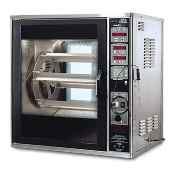
- Page 1 Henny Penny Rotisserie Model SCR-6/8 TECHNICAL MANUAL...
-
Page 3: Table Of Contents
SCR-6/8 TABLE OF CONTENTS Section Page Section 1. TROUBLESHOOTING ................... 1-1 1-1. Introduction ....................1-1 1-2. Safety ......................1-1 1-3. Troubleshooting ....................1-1 1-4. Error Codes ....................1-3 Section 2. MAINTENANCE ..................... 2-1 2-1. Introduction ....................2-1 2-2. Maintenance Hints ..................2-1 2-3. -
Page 5: Troubleshooting
SCR-6/8 SECTION 1. TROUBLESHOOTING This section provides troubleshooting information in the 1-1. INTRODUCTION form of an easy to read table. If a problem occurs during the first operation of a new rotisserie, recheck the installation per the Installation Section of the Operator’s Manual. -
Page 6: Troubleshooting
SCR-6/8 1-3. TROUBLESHOOTING (Continued) Problem Cause Correction COOKING SECTION Product Color Not Correct: • • A. Too Dark Temperature too high Check probe position; see Thermal Sensor Replacement Section • Check temperature setting in the program mode; see Programming Section in Operator’s Manual •... -
Page 7: Error Codes
SCR-6/8 1-3. TROUBLESHOOTING (Continued) Problem Cause Correction • • Product not done Low or improper voltage Use a meter and check the receptacle against data plate • • Weak or burnt out elements Check heating element(s) per Radiant Heaters Section •... - Page 8 SCR-6/8 THIS PAGE INTENTIONALLY LEFT BLANK.
-
Page 9: Section 2. Maintenance
SCR-6/8 SECTION 2. MAINTENANCE This section provides procedures for the checkout and replacement of 2-1. INTRODUCTION the various parts used within the rotisserie. Before replacing any parts, refer to the Troubleshooting Section. It will aid you in determining the cause of the malfunction. -
Page 10: Blower Replacement
SCR-6/8 Remove electrical power to unit. 2-4. BLOWER REPLACEMENT To avoid electrical shock or property damage, move the power switch to OFF and disconnect main circuit breaker, or unplug cord at wall receptacle. Using Phillips head screwdriver , remove the side panel closest to the controls. -
Page 11: Thermal Sensor Replacement
SCR-6/8 2-5. THERMAL SENSOR REPLACEMENT Remove electrical power to unit. To avoid electrical shock or property damage, move the power switch to OFF and disconnect main circuit breaker, or unplug cord at wall receptacle. Remove the side panel closest to the controls. -
Page 12: Contactor
SCR-6/8 1. Remove electrical power to unit. 2-6. CONTACTOR To avoid electrical shock or property damage, move the power switch to OFF and disconnect main circuit breaker, or unplug cord at wall receptacle. Checkout: 2. Remove the side panel closest to the controls. -
Page 13: Drive Motor Replacement Kit
SCR-6/8 2-6. CONTACTOR (Continued) 6. Check voltage as follows: Test Points Results from terminal 29 to 28 The voltage from terminal 27 to 28 should read the from terminal 27 to 29 same at each terminal. Replacement: If contactor proves defective: 7. -
Page 14: Rotation Control Switch
SCR-6/8 6. Slide extension hub (on motor) into slot on the unit, and 2-7. DRIVE MOTOR bolt the motor to the bracket. Snug, but don’t tighten nuts. REPLACEMENT KIT (Continued) 7. Install discs into unit and place rod into place. - Page 15 SCR-6/8 Remove screws securing the side panel closest to the 2-8. ROTATION CONTROL controls. SWITCH (Continued) Remove and label wires from terminals of switch. Take a continuity reading across terminals. If meter shows constant open or closed circuit each time the button is pushed, the switch is defective.
-
Page 16: Capacitor Replacement - Blower Motor
SCR-6/8 2-9. CAPACITOR REPLACE- MENT - BLOWER MOTOR 1. Remove electrical power supplied to unit. To avoid electrical shock or property damage, move the power switch to OFF and disconnect main circuit breaker, or unplug cord at wall receptacle. Remove the side panel closest to the controls. -
Page 17: Door Sensor Replacement
SCR-6/8 1. Remove electrical power supplied to unit. 2-11. DOOR SENSOR REPLACEMENT To avoid electrical shock or property damage, move the power switch to OFF and disconnect main circuit breaker, or unplug cord at wall receptacle. 2. Remove appropriate side panel. -
Page 18: Socket - Halogen Lamp
SCR-6/8 1. Remove electrical power supplied to unit. 2-12. SOCKET - HALOGEN LAMP To avoid electrical shock or property damage, move the power switch to OFF and disconnect main circuit breaker, or unplug cord at wall receptacle. 2. Remove appropriate side panel. -
Page 19: Radiant Heaters
SCR-6/8 1. Remove electrical power to unit. 2-14. RADIANT HEATERS To avoid electrical shock or property damage, move the power switch to OFF and disconnect main circuit breaker, or unplug cord at wall receptacle. 2. If removing air heaters, remove top vent panel. (See Step 2 Cleaning Section of Operator’s Manual.) -
Page 20: Control Board Speaker Replacement
SCR-6/8 1. Remove electrical power supplied to the unit. 2-15. CONTROL BOARD SPEAKER REPLACEMENT To avoid electrical shock or property damage, move the power switch to OFF and disconnect main circuit breaker, or unplug cord at wall receptacle. 2. Remove the side panel closest to the controls. -
Page 21: Control Board Replacement
SCR-6/8 1. Remove electrical power supplied to the unit. 2-17. CONTROL BOARD REPLACEMENT To avoid electrical shock or property damage, move the power switch to OFF and disconnect main circuit breaker, or unplug cord at wall receptacle. 2. Remove the Phillips head screws securing the side Step 3 panel closest to the controls and then remove side panel. - Page 22 SCR-6/8 2-13 2-18. RELAYS (Continued) To avoid electrical shock, make connections before applying power, take reading, and remove power before removing meter leads. The following checks are performed with the wall circuit breaker closed and the main power switch in the ON position.
-
Page 23: High Limit
Once the temperature inside the unit goes down, then the high limit automatically resets and the unit can then be heated. All SCRs have two high limits. The SCR-6 and SCR-8 both have a 450ºF high limit and a 500ºF high limit. The SCR-3 has a 285ºF high limit and a 450ºF high limit. - Page 24 SCR-6/8 2-19. HIGH LIMIT (Continued) Units with a small diameter hole, in the high limit box, must follow the preceding steps to access the wires and mounting nuts of the high limit. Units with a large diameter hole can access the wires and mounting nuts from the hole in the front of the box.
-
Page 25: Wiring Diagrams
SCR-6/8 2-20. WIRING DIAGRAMS (SN: CA0405008 & below) 2-17... - Page 26 SCR-6/8 2-20. WIRING DIAGRAMS (Continued) SN: CA0610018 & Below - SCR-6 SN: CB0610032 & Below - SCR-8 2-18...
- Page 27 SCR-6/8 SN: CA0610019 & Above - SCR-6 SN: CB0610033 & Above - SCR-8 2-19...
- Page 28 SCR-6/8 2-20. WIRING DIAGRAMS (Continued) SN: CA0610018 & Below - SCR-6 SN: CB0610032 & Below - SCR-8 2-20...
- Page 29 SCR-6/8 SN: CA0610019 & Above - SCR-6 SN: CB0610033 & Above - SCR-8 2-21...
- Page 30 SCR-6/8 2-22 1204...
- Page 31 SCR-6/8 International wiring diagram SN: CA0610018 & Below - SCR-6 SN: CB0610032 & Below - SCR-8 2-23...
- Page 32 SCR-6/8 International wiring diagram SN: CA0610019 & Above - SCR-6 SN: CB0610033 & Above - SCR-8 2-24...
- Page 33 SCR-6/8 SN: CA0610018 & Below - SCR-6 SN: CB0610032 & Below - SCR-8 2-25...
- Page 34 SCR-6/8 SN: CA0610019 & Above - SCR-6 SN: CB0610033 & Above - SCR-8 2-26...
- Page 35 During this time, any frypot that fails due to manufacturing or workmanship issues will be replaced at no char g e for parts, labor , or freight. Henny Penny will either install a new frypot at no cost or provide a new or reconditioned replacement fryer at no cost.
-
Page 37: Section 3. Parts Information
This section identifies and lists the replaceable parts of the 3-1. INTRODUCTION Henny Penny SCR Rotisserie. Use only genuine Henny Penny parts in your cabinet. Using a 3-2. GENUINE PARTS part of lesser quality or substitute design may result in cabinet damage or personal injury . - Page 38 40926 DISC - FINISH - SCR-8 49184 DISC - COATED - SCR-8 43683 DISC - FINISH - KFC - SCR-6 41350 LH DISC ASSY - COMPLETE - SCR-8 49182 LH DISC ASSY-COATED - COMPLETE - SCR-8 (Walmart use 12/20/10 & after)
- Page 39 49185 WELDMENT - DRIVE TUBE - SCR-8 - COA TED 40826 WELDMENT - DRIVE TUBE - SCR-6 49192 WELDMENT - DRIVE TUBE - SCR-6 - COA TED 40242 HUB - DRIVE SIDE 49187 HUB - DRIVE SIDE - COA TED...
- Page 40 RADIANT HEA TER-230V 2000W SC02-041 SCREW 67983 HEATER BRACKET SC02-041 SCREW SC02-041 SCREW 21657 LAMP GUARD - SCR-6 21658 LAMP GUARD - SCR-8 14241 KIT-SCR-8 DEFLECTOR-RADIANT HTR 14725 KIT-SCR-6 DEFLECTOR-RADIANT HTR √ √ √ √ √ recommended parts/*not shown 1210...
- Page 41 SCR-6/8 Figure 3-3. Ducts ITEM PART QTY. QTY. DESCRIPTION SCR-8 SCR-6 40577 REMOVABLE DUCT-L.H 49179 REMOVABLE DUCT-L.H. COATED 40707 REMOVABLE DUCT-L.H 49189 REMOVABLE DUCT-L.H COATED 40049 TOP REMOVABLE DUCT 40581 TOP REMOVABLE DUCT 63890 INSULATION, TOP AIR DUCT 40309 REMOVABLE DUCT-BLOWER-SCR8 43517 REMOVABLE DUCT-BLOWER-SCR6-SN: CA0601003 &...
- Page 42 SCR-6/8 Figure 3-4. Controls and Doors 1210...
- Page 43 DOOR ASSY-MIRRORED-CONTROL SIDE W/ HANDLE - 49263 DOOR ASSY . CUST. SIDE W/O HANDLE 49264 DOOR ASSY . CUST. SIDE W/ HANDLE 24170 DOOR ASSY. CURVED GLASS - SCR-6 SC01-074 SCREW 48549 HINGE - CONTROL SIDE 48567 HINGE - CUSTOMER SIDE...
- Page 44 SCR-6/8 Figure 3-5. SCR-8 Short and Tall Units Special Parts QTY. ITEM NO. PART NO. DESCRIPTION SCR-8 59745 DOOR ASSY-CNTRL. SIDE W/ HNDL-SHORT (SN: JE049JJ & UP) 59784 DOOR ASSY-MIR.CNTRL SIDE W/ HNDL-SHORT (SN: JE049JJ & UP) 1 59772 DOOR ASSY, CUST SIDE W/O HNDL-SHORT (SN: JE049JJ & UP) 59785 DOOR ASSY, CUST SIDE W/ HNDL-SHORT (SN: JE049JJ &...
- Page 45 SCR-6/8 Figure 3-6. Drive Motor QTY. QTY. ITEM NO. PART NO. DESCRIPTION SCR-8 SCR-6 √ √ √ √ √ 1 14242 DRIVE MOTOR ASSY. (INCLUDES 56164) √ √ √ √ √ 2 56164 CAPACITOR, DRIVE MOTOR-4MF SC01-053 SCREW NS02-007 SC01-185...
- Page 46 SCR-6/8 Figure 3-7. Electrical Components 3-10...
- Page 47 SCR-6/8 FIGURE & QTY. QTY. ITEM NO. PART NO. DESCRIPTION SCR-8 SCR-6 ELECTRICAL COMPONENTS SC04-017 SCREW 63727 TERMINAL BLOCK ASSY. - 1 PHASE 52994 TERMINAL BLOCK ASSY. - 3 PHASE 52995 TERMINAL BLOCK - CE 40645 S.S. RELAY √ √ √ √ √...
- Page 48 SCR-6/8 Figure 3-8. High Limit Switches and Blower 3-12...
- Page 49 SCR-6/8 FIGURE & QTY. QTY. ITEM NO. PART NO. DESCRIPTION SCR-8 SCR-6 HIGH LIMIT SWITCHES AND BLOWER SC02-016 SCREW √ √ √ √ √ 2 51476 SPEAKER ASSY . ME50-033 SPACER NS02-009 √ √ √ √ √ 5 TS13-001 40 WATT SWITCHING PWR. SUPPL Y...
- Page 50 POWER CORD ASSY.-GM-OUTBOARD - TOP 63714-03 POWER CORD ASSY.-GM-OUTBOARD - BOT 40998 POWER CORD ASSY. - 30 AMP - SCR-6 (3 PH) 88843 ASSY-POWER CORD 30 AMP 90° PLUG 41659 POWER CORD ASSY. - 50 AMP - SCR-6 (1 PH) 63714-04 PWR CORD ASSY-90°...
- Page 51 TRAYS, PANS, AND POWER CORDS (CONTD.) 54671 POWER CORD ASSY- 90° PLUG (ALBRTSN) 16242 PLUG MO-500 NEMA 15-50P - SCR-8 40884 PLUG 30A - 250V - NEMA 15-30P - SCR-6 88809 PLUG-250V/NEMA 15-30P 90° 58146 PLUG 60A- 3PH 250V-NEMA15-60P 90°(ALBERTSON) 21335 PLUG 50A- 3PH 250V 90°(ALBERTSONS)