
Related Manuals for Supero SC219 Chassis Series


Summary of Contents for Supero SC219 Chassis Series
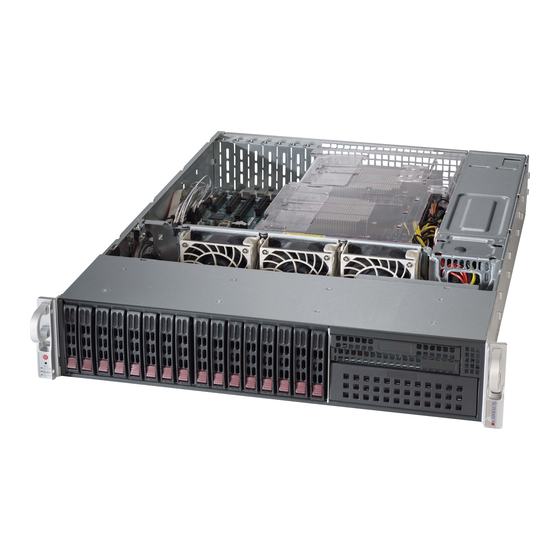
- Page 1 UPER ® SC219 Chassis Series SC219A-R920UB SC219A-R920LPB SC219A-R920WB USER’S MANUAL...
- Page 2 SC219 Chassis Manual The information in this User’s Manual has been carefully reviewed and is believed to be accurate. The vendor assumes no responsibility for any inaccuracies that may be contained in this document, makes no commitment to update or to keep current the information in this manual, or to notify any person or organization of the updates.
- Page 3 Preface Preface This manual is written for professional system integrators and PC technicians. It provides information for the installation and use of the SC219 chassis. Installation and maintenance should be performed by experienced technicians only. Supermicro’s SC219 chassis features a unique and highly optimized 2U server design which provides optimal use of space, without compromising cooling.
-
Page 4: Manual Organization
SC219 Chassis Manual Manual Organization Chapter 1 Introduction The introduction provides a list of the main components included with this chassis and describes the primary features of the SC219 chassis. This chapter also includes contact information. Chapter 2 System Safety Chapter 2 lists warnings, precautions, and system safety. - Page 5 Preface Appendix C This section provides detailed information on the SAS-213A backplane. Additional information can by found on our Web site, at www.supermicro.com...
-
Page 6: Table Of Contents
SC219 Chassis Manual Table of Contents Manual Organization ..................iv Chapter 1 Introduction Overview ......................1-1 Shipping List ....................1-1 Contacting Supermicro ..................1-2 Returning Merchandise for Service..............1-3 Chapter 2 System Safety Overview ......................2-1 Warnings and Precautions ................2-1 Preparing for Setup .................. - Page 7 Preface 4-13 Power Distributor ................... 4-16 4-14 Removing the Backplane ................4-17 4-15 Installing the Backplane ................4-19 Chapter 5 Rack Installation Overview ......................5-1 Unpacking the System ..................5-1 Preparing for Setup ..................5-1 Choosing a Setup Location ................5-1 Warnings and Precautions ................
- Page 8 SC219 Chassis Manual Notes viii...
-
Page 9: Chapter 1 Introduction
Chapter 1 Introduction Chapter 1 Introduction Overview Supermicro’s SC219 chassis provides sixteen hot-swappable 2.5” SAS/SATA hard drive bays, one 5.25” hard drive and two peripheral drive bays in an efficient 2U form factor, designed for the most frequently encountered applications. The chassis is also equipped with a redundant 920W Platinum Level (94%+) power supply for superb power savings and optimized cooling. -
Page 10: Contacting Supermicro
SC219 Chassis Manual Contacting Supermicro Headquarters Address: Super Micro Computer, Inc. 980 Rock Ave. San Jose, CA 95131 U.S.A. Tel: +1 (408) 503-8000 Fax: +1 (408) 503-8008 Email: marketing@supermicro.com (General Information) support@supermicro.com (Technical Support) Web Site: www.supermicro.com Europe Address: Super Micro Computer B.V. Het Sterrenbeeld 28, 5215 ML 's-Hertogenbosch, The Netherlands Tel:... -
Page 11: Returning Merchandise For Service
Chapter 1: Introduction Returning Merchandise for Service A receipt or copy of your invoice marked with the date of purchase is required be- fore any warranty service will be rendered. You can obtain service by calling your vendor for a Returned Merchandise Authorization (RMA) number. When returning to the manufacturer, the RMA number should be prominently displayed on the outside of the shipping carton, and mailed prepaid or hand-carried. - Page 12 SC219 Chassis Manual Notes...
-
Page 13: Chapter 2 System Safety
Chapter 2: System Safety Chapter 2 System Safety Overview This chapter lists warnings, precautions, and system safety. You should thoroughly familiarize yourself with this chapter for a general overview of safety precautions that should be followed before installing and servicing this chassis. Warnings and Precautions You should inspect the box the chassis was shipped in and note if it was damaged in any way. -
Page 14: Electrical Safety Precautions
SC219 Chassis Manual Electrical Safety Precautions Basic electrical safety precautions should be followed to protect yourself from harm and the SC219 from damage: • Be aware of the locations of the power on/off switch on the chassis as well as the room’s emergency power-off switch, disconnection switch or electrical outlet. -
Page 15: General Safety Precautions
Chapter 2: System Safety • Please handle used batteries carefully. Do not damage the battery in any way; a damaged battery may release hazardous materials into the environment. Do not discard a used battery in the garbage or a public landfill. Please comply with the regulations set up by your local hazardous waste management agency to dispose of your used battery properly. - Page 16 SC219 Chassis Manual • Use a grounded wrist strap designed to prevent static discharge. • Keep all components and printed circuit boards (PCBs) in their antistatic bags until ready for use. • Touch a grounded metal object before removing any board from its antistatic bag.
-
Page 17: Chapter 3 System Interface
Chapter 3: System Interface Chapter 3 System Interface Overview There are LEDs on the left control panel and LEDs on the drive carriers to keep you constantly informed of the over-all status of the system, as well as the activity and health of specific components. -
Page 18: Control Panel Buttons
SC219 Chassis Manual Control Panel Buttons There are two push-buttons located on the control panel on the left side of the chassis. These are a power on/off button and a reset button. Power: The main power switch is used to apply or remove power from the power supply to the server system. - Page 19 Chapter 3: System Interface NIC1: Indicates network activity on GLAN1 when flashing. NIC2: Indicates network activity on GLAN2 when flashing. Power Failure: When this LED flashes, it indicates a power failure in the power supply. Informational LED Status Description An overheat condition has occured. Continuously on and red (This may be caused by cable congestion.) Blinking red (1Hz)
-
Page 20: Drive Carrier Leds
SC219 Chassis Manual Drive Carrier LEDs Your chassis uses SAS/SATA drives. SAS/SATA Drives Each SAS/SATA drive carrier has two LEDs. Green LED: Each SAS/SATA drive carrier has a green LED. When illuminated, this green LED (on the front of the SATA drive carrier) indicates drive activity. A connection to the SATA backplane enables this LED to blink on and off when that particular drive is being accessed. -
Page 21: Chapter 4 Chassis Setup And Maintenance
Chapter 4: Chassis Setup and Maintenance Chapter 4 Chassis Setup and Maintenance Overview This chapter covers the steps required to install components and perform mainte- nance on the SC219 chassis. The only tool you will need to install components and to perform maintenance is a Phillips screwdriver. -
Page 22: Removing The Chassis Cover
SC219 Chassis Manual Removing the Chassis Cover Figure 4-1: Removing the Chassis Cover Removing the Chassis Cover the Chassis Cover 1. Disconnect the chassis from any power source. 2. Press both release tabs at the same time to release the cover from the locked position. -
Page 23: Installing Hard Drives
Chapter 4: Chassis Setup and Maintenance Installing Hard Drives Figure 4-2: Removing the Hard Drive Carrier The SC219 comes equipped with sixteen hot-swappable hard drives. Only SAS or enterprise SATA HDDs are recommended for use in the SC219 chassis. Hot-swappable drives may be installed and removed from the chassis without powering down the server. - Page 24 SC219 Chassis Manual Figure 4-3: Installing a Hard Drive in the Drive Carrier Installing a Hard Drive into a Drive Carrier 1. Remove the screws securing the dummy drive to the drive carrier. 2. Insert a drive into the carrier with the PCB side facing down and the connec- tor end toward the rear of the carrier and align the drive in the carrier so that the mounting holes of the carrier are aligned with the mounting holes of the drive.
-
Page 25: Installing The I/O Shield (Lp Version Only)
Chapter 4: Chassis Setup and Maintenance Installing the I/O Shield (LP Version Only) I/O Shield Figure 4-5: I/O Shield Placement I/O Shield (LP Version Only) Skip this section when using a UIO/WIO chassis with a UIO/WIO motherboard. The I/O shield holds the motherboard ports in place. Install the I/O shield before installing the motherboard. -
Page 26: Installing Chassis Standoffs
SC219 Chassis Manual Installing Chassis Standoffs Chassis Standoffs Figure 4-6: Chassis Standoffs Permanent and Optional Standoffs Standoffs prevent short circuits by creating space between the motherboard and the chassis surface. The SC219 chassis includes permanent standoffs in locations used by most motherboards. These standoffs accept the rounded Phillips head screws which are included in the SC219 accessories packaging. -
Page 27: Installing The Motherboard
Chapter 4: Chassis Setup and Maintenance Installing the Motherboard Installing the Motherboard 1. Review the documentation that came with your motherboard. Become familiar with component placement, requirements, cautions, and cable connections. Note that your motherboard may be different than those illustrated. 2. - Page 28 SC219 Chassis Manual 7. Secure the CPU(s), heatsinks, and other components to the motherboard as described in the motherboard documentation. 8. Connect the cables between the motherboard, backplane, chassis, front panel, and power supply, as needed. Additionally, the fans may be temporar- Figure 4-8: Motherboard Installed in a UIO/WIO Model Chassis...
-
Page 29: Installing The Riser And Expansion Cards
Chapter 4: Chassis Setup and Maintenance Installing the Riser and Expansion Cards The SC219 chassis supports four full-length half-height expansion cards and two low-profile expansion cards. Installing Riser Cards and Full-Length Expansion Cards 1. Remove the chassis from any power source and ensure that the motherboard has been properly installed. - Page 30 SC219 Chassis Manual 4. Insert the full-length expansion card into the riser card. 5. Slide the riser card carefully into the PCI/PCIE slot and simultaneously plug it into the slot on the motherboard. 6. Use two screws to secure the head of the riser card bracket onto the chassis wall and one screw to secure the riser card bracket to the floor fo the chassis.
-
Page 31: Installing The Air Shroud
Chapter 4: Chassis Setup and Maintenance Installing the Air Shroud Figure 4-11: Air Shroud Installation Air shrouds concentrate airflow to maximize fan efficiency. The SC219 chassis air shroud does not require screws for installation. Installing the Air Shroud in the Chassis Installing the Air Shroud 1. -
Page 32: 4-10 Checking The Airflow
SC219 Chassis Manual 4-10 Checking the Airflow Checking the Server's Airflow 1. Make sure there are no objects to obstruct airflow in and out of the server. In addition, if you are using a front bezel, make sure the bezel's filter is replaced periodically. -
Page 33: 4-11 System Fans
Chapter 4: Chassis Setup and Maintenance 4-11 System Fans Up to seven heavy-duty fans may be used to provide cooling for the chassis. Four fans are located on the front side of the fan bracket, and three optional fans may be placed on the rear side of the fan bracket for cooling redundancy with E-ATX or ATX motherboards. - Page 34 SC219 Chassis Manual Figure 4-13: Installing a Front System Fan Figure 4-14: Installing an Optional System Fan 4-14...
-
Page 35: 4-12 Power Supply
Chapter 4: Chassis Setup and Maintenance 4-12 Power Supply The SC219 chassis has redundant 920 Watt power supplies. The power modules are hot-swappable, enabling them be changed without powering down the system. These power supplies are auto-switching capable. This enables the power supply to automatically sense and operate at a 100v to 240v input voltage. -
Page 36: 4-13 Power Distributor
SC219 Chassis Manual Figure 4-16 Installing the Power Distributor 4-13 Power Distributor The power distributor provides failover and power supply redundancy and is pre- installed in the chassis. In the unlikely event that you have to replace the power distributor, follow the steps below. Changing the Power Distributor 1. -
Page 37: 4-14 Removing The Backplane
Chapter 4: Chassis Setup and Maintenance 4-14 Removing the Backplane The SC219 chassis backplane is located behind the hard drives and in front of the front system fans. In order to change jumper settings on the backplane, it may be necessary to remove the backplane from the chassis. - Page 38 SC219 Chassis Manual 6. Loosen but do not remove the three screws in the spring bar, located on the floor of the chassis, indicated by the arrows below. Figure 4-18: Loosening the Spring Bar Screws in the Floor of the Chassis 7.
-
Page 39: 4-15 Installing The Backplane
Chapter 4: Chassis Setup and Maintenance 4-15 Installing the Backplane Installing the Backplane into the Chassis 1. Ensure that all of the hard drive carriers have been removed from the bays in the front of the chassis and that the spring bar has been loosened as directed in the previous section. - Page 40 SC219 Chassis Manual Notes 4-20...
-
Page 41: Chapter 5 Rack Installation
Chapter 5: Rack Installation Chapter 5 Rack Installation Overview This chapter provides instructions for installing the mounting rails onto a rack and installing the chassis into the mounting rails. Unpacking the System You should inspect the box which the chassis was shipped in and note if it was damaged in any way. -
Page 42: Warnings And Precautions
SC219 Chassis Manual Warning! Warnings and Precautions Rack Precautions • Ensure that the leveling jacks on the bottom of the rack are fully extended to the floor with the full weight of the rack resting on them. • In single rack installations, stabilizers should be attached to the rack. •... -
Page 43: Rack Mounting Considerations
Chapter 5: Rack Installation • Always keep the rack's front door and all panels and components on the servers closed when not servicing to maintain proper cooling. Rack Mounting Considerations Ambient Operating Temperature If installed in a closed or multi-unit rack assembly, the ambient operating tempera- ture of the rack environment may be greater than the ambient temperature of the room. -
Page 44: Rack Mounting Instructions
SC219 Chassis Manual Rack Mounting Instructions This section provides information on installing the chassis into a rack unit with the rails provided. There are a variety of rack units on the market, which may mean that the assembly procedure will differ slightly from the instructions provided. You should also refer to the installation instructions that came with the rack unit you are using. -
Page 45: Locking Tabs
Chapter 5: Rack Installation Locking Tabs Each inner rail has a locking tab. This tab locks the chassis into place when installed and pushed fully into the rack. These tabs also lock the chassis in place when fully extended from the rack. This prevents the server from coming completely out of the rack when when the chassis is pulled out for servicing. -
Page 46: Installing The Inner Rails On The Chassis
SC219 Chassis Manual Inner Rails Figure 5-3: Installing the Inner Rails Figure 5-4: Inner Rails Installed on the Chassis Installing The Inner Rails on the Chassis Installing the Inner Rails 1. Confirm that the left and right inner rails have been correctly identified. Place the inner rail firmly against the side of the chassis, aligning the hooks on the side of the chassis with the holes in the inner rail. -
Page 47: Installing The Outer Rails On The Rack
Chapter 5: Rack Installation L-min=676.00(26.61")(outer rail) 21D01 Figure 5-5: Extending and Releasing the Outer Rails Installing the Outer Rails on the Rack Installing the Outer Rails 1. Press upward on the locking tab at the rear end of the middle rail. 2. -
Page 48: Standard Chassis Installation
SC219 Chassis Manual Ball-Bearing Shuttle Figure 5-6: Installing into a Rack Standard Chassis Installation Installing the Chassis into a Rack 1. Confirm that the inner rails are properly installed on the chassis. 2. Confirm that the outer rails are correctly installed on the rack. 3. -
Page 49: Optional Quick Installation Method
Chapter 5: Rack Installation Optional Quick Installation Method The following quick installation method may be used to install the chassis onto a rack. Installing the Chassis into a Rack 1. Install the whole rail assembly onto the rack as described on page 5-7. 2. - Page 50 SC219 Chassis Manual Notes 5-10...
-
Page 51: Appendix A Sc219 Chassis Cables
Appendix A: Chassis Cables Appendix A SC219 Chassis Cables A-1 Overview This appendix lists supported cables for your chassis system. It only includes the most commonly used components and configurations. For more compatible cables, refer to the manufacturer of the motherboard you are using and our Web site at: www.supermicro.com. - Page 52 SC219 Chassis Manual A-3 Compatible Cables These cables are compatible with the SC219 Chassis. Alternate SAS/SATA Cables Some compatible motherboards have different connectors. If your motherboard has only one SAS connector that the SAS/SATA cables must share, use one of the following cables.
- Page 53 Appendix A: Chassis Cables Extending Power Cables Although Supermicro chassis are designed to be efficient and cost-effective, some compatible motherboards have power connectors located in different areas. To use these motherboards you may have to extend the power cables to the moth- erboards.
- Page 54 SC219 Chassis Manual Notes...
-
Page 55: Appendix B Sc219 Power Supply Specifications
Appendix B: Power Supply Specifications Appendix B SC219 Power Supply Specifications This appendix lists power supply specifications for the SC219 system. SC219A-R920LPB, SC219A-R920UB, SC219A-R920WB 920W MFR Part # PWS-920P-1R 100 - 240V AC Input 50 - 60Hz 11 - 4.5 Amp 4 Amp @ +5V standby DC Output 75 Amp @ +12V +5V: 50 Amp... - Page 56 SC219 Chassis Manual Notes...
-
Page 57: Appendix C Sas-213A Backplane Specifications
Appendix C: SAS-213A Backplane Specifications Appendix C SAS-213A Backplane Specifications To avoid personal injury and property damage, carefully follow all the safety steps listed below when accessing your system or handling the components. C-1 ESD Safety Guidelines Electrostatic Discharge (ESD) can damage electronic com ponents. To prevent dam- age to your system, it is important to handle it very carefully. - Page 58 SC219 Chassis Manual C-3 A Note to Users • All images and layouts shown in this user's guide are based upon the latest PCB Revision available at the time of publishing. The card you have received may or may not look exactly the same as the graphics shown in this manual. C-4 Introduction to the SAS-213A Backplane The SAS-213A backplane has been designed to utilize the most up-to-date technol- ogy available, providing your system with reliable, high-quality performance.
- Page 59 Appendix C: SAS-213A Backplane Specifications C-5 Front Connectors and Jumpers JP35 SAS IN#4 SAS IN#3 SAS IN#2 JSM3 JSM2 9072#1 RST JSM4 1-2:RST JP69: UPGRADE#1 BAR CODE 2-3:NO RST C133 SAS IN#1 JP96 JP52 JP95 R125 R392 JP37 I2C#4 I2C#3 I2C#2 R624 I2C#1...
- Page 60 SC219 Chassis Manual C-6 Front Connector and Pin Definitions 1. Upgrade Connectors The upgrade connectors are designated JP69, and JP78 are used for manufacturer's diagnos- tic purposes only. 2. - 5. I C Connectors C Connector Pin Definitions The I C Connectors, designated JP37, JP95, Pin# Definition JP52 and JP96 are used to monitor HDD ac- Data...
- Page 61 Appendix C: SAS-213A Backplane Specifications 11. - 12. ACT_IN: SAS Activity LED Header Pin Definitions The activity LED connectors, designated JP26, Pin# Definition Pin# Definition and JP27 are used to indicate the activity ACT IN#0 ACT IN#4 status of each SAS drive. The activity LED ACT IN#1 ACT IN#5 connector is located on the front panel.
- Page 62 SC219 Chassis Manual C-7 Front Jumper Locations and Pin Definitions JP35 SAS IN#4 SAS IN#3 SAS IN#2 JSM3 JSM2 9072#1 RST JSM4 1-2:RST BAR CODE JP69: UPGRADE#1 2-3:NO RST C133 JP96 SAS IN#1 JP52 JP95 R125 R392 JP37 I2C#4 I2C#3 R624 I2C#2 JSM1 I2C#1 R123 C132 R124...
- Page 63 Appendix C: SAS-213A Backplane Specifications C and SGPIO Modes and Jumper Settings This backplane can utilize I C or SGPIO. SGPIO is the default mode and can be used without making changes to your jumper. The following information details which jumper must be configured to use SGPIO mode or restore your backplane to I C mode.
-
Page 64: Front Panel Leds
SC219 Chassis Manual JP35 9072#1 RST 1-2:RST JP69: UPGRADE#1 Front LED Indicators 2-3:NO RST C133 SAS IN#1 R125 JP37 R624 JSM1 I2C#1 R123 C132 R124 JP69 R131 JP35 JP84 C139 JP18 C380 JP84 MODE 1-2:SGPIO 2-3:I2C JP35 SAS IN#4 SAS IN#3 SAS IN#2 JSM3 JSM2... - Page 65 Appendix C: SAS-213A Backplane Specifications C-7 Rear Components, Connectors and LED Indicators R614 R250 R173 R251 R180 R428 R467 R468 R461 R175 R164 R213 R179 R435 R165 R178 R214 R465 D104 R174 R215 R253 R466 R463 D110 D111 D107 R460 D108 D109 D106...
- Page 66 SC219 Chassis Manual Rear LED Indicators Rear LED Hard Drive Activity Failure LED SAS #0 SAS #1 SAS #2 SAS #3 D102 D107 SAS #4 SAS #5 SAS #6 SAS #7 D104 D108 SAS #8 SAS #9 SAS #10 SAS #11 D106 D109 SAS #12...
- Page 67 Appendix C: SAS-213A Backplane Specifications Notes C-11...
- Page 68 SC219 Chassis Manual Disclaimer (cont.) The products sold by Supermicro are not intended for and will not be used in life sup- port systems, medical equipment, nuclear facilities or systems, aircraft, aircraft devices, aircraft/emergency communication devices or other critical systems whose failure to per- form be reasonably expected to result in significant injury or loss of life or catastrophic property damage.