
Related Manuals for Supero SC847A-R1400LPB


Summary of Contents for Supero SC847A-R1400LPB
- Page 1 UPER ® SC847 CHASSIS SERIES SC847A-R1400LPB SC847A-R1400UB SC847E1-R1400LPB SC847E1-R1400UB SC847E2-R1400LPB SC847E2-R1400UB SC847E16-R1400LPB SC847E16-R1400UB SC847E26-R1400LPB SC847E26-R1400UB USER’S MANUAL 1.0a...
- Page 2 Please Note: For the most up-to-date version of this manual, please see our web site at www.supermicro.com. Super Micro Computer, Inc. ("Supermicro") reserves the right to make changes to the product described in this manual at any time and without notice. This product, including software, if any, and documentation may not, in whole or in part, be copied, photocopied, reproduced, translated or reduced to any medium or machine without prior written consent.
- Page 3 Preface Preface About This Manual This manual is written for professional system integrators and PC technicians. It provides information for the installation and use of the SC847 chassis. Installation and maintenance should be performed by experienced technicians only. This manual lists compatible parts available when this document was published. Al- ways refer to the our Web site for updates on supported parts and configurations.
-
Page 4: Manual Organization
SC847 Chassis Manual Manual Organization Chapter 1: Introduction The first chapter provides a checklist of the main components included with this chassis and describes the main features of the SC847 chassis. This chapter also includes contact information. Chapter 2: System Safety This chapter lists warnings, precautions, and system safety. - Page 5 Supermico Web site at www.supermicro.com. Appendix B: Power Supply Specifications This chapter lists the specifications of the power supply provided with your chas- sis. For additional information, refer to the Supermicro website at www.supermicro. com. Appendix C: SAS-826A Backplane Specifications This section contains detailed specifications SC826A backplane.
-
Page 6: Table Of Contents
Table of Contents Chapter 1 Introduction Overview ......................1-1 Shipping List ....................1-1 Where to get Replacement Components ............1-2 Contacting Supermicro ..................1-3 Returning Merchandise for Service..............1-4 Chapter 2 System Safety Overview ......................2-1 Warnings and Precautions ................2-1 Preparing for Setup .................. - Page 7 Preface Power Supply ....................4-15 Chapter 5 Rack Installation Overview ......................5-1 Unpacking the System ..................5-1 Preparing for Setup ..................5-1 Choosing a Setup Location ................5-1 Warnings and Precautions ................5-2 Rack Precautions .................... 5-2 General Server Precautions ................5-2 Rack Mounting Considerations ...............
- Page 8 SC847 Chassis Manual Notes viii...
-
Page 9: Chapter 1 Introduction
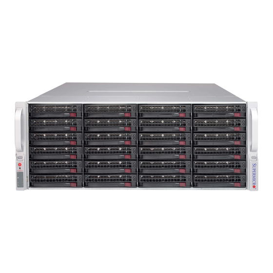
Chapter 1 Introduction Overview Optimized for enterprise-level heavy-capacity storage applications, Supermicro's SC847 chassis features 36x (24 front + 12 rear) 3.5" hot-swap HDD bays used as a server chassis. The SC847 design provides high-density storage in a 4U form factor, with high power efficiency, optimized HDD signal trace routing and improved HDD carrier design to dampen vibration and maximize performance. -
Page 10: Where To Get Replacement Components
Supermicro Authorized Distributors/ System Integrators/Resellers. A list of Supermicro Authorized Distributors/System Integrators/Resellers can be found at: http://www.supermicro.com. Click the Where to Buy link. -
Page 11: Contacting Supermicro
Super Micro Computer, Inc. 980 Rock Ave. San Jose, CA 95131 U.S.A. Tel: +1 (408) 503-8000 Fax: +1 (408) 503-8008 Email: marketing@supermicro.com (General Information) support@supermicro.com (Technical Support) Web Site: www.supermicro.com Europe Address: Super Micro Computer B.V. Het Sterrenbeeld 28, 5215 ML... -
Page 12: Returning Merchandise For Service
For faster service, RMA authorizations may be requested online (http://www. supermicro.com/support/rma/). Whenever possible, repack the chassis in the original Supermicro carton, using the original packaging material. If these are no longer available, be sure to pack the chassis securely, using packaging material to surround the chassis so that it does not shift within the carton and become damaged during shipping. -
Page 13: Chapter 2 System Safety
Chapter 2: System Safety Chapter 2 System Safety Overview This chapter provides a quick setup checklist to get your chassis up and running. Following the steps in order given should enable you to have your chassis set up and operational within a minimal amount of time. This quick setup assumes that you are an experienced technician, famailiar with common concepts and terminology. -
Page 14: Electrical Safety Precautions
SC847 Chassis Manual Electrical Safety Precautions Basic electrical safety precautions should be followed to protect yourself from harm and the SC847 from damage: • Be aware of the locations of the power on/off switch on the chassis as well as the room’s emergency power-off switch, disconnection switch or electrical outlet. -
Page 15: General Safety Precautions
Chapter 2: System Safety • Please handle used batteries carefully. Do not damage the battery in any way; a damaged battery may release hazardous materials into the environment. Do not discard a used battery in the garbage or a public landfill. Please comply with the regulations set up by your local hazardous waste management agency to dispose of your used battery properly. - Page 16 SC847 Chassis Manual • Touch a grounded metal object before removing any board from its antistatic bag. • Do not let components or PCBs come into contact with your clothing, which may retain a charge even if you are wearing a wrist strap. •...
-
Page 17: Chapter 3 System Interface
Chapter 3: System Interface Chapter 3 System Interface Overview There are several LEDs on the control panel as well as others on the drive carriers to keep you constantly informed of the overall status of the system as well as the activity and health of specific components. -
Page 18: Control Panel Buttons
SC847 Chassis Manual Control Panel Buttons There are two push-buttons located on the left handle of the chassis. These are (in order from top to bottom) a power on/off button and a reset button. Power: The main power button is used to apply or remove power from the power supply to the server system. - Page 19 Chapter 3: System Interface NIC1: Indicates network activity on GLAN1 when flashing. NIC2: Indicates network activity on GLAN2 when flashing. Overheat/Fan Fail: When this LED flashes, it indicates a fan failure. When con- tinuously on (not flashing) it indicates an overheat condition, which may be caused by cables obstructing the airflow in the system or the ambient room temperature being too warm.
-
Page 20: Drive Carrier Leds
SC847 Chassis Manual Drive Carrier LEDs Your chassis uses SAS/SATA. SAS/SATA Drives Each SAS/SATA drive carrier has two LEDs. • Blue: Solid on = Drive is present and available. Blinking = Drive is actively being accessed. Each Serial ATA drive carrier has a blue LED. When illuminated in a solid on state, this blue LED (on the front of the SAS/SATA drive carrier) indicates drive activity. -
Page 21: Chapter 4 Chassis Setup And Maintenance
Chapter 4: Chassis Setup and Maintenance Chapter 4 Chassis Setup and Maintenance Overview This chapter covers the steps required to install components and perform mainte- nance on the chassis. The only tool you will need to install components and perform maintenance is a Phillips screwdriver. -
Page 22: Removing The Chassis Cover
SC847 Chassis Manual Removing the Chassis Cover Figure 4-1: Removing the Chassis Cover Removing the Chassis Cover Unplug the chassis from any power source Remove the screws securing the cover to the chassis. Lift the cover up and off the chassis. Warning: Except for short periods of time, do NOT operate the server without the cover in place. -
Page 23: Installing Removable Hard Drives
Chapter 4: Chassis Setup and Maintenance Installing Removable Hard Drives Figure 4-2: Removing Hard Drive Removing Hard Drive Carriers from the Chassis Press the release button on the drive carrier. This extends the drive carrier handle. Use the handle to pull the drive carrier out of the chassis. - Page 24 Figure 4-4: Removing the Dummy Drive from the Carrier Warning! Enterprise level hard disk drives are recommended for use in Supermicro chassis and servers. For information on recommended HDDs, visit the Supermicro Web site at http:// www.supermicro.com/products/nfo/files/storage/SAS-1-Com- pList-110909.pdf...
- Page 25 Chapter 4: Chassis Setup and Maintenance SAS/SATA Hard Drive Drive Carrier Figure 4-5: Installing the Hard Drive into the Carrier Slide the hard drive into the carrier with the printed circuit board side facing down. Carefully align the mounting holes in both the drive carrier and the hard drive. Secure the hard drive to the carrier using six screws.
-
Page 26: Installing Optional Fixed Hard Drives (Tray P/N: Mcp-220-84701-0N)
SC847 Chassis Manual Installing Optional Fixed Hard Drives (Tray p/n: MCP-220-84701-0N) The SC847 chassis includes brackets for installing either one 3.5" fixed hard drive, or two 2.5" fixed hard drives within the chassis. Each chassis can accomodate up to two internal drive trays supporting up to two 3.5" hard drives or up to four 2.5" hard drives. -
Page 27: Installing The Motherboard
[0.197] [0.197] Chapter 4: Chassis Setup and Maintenance DVD-ROM, CD-ROM, and FLOPPY DRIVE Installing the Motherboard Flat head Round h Round head Pan head Permanent and Optional Standoffs 6-32 x 5 mm M2.6 x 5 M3 x 5 mm 6-32 x 5 mm [0.197] [0.19 [0.197]... - Page 28 SC847 Chassis Manual Figure 4-10: Motherboard Installation Lay the motherboard on the chassis aligning the permanent and optional standoffs Secure the motherboard to the chassis using the rounded, Phillips head screws. Do not exceed eight pounds of torque per square inch when tighten- ing down the motherboard.
-
Page 29: Add-On Card/Expansion Slot Setup
Chapter 4: Chassis Setup and Maintenance Add-on Card/Expansion Slot Setup SC847: The chassis includes I/O slots for expansion cards. The number of cards used depends on your chassis model. SC847 LP Models: Provides seven low-profile expansion card slots. SC847 UIO Models: Provides three full-height/full-length slots, three low-profile slots and includes a universal expansion card. -
Page 30: Expansion Slot Setup In U (Universal Output) Chassis
SC847 Chassis Manual Expansion Slot Setup in U (Universal Output) Chassis SC847 U model chassis accepts a slightly smaller "L" shaped motherboard to allow for a universal expansion card. This universal output card allows the systems to accept SAS, SCSI, IB, Ethernet, and other types of connections. SC847 U chassis accepts three full-length, full-height add-on cards and the fourth slot is used for the UI/O card. -
Page 31: Installing The Air Shroud
Chapter 4: Chassis Setup and Maintenance Installing the Air Shroud Figure 4-13: Air Shroud for SC847LP Chassis Air shrouds concentrate airflow to maximize fan efficiency. The SC847 chassis air shroud does not require screws for its installation. The SC847 air shroud is designed with removeable break-away tabs that allow the air shroud to be adjusted to fit a variety of motherboards. -
Page 32: Checking The Server's Air Flow
SC847 Chassis Manual Checking the Server's Air Flow Checking the Air Flow 1. Make sure there are no objects to obstruct airflow in and out of the server. In addition, if you are using a front bezel, make sure the bezel's filter is replaced periodically. -
Page 33: System Fans
Chapter 4: Chassis Setup and Maintenance System Fans Seven hot-swappable, heavy-duty fans provide cooling for the chassis. These fans circulate air through the chassis thereby lowering the chassis internal tempera- ture. Release Tab Air Direction Indicator Figure 4-14: System Fan Replacing a System Fan Open the chassis while the power is running to determine which fan has failed. - Page 34 SC847 Chassis Manual Figure 4-15: Placing the System Fan 4-14...
-
Page 35: Power Supply
An illuminated green light indicates that the power supply is operating. Redundant power supplies are hot-swappable, and can be changed without pow- ering down the system. New units can be ordered directly from Supermicro (see contact information in the Preface). Release Tab... - Page 36 SC847 Chassis Manual Notes 4-16...
-
Page 37: Chapter 5 Rack Installation
Chapter 5: Rack Installation Chapter 5 Rack Installation Overview This chapter provides a quick setup checklist to get your chassis up and running. Following these steps in the order given should enable you to have the system operational within a minimal amount of time. Unpacking the System You should inspect the box which the chassis was shipped in and note if it was damaged in any way. -
Page 38: Warnings And Precautions
SC847 Chassis Manual Warning! Warnings and Precautions Rack Precautions • Ensure that the leveling jacks on the bottom of the rack are fully extended to the floor with the full weight of the rack resting on them. • In single rack installations, stabilizers should be attached to the rack. •... -
Page 39: Rack Mounting Considerations
Chapter 5: Rack Installation • Always keep the rack's front door and all panels and components on the servers closed when not servicing to maintain proper cooling. Rack Mounting Considerations Ambient Operating Temperature If installed in a closed or multi-unit rack assembly, the ambient operating tempera- ture of the rack environment may be greater than the ambient temperature of the room. -
Page 40: Rack Mounting Instructions
SC847 Chassis Manual Rack Mounting Instructions This section provides information on installing the chassis into a rack unit with the rails provided. There are a variety of rack units on the market, which may mean that the assembly procedure will differ slightly from the instructions provided. You should also refer to the installation instructions that came with the rack unit you are using. -
Page 41: Locking Tabs
Chapter 5: Rack Installation Locking Tabs Each inner rail has a locking tab. This tab locks the chassis into place when installed and pushed fully into the rack. These tabs also lock the chassis in place when fully extended from the rack. This prevents the server from coming completely out of the rack when when the chassis is pulled out for servicing. -
Page 42: Installing The Inner Rails On The Chassis
SC847 Chassis Manual Inner Rails Figure 5-3: Installing the Inner Rails Figure 5-4: Inner Rails Installed on the Chassis Installing The Inner Rails on the Chassis Installing the Inner Rails Confirm that the left and right inner rails have been correctly identified. Place the inner rail firmly against the side of the chassis, aligning the hooks on the side of the chassis with the holes in the inner rail. -
Page 43: Installing The Outer Rails On The Rack
Chapter 5: Rack Installation L-min=676.00(26.61")(outer rail) 21D01 Figure 5-5: Extending and Releasing the Outer Rails Installing the Outer Rails on the Rack Installing the Outer Rails Press upward on the locking tab at the rear end of the middle rail. Push the middle rail back into the outer rail. -
Page 44: Standard Chassis Installation
SC847 Chassis Manual Ball-Bearing Shuttle Figure 5-6: Installing into a Rack Standard Chassis Installation Installing the Chassis into a Rack Confirm that the inner rails are properly installed on the chassis. Confirm that the outer rails are correctly installed on the rack. Pull the middle rail out from the front of the outer rail and make sure that the ball-bearing shuttle is at the front locking position of the middle rail. -
Page 45: Optional Quick Installation Method
Chapter 5: Rack Installation Optional Quick Installation Method The following quick installation method may be used to install the chassis onto a rack. Installing the Chassis into a Rack Install the whole rail assembly onto the rack as described on page 5-7. Release the inner rail without retracting the middle rail. -
Page 46: Adapters For Round And Threaded Hole Racks
SC847 Chassis Manual Adapters for Round and Threaded Hole Racks The SC847 chassis includes adapter brackets for those customers using round hole racks or racks with threaded holes size M5 or larger. Installing the Adapter Bracket Place the hooks of the front of the outer rail into the square holes of one of the adapter brackets. -
Page 47: Appendix A Sc847 Cables And Hardware
This appendix lists supported cables for your chassis system. It only includes the most commonly used components and configurations. For more compatible cables, refer to the manufacturer of the motherboard you are using and our Web site at: www.supermicro.com. A-2 Cables Included with SC847 Chassis (SAS/SATA) SC847... - Page 48 SC847 Chassis Manual A-3 Compatible Cables These cables are compatible with the SC847 Chassis. Alternate SAS/SATA Cables Some compatible motherboards have different connectors. If your motherboard has only one SAS connector that the SAS/SATA cables must share, use one of the following cables.
-
Page 49: Extending Power Cables
Appendix A: Chassis Cables Extending Power Cables Although Supermicro chassis are designed with to be efficient and cost-effective, some compatible motherboards have power connectors located in different areas. To use these motherboards you may have to extend the power cables to the mother boards. - Page 50 SC847 Chassis Manual A-4 Chassis Screws The accessory box includes all the screws needed to set up your chassis. This section lists and describes the most common screws used. Your chassis may not require all the parts listed. HARD DRIVE Flat head Pan head 6-32 x 5 mm...
-
Page 51: Appendix B Sc847 Power Supply Specifications
Appendix B: Power Supply Specifications Appendix B SC847 Power Supply Specifications This appendix lists power supply specifications for your chassis system. SC847 1400W MFR Part # PWS-1K41P-1R 1100W: 100 - 140V, 50 - 60Hz, 9.5 - 13.5 Amp AC Input 1400W: 180 - 240V, 50 - 60Hz, 7.0 - 9.5 Amp DC Output 4 Amp... - Page 52 SC847 Chassis Manual Notes...
-
Page 53: Appendix C Sas-826A Backplane Specifications
Appendix C: SAS-826A Backplane Specifications Appendix C SAS-826A Backplane Specifications To avoid personal injury and property damage, carefully follow all the safety steps listed below when accessing your system or handling the components. C-1 ESD Safety Guidelines Electrostatic Discharge (ESD) can damage electronic com ponents. To prevent dam- age to your system, it is important to handle it very carefully. - Page 54 This manual reflects SAS-826A Revision 1.00, the most current release available at the time of publication. Always refer to the Supermicro Web site at www.supermicro. com for the latest updates, compatible parts and supported configurations.
-
Page 55: Front Connectors
Appendix C: SAS-826A Backplane Specifications C-5 Front Connectors and Jumpers SAS826A C202 JP25 JP84 REV 1.00 JP84:MODE 1-2:SGPIO ALARM#1 C215 2-3:I2C R325 9071 RST C285 9072 RST JP69 C198 R376 JP25:OH#1 TEMP UPGRADE#1 DESIGNED IN USA OPEN:45 1-2:50 JP78 2-3:55 C271 C272 C201 C208... - Page 56 SC847 Chassis Manual C-6 Front Connector and Pin Definitions #1. Activity LED Headers SAS Activity LED Header Pin Definitions The activity LED headers, designated JP26 Pin # Definition Pin # Definition and JP47, are used to indicate the activity ACT IN#0 ACT IN#4 status of each SAS drive.
- Page 57 Appendix C: SAS-826A Backplane Specifications #6. Backplane Main Power Connectors Backplane Main Power The 4-pin connectors, designated JP10, 4-Pin Connector JP13, and JP46 provide power to the Pin# Definition backplane. See the table on the right for +12V pin definitions. 2 and 3 Ground #7., #8., #9.
-
Page 58: Explanation Of Jumpers
SC847 Chassis Manual C-7 Front Jumper Locations and Pin Definitions JP84 SAS826A C202 JP25 JP84 JP50 REV 1.00 JP84:MODE 1-2:SGPIO ALARM#1 C215 2-3:I2C R325 JP35 9071 RST C285 9072 RST JP69 C198 R376 JP25:OH#1 TEMP UPGRADE#1 DESIGNED IN USA OPEN:45 1-2:50 JP78 2-3:55... - Page 59 Appendix C: SAS-826A Backplane Specifications C and SGPIO Modes and Jumper Settings This backplane can utilize I C or SGPIO. SGPIO is the default mode and can be used without making changes to your jumpers. The following information details which jumper must be configured to use SGPIO mode or restore your backplane to I C mode.
-
Page 60: Front Led Indicators
SC847 Chassis Manual Front LED Indicators SAS826A C202 JP25 JP84 REV 1.00 JP84:MODE 1-2:SGPIO ALARM#1 C215 2-3:I2C R325 9071 RST C285 9072 RST JP69 C198 R376 JP25:OH#1 TEMP UPGRADE#1 DESIGNED IN USA OPEN:45 1-2:50 JP78 2-3:55 C271 C272 C201 C208 R226 R249 R257... - Page 61 Appendix C: SAS-826A Backplane Specifications C-8 Rear Connectors and LED Indicators R174 SAS #2 SAS #11 SAS #8 SAS #5 SAS #1 SAS #7 SAS #10 SAS #4 SAS826A SAS #0 SAS #3 SAS #9 REV 1.00 SAS #6 Figure C-4: Rear Connectors and LEDs Rear SAS/SATA Connectors Rear SAS Drive...
- Page 62 SC847 Chassis Manual Notes C-10...
-
Page 63: Appendix D Sas-846A Backplane Specifications
Appendix D: SAS-846A Backplane Specifications Appendix D SAS-846A Backplane Specifications To avoid personal injury and property damage, carefully follow all the safety steps listed below when accessing your system or handling the components. D-1 ESD Safety Guidelines Electrostatic Discharge (ESD) can damage electronic com ponents. To prevent dam- age to your system, it is important to handle it very carefully. - Page 64 This manual reflects SAS-846A Revision 1.00, the most current release available at the time of publication. Always refer to the Supermicro Web site at www.supermicro. com for the latest updates, compatible parts and supported configurations.
- Page 65 Appendix D: SAS-846A Backplane Specifications D-5 Front Connectors and Components JP107 JP107:OH#3 TEMP. JP45 C359 JP45:OH#2 TEMP. BUZZER RESET OPEN:45 OPEN:45 1-2:50 1-2:50 JP25:OH#1 TEMP. R324 2-3:55 2-3:55 R325 OPEN:45 1-2:50 C282 JP106 JP105 2-3:55 CH#20~23 CH#8~11 JSM6 JSM3 JP129:9072#3 RESET 1-2: RESET 2-3: NO RESET C326...
- Page 66 SC847 Chassis Manual D-6 Front Connector and Pin Definitions 1. MG9072 Chip The MG9072 is an enclosure management chip that supports the SES-2 controller and SES-2 protocols. 2. Upgrade Connectors The upgrade connectors are designated JP69, JP78, and JP115 and are used for manufactur- er's diagnostic purposes only.
-
Page 67: Jumper Settings
Appendix D: SAS-846A Backplane Specifications D-7 Front Jumper Locations and Pin Definitions JP97 JP18 JP98 JP129 JP107 JP107:OH#3 TEMP. JP45 JP45:OH#2 TEMP. C359 JP99 OPEN:45 BUZZER RESET OPEN:45 1-2:50 1-2:50 JP25:OH#1 TEMP. R324 2-3:55 2-3:55 R325 OPEN:45 1-2:50 C282 JP106 JP105 2-3:55 CH#20~23... -
Page 68: Fan Jumper Settings
SC847 Chassis Manual Fan Jumper Settings This backplane can use up to four fans. To utilize each fan, you must configure both jumpers as indicated below. Fan Jumper Settings Jumper Jumper Settings Note 1-2: With Fan (Default) FAN#1 JP61 2-3: No Fan 1-2: With Fan (Default) FAN#1 JP97... - Page 69 Appendix D: SAS-846A Backplane Specifications Front LED Indicators JP25:OH#1 TEMP. OPEN:45 1-2:50 2-3:55 JP107 JP107:OH#3 TEMP. JP45 JP45:OH#2 TEMP. C359 BUZZER RESET OPEN:45 OPEN:45 1-2:50 1-2:50 JP25:OH#1 TEMP. R324 2-3:55 2-3:55 R325 OPEN:45 1-2:50 C282 JP106 JP105 2-3:55 CH#20~23 CH#8~11 JSM6 JSM3 JP129:9072#3 RESET...
- Page 70 SC847 Chassis Manual D-8 Rear Connectors and LED Indicators SAS #11 SAS #17 SAS #23 SAS #5 SAS #10 SAS #16 SAS #22 SAS #4 SAS #3 SAS #9 SAS #15 SAS #21 SAS #2 SAS #14 SAS #20 SAS #8 SAS #1 SAS #7 SAS #13...
- Page 71 Appendix D: SAS-846A Backplane Specifications Rear LED Indicators Rear LED Hard Drive Activity Failure LED SAS #0 SAS #1 SAS #2 SAS #3 SAS #4 SAS #5 SAS #6 SAS #7 SAS #8 SAS #9 SAS #10 SAS #11 SAS #12 SAS #13 SAS #14 SAS #15...
- Page 72 SC847 Chassis Manual Notes D-10...
-
Page 73: Appendix E Sas-826El Backplane Specifications
Appendix E: SAS-826EL Backplane Specifications Appendix E SAS-826EL Backplane Specifications To avoid personal injury and property damage, carefully follow all the safety steps listed below when accessing your system or handling the components. ESD Safety Guidelines Electrostatic Discharge (ESD) can damage electronic com ponents. To prevent dam- age to your system, it is important to handle it very carefully. - Page 74 This manual reflects SAS-826EL Revision 1.02, the most current release available at the time of publication. Always refer to the Supermicro Web site at www.supermicro. com for the latest updates, compatible parts and supported configurations.
- Page 75 Appendix E: SAS-826EL Backplane Specifications Front Connectors and Jumpers 12V_LED 5V_LED BAR CODE FANFAIL1 PRI_MODE4 SEC_MODE4 REMOTE_FAN_FAIL_SCOKET BUZZER_ENB1 SAS826EL REV 1.02 +12V +12V DESIGNED IN USA Figure E-1: SAS-826EL2 Connectors and Components Front Connectors EPP connectors: J16 and J17 Primary SAS connectors: PRI_J0 Primary and secondary flash Primary SAS connectors: PRI_J1 chips...
- Page 76 SC847 Chassis Manual Front Connector and Pin Definitions 1. EPP Ports The EPP ports are used for manufacturer di- agnostic purposes only. 2. Primary and Secondary Flash Chips The Primary and Secondary Flash Chips en- hance the backplane memory. 3. Primary and Secondary Expander Chips This Primary and Secondary Expander Chips allow the backplane to support dual port, cas- cading, and failover configurations.
- Page 77 Appendix E: SAS-826EL Backplane Specifications Front Jumper Locations and Pin Definitions PRI_Mode4 BAR CODE SEC_MODE4 12V_LED 5V_LED SEC_Mode4 FANFAIL1 PRI_MODE4 REMOTE_FAN_FAIL_SCOKET Remote Fan Fail Socket 12V_LED 5V_LED BAR CODE FANFAIL1 PRI_MODE4 SEC_MODE4 REMOTE_FAN_FAIL_SCOKET BUZZER_ENB1 SAS826EL REV 1.02 +12V +12V DESIGNED IN USA Figure E-3: Front Jumpers DESIGNED IN USA Explanation of Jumpers...
- Page 78 SC847 Chassis Manual General Jumper Settings Jumper Jumper Settings Note Factory setting PRI_MODE4 do not change Factory setting SEC_MODE4 do not change Socket Settings Socket Socket Setting Note REMOTE_FAN_FAIL_ Front panel fan fail indicator Open SOCKET (optional)
- Page 79 Appendix E: SAS-826EL Backplane Specifications Front LED Indicators Fan Fail LED 12V_LED 5V_LED 12V_LED 5V_LED FANFAIL1 PRI_MODE4 REMOTE_FAN_FAIL_SCOKET Overheat LED SAS826EL 12V_LED 5V_LED BAR CODE FANFAIL1 PRI_MODE4 SEC_MODE4 REMOTE_FAN_FAIL_SCOKET REV 1.02 BUZZER_ENB1 SAS826EL REV 1.02 DESIGNED IN USA +12V +12V DESIGNED IN USA Figure E-4: Front LEDs Backplane LEDs...
- Page 80 SC847 Chassis Manual Rear Connectors and LED Indicators ACT#2 ACT#11 ACT#8 ACT#5 FAIL#2 FAIL#11 FAIL#8 FAIL#5 SAS #11 SAS #2 SAS #8 SAS #5 ACT#7 ACT#1 ACT#4 ACT#10 FAIL#7 FAIL#1 FAIL#4 FAIL#10 SAS #7 SAS #1 SAS #4 SAS #10 ACT#3 ACT#9 ACT#0...
-
Page 81: Single Ports
Appendix E: SAS-826EL Backplane Specifications Single and Dual Port Expanders Single Ports SAS-826EL1 backplanes have a single-port expander that access all twelve drives and supports cascading. Dual Ports SAS-826EL2 backplanes have dual-port expanders that access all twelve drives. These dual-port expanders support cascading, failover, and recovery. Warning: The SAS 826EL2 backplane's J0 and J1 SAS ports are reversed in the Secondary Expander Port B with J0 on top and J1 on the bottom. - Page 82 SC847 Chassis Manual E-10 Failover The SAS-826EL2 Backplane has two expanders which allow effective failover and recovery. Single Host Bus Adapter SAS HBA In a single host bus configuration, the backplane connects to one Host Bus Adapter (HBA). Port B Port A Expander 2 Expander 1...
- Page 83 Other servers in this enclosed system include a power card. This section describes the supported power card for the 826 backplane system. For more information, see the PCC-JBPWR2 power card manual. This manual can be found at the http://www.supermicro.com or as an appendix in the SC847 chassis manual. JBPWR2 REV 1.00...
- Page 84 SC847 Chassis Manual Connecting an Internal Host Bus Adapter to the Backplane The following section lists the most common cables used to connect the HBA to the backplane. Single Internal Host Bus Adapter (Host Bus Adapter) Dual Internal Host Bus Adapter (Host Bus Adapter) (Host Bus Adapter) Figure E-8: Connecting to Single and Dual Internal HBAs...
- Page 85 Appendix E: SAS-826EL Backplane Specifications Supported Internal HBA to Backplane Cables Use the following listed cables to create connections between the internal HBA and backplane. The cables required depend on the HBA connector. Cable Name: iPass TO 4-LANE Part #: CBL-0117 Length: 46 cm (18 inches) Description: This cable has one SFF-8484 (32 pin) connector on one end and ipass (SFF-8087/mini-SAS) connector (36 pins) at the other.
- Page 86 SC847 Chassis Manual Connecting an External Host Bus Adapter to the Backplane This backplane supports external HBAs. In this configuration, the HBA and the backplane are in different physical chassis. This allows a JBOD (Just a Bunch Of Drives) configuration from an existing system. Single External Host Bus Adapter Power Card (Host Bus Adapter)
- Page 87 Appendix E: SAS-826EL Backplane Specifications Supported External HBA to Backplane Cable Use the following cable if your external HBA has an InfiniBand connector. Figure E-10: The CBL-0200L Cable Cable Name: SAS InfiniBand to mini SAS X4 1M cable, PBF Part #: CBL-0200L Length: 1 meter Description: This cable has an InfiniBand connector (SFF-8470) on one end and an SFF-8088-1X (26-pins) at the other end.
- Page 88 SC847 Chassis Manual Connecting Multiple Backplanes in a Single Channel Environment This section describes the cables used when cascading from a single HBA. These connections use CBL-0167L internal cables and CBL-0166L external cables. Single HBA Configuration CBL-0167L with Single Port Assembly (internal cable) (Host Bus Adapter) CBL-0166L...
- Page 89 Appendix E: SAS-826EL Backplane Specifications Single HBA Configuration Cables Single Port Cable Assembly Figure E-12: The CBL-0167L Cable Cable Name: SAS EL2/EL1 Backplane Cable (Internal) w/ 2-port Cascading Cable, 68 cm Part #: CBL-0167L (SFF-8087 to SFF-8088 x1) Ports: Single Placement: Internal cable Description: Internal cable.
- Page 90 SC847 Chassis Manual Connecting Multiple Backplanes in a Dual Channel Environment This section describes the cables used when cascading from a single HBA. These connections use CBL-0168L internal cables and CBL-0166L external cables. CBL-0168L with Single Port Assembly (internal cable) (Host Bus Adapter) (Host Bus Adapter) CBL-0166L...
- Page 91 Appendix E: SAS-826EL Backplane Specifications Dual HBA Configuration Cables Dual Port Cable Assembly Figure E-15: The CBL-0168L Cable Cable Name: SAS Dual-port Cable Assembly, 68/76cm Part #: CBL-0168L (SFF-8087 to SFF-8088 x2 Ports: Dual Placement: Internal cable Description: Internal cascading cable. Connects the backplane to the Host Bus Adapter (HBA) or external port.
- Page 92 SC847 Chassis Manual E-12 Supported Cascading Configuration Cascading allows the system to access data at a faster rate by allowing several backplanes to share resources to reduce latency time. The first backplane in a cascaded system requires a motherboard and HBA. Other servers require a power control card, not a motherboard and HBA.
- Page 93 Appendix E: SAS-826EL Backplane Specifications Server System with Dual SAS HBA and Cascading Configuration CBL-0168L with Dual Port Assembly (internal cable) (Host Bus Adapter) (Host Bus Adapter) CBL-0166L (External cable) Power Card Power Card E-21...
- Page 94 SC847 Chassis Manual Notes E-22...
-
Page 95: Appendix F Sas-846El Backplane Specifications
Appendix F: SAS-846EL Backplane Specifieations Appendix F SAS-846EL Backplane Specifications To avoid personal injury and property damage, carefully follow all the safety steps listed below when accessing your system or handling the components. ESD Safety Guidelines Electrotatic Discharge (ESD) can damage electronic com ponents. To prevent damage to your system, it is important to handle it very carefully. - Page 96 This manual reflects SAS-846EL Revision 1.10, the most current release available at the time of publication. Always refer to the Supermicro Web site at www.supermicro. com for the latest updates, compatible parts and supported configurations.
- Page 97 Appendix F: SAS-846EL Backplane Specifieations Front Connectors and Jumpers REMOTE_FAN_FAIL_SOCKET1 BUZZER_ENB1 OVERHEATFAIL1 FANFAIL1 SEC_J2 SEC_J1 SEC_J0 PRI_J2 PRI_J1 PRI_J0 SEC_I2C1 SEC_IPMI1 PRI_IPMI1 BUZZER1 PRI_I2C1 SAS846EL2 REV 1.01 BAR CODE DESIGNED IN USA SEC_EXP1 S_J1 PRI_FLASH1 SEC_FLASH1 PRI_EXP1 P_J1 1J24 R227 EC22 5V_LED1 PWR5...
- Page 98 SC847 Chassis Manual Front Connector and Pin Definitions 1. and 2. Optional Primary and Secondary C Connector C Connectors Pin Definitions Pin# Definition The optional I C connectors are connected to Data the CSE-PTJBOD-CB2 board and are used Ground to monitor the power supply status and to Clock control the fans.
- Page 99 Appendix F: SAS-846EL Backplane Specifieations 7. Fan Connectors Fan Connectors The 3-pin connectors, designated FAN1, Pin# Definition FAN2, and FAN3, provide power to the Ground fans. See the table on the right for pin +12V definitions. Tachometer 8 - 13. SAS Ports The primary and secondary sets of SAS ports provide expander features including cascading and failover From right to left...
- Page 100 SC847 Chassis Manual Front Jumper Locations and Pin Definitions REMOTE_FAN_FAIL_SOCKET1 OVERHEATFAIL1 FANFAIL1 SEC_MODE1 REMOTE_FAN_FAIL_SOCKET1 BUZZER_ENB1 OVERHEATFAIL1 FANFAIL1 SEC_J2 SEC_J1 SEC_J0 PRI_J2 PRI_J1 PRI_J0 SEC_I2C1 SEC_IPMI1 PRI_IPMI1 BUZZER1 PRI_I2C1 SAS846EL2 REV 1.01 BAR CODE DESIGNED IN USA SEC_EXP1 S_J1 PRI_FLASH1 SEC_FLASH1 PRI_EXP1 P_J1 1J24...
- Page 101 Appendix F: SAS-846EL Backplane Specifieations General Jumper Settings Jumper Jumper Settings Note Factory Setting PRI_MODE1 Do not change Factory Setting SEC_MODE1 Do not change Socket Settings Socket Socket Setting Note REMOTE_FAN_FAIL_ Front Panel Fan Fail indicator Connected SOCKET (Optional) Front Panel LEDs State Specification Overheat/Drive Failure LED Indicator...
- Page 102 SC847 Chassis Manual Rear Connectors and LED Indicators SAS #5 SAS #11 SAS #17 SAS #23 C562 C405 C409 C431 C435 C532 C536 C558 SAS #4 SAS #16 SAS #22 SAS #10 C557 C404 C408 C430 C434 C531 C535 C561 SAS #3 SAS #15 SAS #9...
- Page 103 Appendix F: SAS-846EL Backplane Specifieations Rear LED Indicators Rear Connector Hard Drive Activity LED Failure LED SAS #0 ACT #0 FAIL #0 SAS #1 ACT #1 FAIL #1 SAS #2 ACT #2 FAIL #2 SAS #3 ACT #3 FAIL #3 SAS #4 ACT #4 FAIL #4...
- Page 104 SC847 Chassis Manual Dual Port and Cascading Configurations Single and Dual Port Expanders Single Ports SAS-846EL1 backplanes have a single-port expander that access all twenty-four drives and supports cascading. Dual Ports SAS-846EL2 backplanes have dual-port expanders that access all twenty-four drives.
-
Page 105: Single Host Bus Adapter
Appendix F: SAS-846EL Backplane Specifieations F-10 Failover The SAS-846EL2 backplane has two expanders which allow effective failover. Single Host Bus Adapter SAS HBA In a single host bus configuration, the backplane connects to one Host Bus Adapter (HBA). PRI_J2 SEC_J2 PRI_J1 SEC_J0 SEC_J1... - Page 106 This section describes the supported power card for the SAS-846 series backplane. For more information, see the PCC-JBPWR2 power card manual. This manual can be found at the http://www.supermicro.com. JBPWR2 REV 1.00 Figure F-10: Chassis Power Card (Sold Separately)
- Page 107 Appendix F: SAS-846EL Backplane Specifieations Connecting an Internal Host Bus Adapter to the Backplane The following section lists the most common cables used to connect the Host Bus Adapter (HBA) to the backplane. PRI_J2 SEC_J2 PRI_J1 SEC_J0 SEC_J1 PRI_J0 (Host Bus Adapter) Figure F-11: Single Internal Host Bus Adapter PRI_J2 SEC_J2...
- Page 108 SC847 Chassis Manual Cable Name: iPass (mini SAS) to iPass (mini SAS) Part #: CBL-0108L-02 Length: 39 cm (15 inches) Part #: CBL-0109L-02 Length: 22 cm (9 inches) Part #: CBL-0110L-02 Length: 18 cm (7 inches) Description: This cable has an iPass (SFF-8087/mini-SAS) connector (36 pins) at each end.
- Page 109 Appendix F: SAS-846EL Backplane Specifieations Connecting an External Host Bus Adapter to the Backplane This backplane supports external Host Bus Adapters. In this configuration, the HBA and the backplane are in different physical chassis. This allows a JBOD configura- tion system to connect to the other system that has a HBA. Single External Host Bus Adapter PRI_J2 SEC_J2...
- Page 110 SC847 Chassis Manual Supported External HBA to Backplane Cable Use the following cable if your external HBA has an InfiniBand connector. Figure F-15: SAS InfiniBand Cable (CBL-0200L) Cable Name: SAS InfiniBand to Mini SAS X4 1M cable, PBF Part #: CBL-0200L Length: 1 meter Description: This cable has an InfiniBand connector (SFF-8470) on one end and an SFF-8088-1X (26-pins) at the other end.
- Page 111 Appendix F: SAS-846EL Backplane Specifieations Connecting Multiple Backplanes in a Single Channel Environment This section describes the cables used when cascading from a single HBA. These connections use CBL-0167L internal cables and CBL-0166L external cables. CBL-0167L with Single Port Assembly PRI_J2 SEC_J2 PRI_J1...
- Page 112 SC847 Chassis Manual Single HBA Configuration Cables Single Port Cable Assembly Figure F-17: Single Port Internal Cable (CBL-0167L) Cable Name: SAS EL2/EL1 Backplane Cable (Internal) with 2-port Cascading Cable, 68 cm Part #: CBL-0167L (SFF-8087 to SFF-8088 x1) Ports: Single Placement: Internal cable Description: Internal cable.
- Page 113 Appendix F: SAS-846EL Backplane Specifieations Connecting Multiple Backplanes in a Dual Channel Environment This section describes the cables used when cascading from dual HBAs. These connections use CBL-0168L internal cables and CBL-0166L external cables. PRI_J2 SEC_J2 PRI_J1 SEC_J0 SEC_J1 PRI_J0 Cable 0168L Port B Expander 2 Port A Expander 1...
- Page 114 SC847 Chassis Manual Dual HBA Configuration Cables Dual Port Cable Assembly Figure F-20: Dual Port Internal Cable (CBL-0168L) Cable Name: SAS Dual-port Cable Assembly, 68/76cm Part #: CBL-0168L Placement: Internal cable Ports: Dual Description: Internal cascading cable. Connects the backplane to the Host Bus Adapter (HBA) or external port.
- Page 115 The first backplane in a cascaded system requires a motherboard and HBA. Other servers require a power control card with no motherboard and no HBA. For more information, see the SC846 Chassis Manual available at www.supermicro.com. SEC_J2 PRI_J2...
- Page 116 SC847 Chassis Manual Server System with Single SAS HBA The expanders allow horizontal branching. This configuration also applies to dual ports. PRI_J2 PRI_J2 SEC_J2 PRI_J1 SEC_J2 PRI_J1 SEC_J0 SEC_J1 SEC_J0 SEC_J1 PRI_J0 PRI_J0 Port A Expander 1 Port A Expander 1 Power Card Cable 0167L (internal cable)
- Page 117 Appendix F: SAS-846EL Backplane Specifieations Dual SAS HBA and Cascaded Configuration PRI_J2 SEC_J2 PRI_J1 SEC_J0 SEC_J1 PRI_J0 Port A Expander 1 Port B Expander 2 Dual Port Cable Assembly Cable 0168L (internal cable) Cable 0166L PRI_J2 SEC_J2 PRI_J1 SEC_J0 SEC_J1 (external cables) PRI_J0 Port B Expander 2...
- Page 118 SC847 Chassis Manual Dual SAS HBA and Cascaded Configuration with Branching Port B Ex. 2 Port A Ex. 1 Port B Ex. 2 Port A Ex. 1 Power Card Port B Ex. 2 Port A Ex. 1 Port B Ex. 2 Port A Ex. 1 Power Power Card...
- Page 119 Appendix F: SAS-846EL Backplane Specifieations Notes F-25...
- Page 120 SC847 Chassis Manual Disclaimer (cont.) The products sold by Supermicro are not intended for and will not be used in life sup- port systems, medical equipment, nuclear facilities or systems, aircraft, aircraft devices, aircraft/emergency communication devices or other critical systems whose failure to per- form be reasonably expected to result in significant injury or loss of life or catastrophic property damage.