
Related Manuals for Supero SC510-200B


Summary of Contents for Supero SC510-200B
- Page 1 UPER ® SC510 Chassis Series SC510-200B SC510L-200B SC510T-200B SC510-203B SC510T-203B USER’S MANUAL 1.0a...
- Page 2 SC510-200B Chassis Manual The information in this User’s Manual has been carefully reviewed and is believed to be accurate. The vendor assumes no responsibility for any inaccuracies that may be contained in this document, makes no commitment to update or to keep current the information in this manual, or to notify any person or organization of the updates.
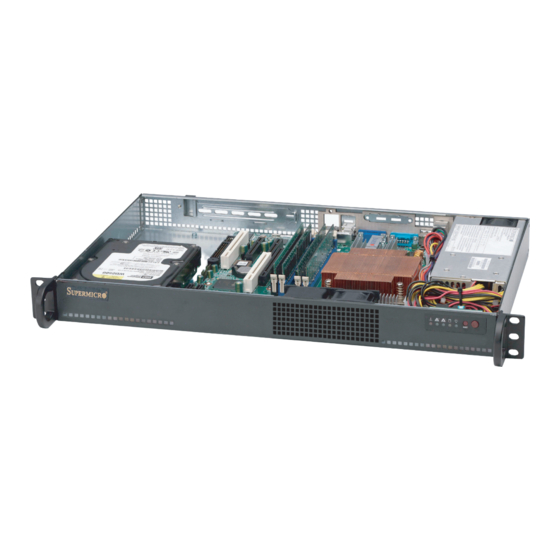
- Page 3 Preface Preface About This Manual This manual is written for professional system integrators and PC technicians. It provides information for the installation and use of the SC510 chassis. Installation and maintenance should be performed by experienced technicians only. Supermicro’s mini-sized SC510 1U chassis features a depth of only 11.3" with an advanced airflow and thermal design for client nodes, firewall applications, mail servers, Web servers and other server applications.
-
Page 4: Manual Organization
SC510 Chassis Manual Manual Organization Chapter 1 Introduction The first chapter provides an overview of the main components and features of the SC510 chassis. This chapter also includes contact information. Chapter 2 System Safety This section lists warnings, precautions, and system safety. It is recommended that you thoroughly familiarize yourself with this chassis safety precautions. -
Page 5: Table Of Contents
Preface Table of Contents Chapter 1 Introduction Overview ......................1-1 Shipping List ....................1-1 Part Numbers ....................1-1 Where to get Replacement Components ............1-2 Contacting Supermicro ..................1-3 Chapter 2 System Safety Overview ......................2-1 Warnings and Precautions ................2-1 Preparing for Setup .................. - Page 6 Installing the Air Shroud .................. 5-9 Checking the Server's Air Flow ..............5-10 System Fans ....................5-11 System Fans for the SC510-200B/203B and SC510L-200B ......5-11 The SC510(T)-203B Model System Fans ............. 5-13 Power Supply ....................5-14 Replacing the Power Supply ................. 5-14 Chapter 6 Rack Installation Overview ......................
-
Page 7: Chapter 1 Introduction
80%+ low-noise power supply. Shipping List Part Numbers Please visit the following link for the latest shiping lists and part numbers for your particular chassis model http://www.supermicro.com/ SC510-200B Chassis Power Model I/O Slots Supply 1x fixed 3.5"... -
Page 8: Where To Get Replacement Components
SC510 Chassis Manual Where to get Replacement Components Though not frequently, you may need replacement parts for your system. To en- sure the highest level of professional service and technical support, we strongly recommend purchasing exclusively from our Supermicro Authorized Distributors/ System Integrators/Resellers. -
Page 9: Contacting Supermicro
Chapter 1: Introduction Contacting Supermicro Headquarters Address: Super Micro Computer, Inc. 980 Rock Ave. San Jose, CA 95131 U.S.A. Tel: +1 (408) 503-8000 Fax: +1 (408) 503-8008 Email: marketing@supermicro.com (General Information) support@supermicro.com (Technical Support) Web Site: www.supermicro.com Europe Address: Super Micro Computer B.V. Het Sterrenbeeld 28, 5215 ML 's-Hertogenbosch, The Netherlands Tel:... - Page 10 SC510 Chassis Manual Notes...
-
Page 11: Chapter 2 System Safety
Chapter 2: System Safety Chapter 2 System Safety Overview This chapter provides a quick setup checklist to get your chassis up and running. Following the steps in order given should enable you to have your chassis set up and operational within a minimal amount of time. This quick setup assumes that you are an experienced technician, famailiar with common concepts and terminology. -
Page 12: Electrical Safety Precautions
SC510 Chassis Manual Electrical Safety Precautions Basic electrical safety precautions should be followed to protect yourself from harm and the SC510 from damage: • Be aware of the locations of the power on/off switch on the chassis as well as the room’s emergency power-off switch, disconnection switch or electrical outlet. -
Page 13: General Safety Precautions
Chapter 2: System Safety radiation exposure, do not open the enclosure or use the unit in any uncon- ventional way. General Safety Precautions • Keep the area around the chassis clean and free of clutter. • Place the chassis top cover and any system components that have been re- moved away from the system or on a table so that they won’t accidentally be stepped on. - Page 14 SC510 Chassis Manual • Do not let components or PCBs come into contact with your clothing, which may retain a charge even if you are wearing a wrist strap. • Handle a board by its edges only; do not touch its components, peripheral chips, memory modules or contacts.
-
Page 15: Chapter 3 Chassis Components
Chapter 3: Chassis Components Chapter 3 Chassis Components Overview This chapter describes the most common components included with your chassis. Some components listed may not be included or compatible with your particular chassis model. For more information, see the installation instructions detailed later in this manual. -
Page 16: Fans
SC510 Chassis Manual This chassis supports two system cooling fans in the SC510(L) models and three system cooling fans in the SC510T. All models have one power supply and come in black. Fans The SC510 chassis features two (three for SC510T) system fans. System fans for the SC510 chassis are powered from the serverboard. -
Page 17: Chapter 4 System Interface
Chapter 4: System Interface Chapter 4 System Interface Overview There are several LEDs on the control panel and on the drive carriers that provide system and component status. This chapter explains the meanings of all LED indi- cators and the appropriate responses that need to be taken. Figure 4-1. -
Page 18: Control Panel Buttons
SC510 Chassis Manual Control Panel Buttons The SC510 chassis includes two or three push-buttons located on the front panel: a reset button and a power on/off button • Reset: The reset button is used to reboot the system. • Power: The main power switch is used to apply or remove power from the power supply to the server system. - Page 19 Chapter 4: System Interface • NIC2: Indicates network activity on GLAN2 when flashing. • NIC1: Indicates network activity on GLAN1 when flashing. • HDD: Indicates IDE channel activity. SAS/SATA drive and/or DVD-ROM drive activity when flashing. • Power: Indicates power is being supplied to the system's power supply units. This LED should normally be illuminated when the system is operating.
-
Page 20: Drive Carrier Leds
SC510 Chassis Manual Drive Carrier LEDs Your chassis uses SAS/SATA drives. SAS/SATA Drives Each SAS/SATA drive carrier has two LEDs. • Green: Each Serial ATA drive carrier has a green LED. When illuminated, this green LED (on the front of the SATA drive carrier) indicates drive activity. A con- nection to the SATA backplane enables this LED to blink on and off when that particular drive is being accessed. -
Page 21: Power Supply Leds And Overheat Indicators
Chapter 4: System Interface Power Supply LEDs and Overheat Indicators • Solid Green: When illuminated, the green LED indicates that the power supply is on. • Solid Amber: When illuminated, the amber LED indicates the power supply is plugged in and turned off, or the system is off but in an abnormal state. •... -
Page 22: Overheating
SC510 Chassis Manual Overheating The section lists actions that should be taken in the unlikely event the server overheats. Overheat Temperature Setting Some backplanes allow the overheat temperature to be set at 45, 50, or 55 by changing a jumper setting. For more information, download the backplane user manual at www.supermicro.com. -
Page 23: Chapter 5 Chassis Setup And Maintenance
Chapter 5: Chassis Setup and Maintenance Chapter 5 Chassis Setup and Maintenance Overview This chapter covers the steps required to install components and perform mainte- nance on the chassis. The only tool you will need to install components and perform maintenance is a Phillips screwdriver. -
Page 24: Removing The Chassis Cover
SC510 Chassis Manual Removing the Chassis Cover R E V I S I O N S / -×- q DESCRIPTION LOCA ª©¥» ±Ô- z ¦ MODEL NO./ ¾÷«¬ : RANGE TOLERANCE BLEC ½ d³ò ¤½®t SC510 ¤j ˚ T¬ì§ÞªÑ¥÷¦³--¤½¥ X.xx ±... -
Page 25: Installing The Hard Drives
Chapter 5: Chassis Setup and Maintenance Installing the Hard Drives The 3.5" hard drive screws directly into the chassis Figure 5-2: Installing the 3.5" Hard Drive The 2.5" hard drives (1) must be installed in their brackets (2) before they are screwed into the chassis Figure 5-3: Installing the 2.5"... -
Page 26: Installing The Motherboard
SC510 Chassis Manual Installing the Motherboard Figure 5-4: Chassis Standoffs Permanent and Optional Standoffs Standoffs prevent short circuits by securing space between the motherboard and the chassis surface. The SC510 chassis includes permanent standoffs in locations used by most motherboards. These standoffs accept the rounded Phillips head screws included in the SC510 accessories packaging. -
Page 27: Installing The Motherboard:
Chapter 5: Chassis Setup and Maintenance Installing the Motherboard 1. Review the documentation that came with your motherboard. Become familiar with component placement, requirements, precautions, and cable connec- tions. 2. Open the chassis cover. 3. Compare the mounting holes in the chassis to those in the motherboard. Add or remove standoffs as needed. -
Page 28: Expansion Card/Expansion Slot Setup
SC510 Chassis Manual Expansion Card/Expansion Slot Setup SC510 chassis includes an I/O slot for the optional expansion card. A full-height, R E V I S I O N S / -×- q DESCRIPTION LOCATION DRAW ª©¥» ±Ô- z ¦ì¸ m -ק... - Page 29 Chapter 5: Chassis Setup and Maintenance 5. Insert the assembled expansion card and riser card into the expansion slot inside the chassis, carefully aligning the plate of the expansion card with the openings in the back of the chassis. 6. Replace the expansion card clip and screw it onto the chassis to hold the expansion card in place.
-
Page 30: Replacing The Heatsink
SC510 Chassis Manual Replacing the Heatsink The SC510 chassis includes a heatsink, which conducts heat away from the moth- erboard. 1. Unplug all power leading to the chassis. 2. Disconnect the wiring to the motherboard. 3. Remove the screws securing the motherboard to the chassis and lift it up and out of the chassis. -
Page 31: Installing The Air Shroud
Chapter 5: Chassis Setup and Maintenance Installing the Air Shroud Figure 5-9: Air Shroud for SC510 Chassis Air shrouds concentrate airflow to maximize fan efficiency. The SC510 chassis air shroud does not require screws to set it up. Place the air shroud in the chassis. The air shroud fits behind the fan closest to the power supply. -
Page 32: Checking The Server's Air Flow
SC510 Chassis Manual Checking the Server's Air Flow 1. Make sure there are no objects to obstruct airflow in and out of the server. 2. Use only recommended server parts. 3. Make sure no wires or foreign objects obstruct air flow through the chassis. Pull all excess cabling out of the airflow path, or use shorter cables. -
Page 33: System Fans
Chapter 5: Chassis Setup and Maintenance System Fans System Fans for the SC510-200B/203B and SC510L-200B Two heavy-duty fans within a single fan housing provide cooling for the chassis. These fans circulate air through the chassis as a means of lowering the chassis internal temperature. - Page 34 SC510 Chassis Manual Figure 5-11: Removing Fan Housing from Chassis 6. To remove the fans from the fan housing, gently push upwards on the fan from the underside of the fan housing. Gently ease the fan out of the top of the fan housing Figure 5-12: Removing Fans from Fan Housing 7.
-
Page 35: The Sc510(T)-203B Model System Fans
Chapter 5: Chassis Setup and Maintenance Fans Exchange Positions for Optimal Cooling Figure 5-13: SC510(T)-203B Only, Moving Fans for Optimal Cooling The SC510(T)-203B Model System Fans The SC510(T)-203B supports up to three system fans to provide optimal cooling for different motherboard designs. Users may move either of the two fans which are included with the SC510(T)-203B to the location where cooling is most beneficial to the system. -
Page 36: Power Supply
SC510 Chassis Manual Power Supply The SC510 chassis comes equipped with a 200 Watt power supply. This power supply is auto-switching capable. This enables it to automatically sense and operate at a 100v to 240v input voltage. The SC510 chassis has one power supply. In the unlikely event that the power supply unit fails, the system will shut down and you will need to change the power supply unit. - Page 37 Chapter 5: Chassis Setup and Maintenance 3. Remove the four screws which hold the power supply in the chassis. The two front mounting screws are located on the front of the power supply. The two rear mounting screws are accessed on the underside of the chassis and extend upwards through the mounting thru holes, to hold the power supply in place.
- Page 38 SC510 Chassis Manual Notes 5-16...
-
Page 39: Chapter 6 Rack Installation
Chapter 6: Rack Installation Chapter 6 Rack Installation Overview This chapter provides instructions for installing the chassis into a rack. Following these steps in the order given should enable you to have the system installed in a minimal amount of time. Unpacking the System You should inspect the box the chassis was shipped in, and note if it was damaged in any way. -
Page 40: Rack Precautions
SC510 Chassis Manual Warnings and Precautions! Rack Precautions • Ensure that the leveling jacks on the bottom of the rack are fully extended to the floor with the full weight of the rack resting on them. • In single rack installation, stabilizers should be attached to the rack. •... -
Page 41: Rack Mounting Considerations
Chapter 6: Rack Installation Rack Mounting Considerations Ambient Operating Temperature If installed in a closed or multi-unit rack assembly, the ambient operating tempera- ture of the rack environment may be greater than the ambient temperature of the room. Therefore, consideration should be given to installing the equipment in an environment compatible with the manufacturer’s maximum rated ambient tempera- ture (TMRA). -
Page 42: Rack Mounting Instructions
SC510 Chassis Manual Rack Mounting Instructions This section provides information on installing the SC510 chassis into a rack unit There are a variety of rack units on the market, which may mean the assembly procedure will differ slightly. You should also refer to the installation instructions that came with the rack unit you are using. -
Page 43: Appendix A Cables, Screws,And Other Accessories
Hard Drive Carrier (Tray): MCP-220-00044-0N 2.5" hard drive carrier. One carrier can hold up to two 2.5" hard drives. The SC510-200B can hold up to two 2.5" hard drive carriers, for a total of four hard drives. Figure A-1: Hard Driver Carrier... -
Page 44: Extending Power Cables
SC510 Chassis Manual Extending Power Cables Although Super Micro chassis are designed with to be efficient and cost-effective, some compatible motherboards have power connectors located in different areas. To use these motherboards you may have to extend the power cables to the mother boards. - Page 45 Appendix A: Chassis Cables A-4 Chassis Screws The accessory box includes all the screws needed to setup your chassis. This section lists and describes the most common screws used. Your chassis may not require all the parts listed. HARD DRIVE Flat head Pan head 6-32 x 5 mm...
- Page 46 SC510 Chassis Manual Notes...
-
Page 47: Appendix B Sc510 Power Supply Specifications
Appendix B: Power Supply Specifications Appendix B SC510 Power Supply Specifications This appendix lists power supply specifications for your chassis system. 200W (SC510-203B, SC510T-203B) MFR Part # PWS-203-1H 100 - 240V Rated AC Voltage 50 - 60Hz 4-2Amp +5V standby 2 Amp +12V 16 Amp +5V 8 Amp +3.3V 8 Amp... - Page 48 SC510 Chassis Manual 200W (SC510-200B, SC510T-200B) MFR Part # PWS-201-1H 100 - 240V Rated AC Voltage 50-60Hz 4-2 Amp Max +5V standby 2.0 Amp +12V 16.0 Amp +5V 8.0 Amp +3.3V 8.0 Amp -12V 0.5 Amp...
- Page 49 Appendix B: Power Supply Specifications Notes...
- Page 50 SC510 Chassis Manual Disclaimer (cont.) The products sold by Supermicro are not intended for and will not be used in life sup- port systems, medical equipment, nuclear facilities or systems, aircraft, aircraft devices, aircraft/emergency communication devices or other critical systems whose failure to per- form be reasonably expected to result in significant injury or loss of life or catastrophic property damage.