
Related Manuals for Canon IMAGERUNNER 2030 i


Summary of Contents for Canon IMAGERUNNER 2030 i
- Page 1 Reference Guide Reference Guide Read this guide first. Please read this guide before operating this product. After you finish reading this guide, store it in a safe place for future reference.
- Page 2 Ot¯ imageRUNNER 2030i/2025i/2022i/2018i Reference Guide...
-
Page 3: Manuals For The Machine
Manuals for the Machine The manuals for this machine are divided as follows. Please refer to them for detailed information. The manuals supplied with optional equipment are included in the list below. Depending on the system configuration and product purchased, some manuals may not be needed. Guides with this symbol are PDF manuals included on the Guides with this symbol are printed manuals. -
Page 4: How This Manual Is Organized
Relationship between Original Orientation and Preprinted Paper Output Chart, and index. Considerable effort has been made to ensure that this manual is free of inaccuracies and omissions. However, as we are constantly improving our products, if you need an exact specification, please contact Canon. -
Page 5: Table Of Contents
Contents Preface ............x How to Use This Manual . - Page 6 Parts and Their Functions ........1-11 External View .
- Page 7 Chapter 3 Optional Equipment System Configuration ..........3-2 Optional Equipment .
- Page 8 Output Tray Designation ........4-39 Standard Paper for the Stack Bypass .
-
Page 9: Detecting And Installing Drivers That Support Functions Specified On
Clearing Page Totals ......... . .6-25 Accepting Print and Scan Jobs with Unknown IDs . - Page 10 Service Call Message ..........8-47 Contacting Your Local Authorized Canon Dealer ..... 8-47...
-
Page 11: Preface
Preface Thank you for purchasing the Canon imageRUNNER 2030i/2025i/2022i/2018i. Please read this manual thoroughly before operating the machine to familiarize yourself with its capabilities, and to make the most of its many functions. After reading this manual, store it in a safe place for future reference. -
Page 12: Keys Used In This Manual
Keys Used in This Manual The following symbols and key names are a few examples of how keys to be pressed are expressed in this manual: • Touch Panel Display Keys: [Key Name] Examples: [Cancel] [Done] • Control Panel Keys: Key icon (Key Name) Examples: (Start) -
Page 13: Illustrations Used In This Manual
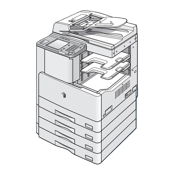
Illustrations Used in This Manual Illustrations used in this manual are those displayed when the imageRUNNER 2030i has the following optional equipment attached to it: the Finisher-U2, Additional Finisher Tray-C1, and Cassette Feeding Module-Q1. -
Page 14: Operations And Terms Used In This Manual
Operations and Terms Used in This Manual This machine makes effective use of memory to perform print operations efficiently. For example, as soon as the machine has scanned the original that you want to copy, it can immediately scan the next person’s original. You can also print from this machine, using a function other than the Copy function. - Page 15 Printing Outputting documents such as a copy, fax, or outputting data sent from a personal computer to the machine. Copying Printing data scanned from an original, followed by finishing options, such as stapling.
-
Page 16: Legal Notices
Legal Notices FCC (Federal Communications Commission) imageRUNNER 2030i/2025i/2022i/2018i: Model F189800 This device complies with Part 15 of the FCC Rules. Operation is subject to the following two conditions: This device may not cause harmful interference, this device must accept any interference received, including interference that may cause undesired operation. -
Page 17: Laser Safety
If your equipment malfunctions, please contact your local authorized Canon dealer from whom you purchased the equipment (if under warranty), or with whom you have a servicing contact. If you are not sure who to contact, and have both purchased and are using the equipment in the U.S.A., please refer to the “SUPPORT”... -
Page 18: International Energy Star Program
IPv6 Forum. Trademarks Canon, the Canon logo, imageRUNNER, and NetSpot are registered trademarks of Canon Inc. in the United States and may also be trademarks or registered trademarks in other countries. Adobe and Adobe Acrobat are trademarks of Adobe Systems Incorporated. -
Page 19: Copyright
Disclaimers The information in this document is subject to change without notice. CANON INC. MAKES NO WARRANTY OF ANY KIND WITH REGARD TO THIS MATERIAL, EITHER EXPRESS OR IMPLIED, EXCEPT AS PROVIDED HEREIN, INCLUDING WITHOUT LIMITATION, THEREOF, WARRANTIES AS TO MARKETABILITY, MERCHANTABILITY, FITNESS FOR A PARTICULAR PURPOSE OF USE OR NON-INFRINGEMENT. -
Page 20: Legal Limitations On The Usage Of Your Product And The Use Of Images
Legal Limitations on the Usage of Your Product and the Use of Images Using your product to scan, print or otherwise reproduce certain documents, and the use of such images as scanned, printed or otherwise reproduced by your product, may be prohibited by law and may result in criminal and/or civil liability. A non-exhaustive list of these documents is set forth below. -
Page 21: Important Safety Instructions
If these items are dropped or spilled inside the machine, immediately turn OFF the main power switch, and disconnect the power cord from the power outlet. Then, contact your local authorized Canon dealer. - Necklaces and other metal objects - Cups, vases, flowerpots, and other containers filled with water or liquids... -
Page 22: Power Supply
CAUTION • Do not install the machine in unstable locations, such as on unsteady platforms or inclined floors, or in locations subject to excessive vibrations, as this may cause the machine to fall or tip over, resulting in personal injury. •... -
Page 23: Handling
If the machine makes strange noises, or gives off smoke, heat, or strange smells, immediately turn OFF the main power switch, and disconnect the power cord from the power outlet. Then, contact your local authorized Canon dealer. Continued use of the machine in this condition may result in a fire or electrical shock. - Page 24 CAUTION • Do not place heavy objects on the machine, as they may tip over and fall resulting in personal injury. • Close the feeder gently to avoid catching your hands, as this may result in personal injury. • Do not press down hard on the feeder when using the platen glass to make copies of thick books.
-
Page 25: Maintenance And Inspections
• The laser beam can be harmful to human bodies. Since radiation emitted inside the product is completely confined within protective housings and external covers, the laser beam cannot escape from the machine during any phase of user operation. Read the following remarks and instructions for safety. •... - Page 26 CAUTION • The fixing unit, the duplex unit, and their surroundings inside the machine may become hot during use. When removing jammed paper or when inspecting the inside of the machine, do not touch the fixing unit, the duplex unit, and their surroundings, as doing so may result in burns.
-
Page 27: Consumables
Consumables WARNING • Do not burn or throw used toner cartridges into open flames, as this may cause the toner remaining inside the cartridges to ignite, resulting in burns or a fire. • Do not store toner cartridges or copy paper in places exposed to open flames, as this may cause the toner or paper to ignite, resulting in burns or a fire. -
Page 28: Before You Start Using This Machine
Before You Start Using This Machine CHAPTER This chapter describes what you should know before using this machine, such as parts and their functions, and how to turn ON the main power. Installation Location and Handling ......... . 1-2 Installation Precautions . -
Page 29: Installation Location And Handling
Installation Location and Handling This section describes precautions for installation location and handling. We recommend that you read this section prior to using this machine. Installation Precautions Avoid Installing the Machine in the Following Locations ■ Avoid locations subject to temperature and humidity extremes, whether low or high. - Page 30 ■ Avoid poorly ventilated locations. This machine generates a slight amount of ozone during normal use. Although sensitivity to ozone may vary, this amount is not harmful. Ozone may be more noticeable during extended use or long production runs, especially in poorly ventilated rooms. It is recommended that the room be appropriately ventilated, sufficient to maintain a comfortable working environment, in areas of machine operation.
- Page 31 ■ Avoid locations that are subject to vibration. For example, avoid installing the machine on unstable floors or stands. ■ Avoid exposing the machine to rapid changes in temperature. If the room in which the machine is installed is cold but rapidly heated, water droplets (condensation) may form inside the machine.
-
Page 32: Select A Safe Power Supply
Select a Safe Power Supply ■ Plug the machine into a standard 120 V AC, three-wire grounded outlet. ■ Make sure that the power supply for the machine is safe, and has a steady voltage. ■ Do not connect other electrical equipment to the same power outlet to which the machine is connected. -
Page 33: Provide Adequate Installation Space
Provide Adequate Installation Space ■ Provide enough space on each side of the machine for unrestricted operation. The optional Finisher-U2 and Document Tray-J1 are attached 4" (100 mm) or more 49 1/4" (1,249 mm) 47 1/8" (1,198 mm) 49 1/8" (1,247 mm) * * The width is 40"... -
Page 34: Moving The Machine
■ If you intend to move the machine, even to a location on the same floor of your building, contact your local authorized Canon dealer beforehand. ■ The machine is heavy, and requires two or more people to lift it. Therefore, do not attempt to move it by yourself. -
Page 35: Handling Precautions
Handling Precautions ■ Some parts inside the machine are subject to high-voltage and temperatures. Take adequate precautions when inspecting the inside of the machine. Do not carry out any inspections not described in this manual. ■ Do not attempt to disassemble or modify the machine. ■... - Page 36 ■ If there is smoke or unusual noise, immediately turn the main power switch OFF, disconnect the power cord from the power outlet, and then call your local authorized Canon dealer. Using the machine in this state may cause a fire or electrical shock. Also, avoid placing objects around the power plug so that the machine can be disconnected whenever necessary.
- Page 37 ■ This machine generates a slight amount of ozone during normal use. Although sensitivity to ozone may vary, this amount is not harmful. Ozone may be more noticeable during extended use or long production runs, especially in poorly ventilated rooms. It is recommended that the room be appropriately ventilated, sufficient to maintain a comfortable working environment, in areas of machine operation.
-
Page 38: Parts And Their Functions
Parts and Their Functions This section provides you with the names and functions of all the parts on the outside and inside of the main unit, feeder, control panel, and touch panel display. An illustration of the machine with some optional equipment attached to it is also provided. - Page 39 a Stack Bypass d Main Power Switch Use the stack bypass to feed paper manually Press to the “I” side to turn the power ON. (See and for loading nonstandard paper stock, such “Main Power and Control Panel Power,” on as envelopes.
-
Page 40: Feeder Parts And Functions
Feeder Parts and Functions CAUTION Do not insert your fingers into the gaps around the original supply tray, as your fingers may get caught. Also, be careful not to drop objects, such as paper clips into the gaps, as doing so may cause damage to the machine or cause it to break down. -
Page 41: Internal View
Internal View The imageRUNNER 2018i with the optional Cassette Feeding Module-P1 and Cassette Feeding Module-Q1 attached. a Platen Glass e Paper Drawer’s Left Covers Place originals here when scanning books, thick Open these covers to clear paper jams in Paper originals, thin originals, transparencies, etc. -
Page 42: Control Panel Parts And Functions
When the Error indicator d Reset key maintains a steady red light, contact your local Press to restore the standard settings of the authorized Canon dealer. machine. m Log In/Out key e Numeric keys Press when setting or enabling Department ID Press to enter numerical values. -
Page 43: Main Power And Control Panel Power
Main Power and Control Panel Power The machine is provided with two power switches, a main power switch and a control panel power switch. How to Turn ON the Main Power This section explains how to turn ON the main power. Make sure that the power plug is firmly inserted into the power outlet. - Page 44 The screen shown below is displayed while the system software is loading. The Start Up screen is displayed until the machine is ready to scan. If a message is displayed on the touch panel display, proceed to step 4. The machine is ready to scan in approximately eight seconds (at a room temperature of 68°F) after the screen above appears.
- Page 45 NOTE • Once the message <Ready to copy.> appears on the touch panel display, you can specify settings. Copying or printing begins automatically, as soon as the machine finishes warming up. (See Chapter 1, “Introduction to Copying,” in the Copying Guide.) •...
- Page 46 NOTE • If the optional Card Reader-E1 is not attached, this message will not appear. • For instructions on using the optional Card Reader-E1, see “Card Reader-E1,” on p. 3-14. ● If the message <Enter the Department ID and Password using the numeric keys.>...
- Page 47 ON and the optional Cassette Heater Unit-34 is connected. For details about the optional Cassette Heater Unit-34, contact your local authorized Canon dealer. NOTE For instructions on entering the User ID and password on the User ID Management screen, see “Entering a User ID and Password,”...
-
Page 48: Control Panel Power Switch
Control Panel Power Switch To turn the control panel ON or OFF, press the control panel power switch. When turned OFF, the machine is in the Sleep mode. Control Panel Power Switch Machine Status Standby mode (ready for immediate copying or printing) Sleep mode NOTE •... -
Page 49: System Settings
System Settings It is necessary to set up the machine before using it on a network, as a printer, or with the Send or optional Fax function. To set up the machine, refer to the following guides or sections for instructions: ■... -
Page 50: Obtaining And Registering A License Key
A license key can be obtained by using a web browser to access the license management system. Access the system by entering the following URL: http://www.canon.com/lms/license/ ■ Administration Numbers That Are Necessary to Obtain a License Key Follow the procedure displayed on the screen. The following administration numbers are necessary to obtain the license key: •... -
Page 51: Registering A License Key
Registering a License Key You need to register a license key in your machine to activate the bar code printing function. (Additional Functions) ➞ [System Settings]. Press Press [▼] or [▲] until [License Registration] appears ➞ press [License Registration]. 1-24 Obtaining and Registering a License Key... - Page 52 (numeric keys) ➞ press Enter the license key using [Start]. Details of each item are shown below. Press to move the position of the cursor. [ ] [ ]: [Backspace]: Press to delete the last number entered. If the following screen is displayed, press [OK] ➞ enter the correct license key. 1-25 Obtaining and Registering a License Key...
- Page 53 If the following screen is displayed, the license key cannot be registered. Press [OK], and then cancel the registration. Check if the required option or function is properly installed in the machine. The message <Installation was successful.> appears. License registration is complete. Press [OK].
-
Page 54: Basic Operations
Basic Operations CHAPTER This chapter describes the main features and basic operations of the machine. What This Machine Can Do ..........2-2 Overview of the imageRUNNER 2030i/2025i/2022i/2018i . -
Page 55: What This Machine Can Do
What This Machine Can Do All the elements you will ever need in a digital multitasking machine. The imageRUNNER 2030i/2025i/2022i/ Copy 2018i incorporates a rich array of input and output features that can greatly enhance Print Send your efficiency. Equipped with features that meet the needs of document work in a digitized environment, the imageRUNNER 2030i/ Scan... -
Page 56: Network Interface
Remote UI, NetSpot*, etc. NetSpot enables you to manage and make various settings for the printers and copiers connected to a network from a PC. * NetSpot can be downloaded from Canon’s Web site (http://www.usa.canon.com). Manage What This Machine Can Do... -
Page 57: Network Scanning
Using the Remote User Interface See the Remote UI Guide You can control functions, such as confirming the status of the machine, job operations, and printing instructions, all from your PC’s Web browser. Browser The imageRUNNER 2030i/2025i/2022i/ 2018i comes standard equipped with a direct Ethernet connection interface. -
Page 58: Overview Of The Imagerunner 2030I/2025I/2022I/2018I
Overview of the imageRUNNER 2030i/2025i/2022i/2018i Most operations on this machine are executed from the touch panel display. By pressing the keys according to the instructions on the touch panel display, you can utilize the functions of this machine efficiently. CAUTION Press the touch panel display keys gently with your fingers. -
Page 59: User Management And Restriction
■ Keys Displayed on the Touch Panel Display The Copy Basic Features screen is shown as an example below. a Job/Print Status Display Area b System Monitor The progress of jobs and copy operations, Press this key to check or cancel jobs, and the status of devices and and to check the job log. -
Page 60: Specifying Settings
Specifying Settings The Additional Functions screen appears when you press (Additional Functions). The Additional Functions screen enables you to make common settings related to many functions of the machine, as well as customize specific functions to suit your needs. For more information on the settings not explained in this manual, see the following manuals: •... -
Page 61: Using The Sleep Mode To Conserve Power
NOTE • Settings made from the Additional Functions screen are not changed even if you press (Reset). • For instructions on customizing settings, see Chapter 4, “Customizing Settings.” • For instructions on specifying System Settings, see Chapter 6, “System Manager Settings.”... -
Page 62: Checking And Canceling Print Jobs
Checking and Canceling Print Jobs The System Monitor screen enables you to check the status of the machine or cancel print jobs. The System Monitor Screen (Print) The System Monitor Screen (Device Status) Overview of the imageRUNNER 2030i/2025i/2022i/2018i... - Page 63 NOTE • For instructions on checking the status of Copy, Fax, and Send jobs, see Chapter 5, “Checking Job and Device Status,” in this manual, and Chapter 7, “Checking/Changing the Send/Receive Status,” in the Sending and Facsimile Guide. • The icons that appear in the Job/Print Status Display Area (on the bottom left of the screen) are described below.
-
Page 64: Other Useful Functions
Other Useful Functions Other useful functions include: ■ Auto Drawer Switching If a paper drawer runs out of paper during printing, the machine automatically locates another paper drawer loaded with the same size paper, and begins feeding paper from that paper drawer. NOTE •... -
Page 65: Paper Supply Indicator
■ Paper Supply Indicator The paper supply indicator shows whether paper is loaded in each paper drawer. appears on the Paper Select screen when paper is loaded in a paper drawer. blinks on the screen that appears when paper in a paper drawer has run out during printing. (See Chapter 2, “Basic Copying Features,”... -
Page 66: Using The Touch Panel Display
Using the Touch Panel Display This section describes the keys that are frequently used on the touch panel display. Information on how to adjust the brightness of the touch panel display is also provided. CAUTION Press the touch panel display keys gently with your fingers. Do not press the touch panel display with a pencil, ballpoint pen, or other sharp objects that can scratch the surface of the touch panel display or break it. -
Page 67: Touch Panel Key Display
Touch Panel Key Display When you press a key on the touch panel display, that key is highlighted, and the corresponding mode is set. When you set certain modes, the characters on some keys may become grayed out. You cannot press keys that are grayed out. This means that you cannot set these modes in combination with the presently set mode. -
Page 68: Numeric Keys
Keys that have a solid square ( ) in the lower right corner and that appear on screens for storing settings, are keys that already have settings stored in them. Settings Are Stored No Settings Are Stored ■ Keys That Display a Drop-Down List Pressing a key that has a right triangle ( ) to the right of the name of the selection, displays a drop-down list containing other setting options. -
Page 69: Adjusting The Brightness
Adjusting the Brightness If the touch panel display is difficult to view, use the display contrast dial on the control panel to adjust its brightness. Display Contrast Lighter Darker NOTE To make the touch panel display brighter, turn the dial counterclockwise. To make it darker, turn the dial clockwise. -
Page 70: Entering Characters From The Touch Panel Display
For screens that require alphanumeric entries, enter characters using the keys displayed on the touch panel display, as shown below. Alphanumeric Characters Example: Enter <Canon>. To enter alphanumeric characters, make sure that <Alphabet> is displayed above [Entry Mode]. Press [Entry Mode] to switch between <Alphabet> and <Other>. - Page 71 Enter <Canon>. To enter uppercase letters, press [Shift]. To enter a space, press [Space]. To move the cursor, press [ ] or [ ]. To enter symbols, press [Entry Mode] ➞ select [Other] ➞ enter the desired symbols. The characters you entered are displayed, as shown below.
-
Page 72: Symbols
Symbols Example: Enter <é>. Press [Entry Mode] ➞ select [Other]. Press [Entry Mode] to switch between <Alphabet> and <Other>. Press [▼] or [▲] to display the symbol that you want to enter. 2-19 Entering Characters from the Touch Panel Display... - Page 73 Press [é]. To enter a space, press [Space]. To move the cursor, press [ ] or [ ]. To enter alphanumeric characters, press [Entry Mode] ➞ select [Alphabet] ➞ enter the desired characters. The characters you entered are displayed, as shown below. NOTE •...
-
Page 74: Values In Inches
Values in Inches If you want to enter values in inches in all modes which require a numeric entry, set Inch Entry to ‘On’ in Common Settings (from the Additional Functions screen). (See “Inch Entry,” on p. 4-28.) This enables you to enter values in inches when you press [Inch] on a screen requiring a numeric entry or measurement. -
Page 75: Entering The Department Id And Password
Entering the Department ID and Password If Department ID Management has been set, the Department ID and password must be entered before using this machine. NOTE • For instructions on setting the Department ID and password, see “Department ID Management,” on p. 6-6. •... - Page 76 NOTE If you make a mistake when entering the Department ID or password, press (Clear) ➞ enter the correct values. Press (Log In/Out). The Basic Features screen of the selected function appears on the touch panel display. NOTE • If using Department ID Management, the Department ID and message <After using the machine, press the ID key.>...
-
Page 77: The Control Panel
When your operations are complete, press (Log In/Out) on the control panel. If you are using a control card, remove the control card, and take it with you. (See “Card Reader-E1,” on p. 3-14.) The screen for entering the Department ID and password appears. NOTE •... -
Page 78: Entering A User Id And Password
Entering a User ID and Password If User ID Management in System Settings (from the Additional Functions screen) is set to ‘On’, and User IDs and passwords are registered in the machine, you must enter a User ID and password before using this machine. IMPORTANT User IDs and passwords must be registered in the machine from the Remote UI beforehand. - Page 79 Enter your User ID (up to 32 characters) ➞ press [OK]. You can also enter the User ID using (numeric keys). Press [Password]. 2-26 Entering a User ID and Password...
- Page 80 Enter the password (up to 32 characters) ➞ press [OK]. You can also enter the password using (numeric keys). Press (Log In/Out). The Basic Features screen of the selected function appears on the touch panel display. NOTE If the User ID or password that you entered is incorrect, the message <This number has not been registered.
- Page 81 When your operations are complete, press (Log In/Out) on the control panel. The screen for entering the User ID and password appears. NOTE • To perform operations again, you have to re-enter your User ID and password. • If you do not press (Log In/Out) after you are finished operating the machine, any subsequent copies and scans for Send/Fax functions made are added to the total of the User ID you previously entered.
-
Page 82: Making Prints Using The Stack Bypass
Making Prints Using the Stack Bypass If you are making prints on labels, transparencies, or nonstandard paper size stock, load the paper stock into the stack bypass. IMPORTANT • Note the following points when using the stack bypass: - Paper Quantity: one to approximately 80 sheets (22 lb bond (80 g/m ), stack approximately 1/4"... - Page 83 NOTE • Envelopes may be creased in the printing process. • For high-quality printouts, use paper recommended by Canon. • For more information on paper types that can be used with this machine, see “Available Paper Stock,” on p. 2-44.
- Page 84 NOTE If the paper size you are going to load into the stack bypass is different from the paper size stored in Stack Bypass Standard Settings, set Stack Bypass Standard Settings to ‘Off’ in Common Settings (from the Additional Functions screen). (See “Standard Paper for the Stack Bypass,”...
- Page 85 Load the paper into the stack bypass. ❑ Make sure that the height of the paper stack does not exceed the loading limit mark ( ❑ When you use the stack bypass to make copies, straighten out curled paper prior to use, as shown below. Curled paper may cause a paper jam. Feeding Direction ❑...
- Page 86 ❑ To print on the back side of preprinted paper, load the preprinted paper face up into the stack bypass, as shown in the illustration below. Feeding Direction The screen for selecting the paper size appears. IMPORTANT • When loading paper into the stack bypass, align the paper stack neatly between the slide guides.
- Page 87 ● If you are loading envelopes into the stack bypass: ❑ Take five envelopes, loosen them as shown, and then stack them together. Repeat this step five times for each set of five envelopes. ❑ Place the envelopes on a clean, level surface, and press all the way around the envelopes by hand, in the direction of the arrows, to remove any curls.
- Page 88 ❑ Hold down the four corners of the envelopes firmly, so that they and the sealed or glued portion stay flat. Flap IMPORTANT • Do not print on the back side of the envelopes (the side with the flap). • If the envelopes become filled with air, flatten them by hand before loading them into the stack bypass.
- Page 89 IMPORTANT • The stack bypass can hold 10 envelopes at a time. • Envelopes may be creased in the printing process. Select the desired paper size. NOTE The paper size/type setting in the [Stack Bypass] setting screen is available if Stack Bypass Standard Settings is set to ‘Off’...
- Page 90 ❑ Select the desired paper type ➞ press [OK]. IMPORTANT When printing on special types of paper, such as heavyweight paper or transparencies, be sure to correctly set the paper type, especially if you are using heavyweight paper. If the type of paper is not set correctly, it could adversely affect the quality of the image.
- Page 91 ❑ Press [X] to specify the horizontal axis of the paper ➞ enter a value. ❑ Press [Y] to specify the vertical axis of the paper size ➞ enter a value. ❑ Press [OK]. The display returns to the paper size selection screen. NOTE •...
- Page 92 ❑ Press [Next]. ❑ Select the desired paper type ➞ press [OK]. IMPORTANT • When printing on special types of paper, such as heavyweight paper, be sure to correctly set the paper type, especially if you are using heavyweight paper. If the type of paper is not set correctly, it could adversely affect the quality of the image.
- Page 93 ❑ Select the envelope type ➞ press [OK]. The display returns to the paper size selection screen. IMPORTANT • If the envelope type is not selected correctly, a paper jam may occur. • If you select [Envelope], you cannot use the finishing modes, 1 2-Sided, 2 2-Sided, Book 2-Sided, 2-Page Separation, or Image Combination mode.
- Page 94 The display returns to the Copy Basic Features screen, and the selected paper size and type are displayed. If the Copy function is selected, place your originals ➞ select the desired copy settings. Press (Start). Copying starts. NOTE To cancel all settings and return the machine to the Basic Features screen, press (Reset).
-
Page 95: Multifunctional Operations
Multifunctional Operations The imageRUNNER 2030i/2025i/2022i/2018i offers the user many functions, such as printing, scanning, copying, and sending, which can be used together. The following tables provide you with the details of multifunctional operations. ■ How to read the tables The tables below indicate the availability of the operations listed in the vertical columns when the operations listed in the horizontal rows are already being performed. - Page 96 : Available : Unavailable : Available, but with conditions Send Current Jobs Auto RX Direct Memory Memory Document Scanning Printing Next Jobs Copy Scanning Direct TX Memory TX Send Memory RX Auto RX Document Printing Receiving Data Printer Printing NOTE The machine’s performance may be affected if several network send and receive jobs are being carried out at the same time.
-
Page 97: Available Paper Stock
Available Paper Stock The paper types that can be used with this machine are shown in the following table. Icons indicating the type of paper loaded in each paper drawer can be displayed on the paper selection screen if you store that information in the machine beforehand. - Page 98 : Available : Unavailable Paper Source Paper Paper Paper Size Width x Length Stack Drawer Drawer Bypass 1, 2 3, 4 11" x 17" 11" x 17" 8 1/2" x 14" 8 1/2" x 11" LTRR 11" x 8 1/2" STMT 8 1/2"...
- Page 99 2-46 Available Paper Stock...
- Page 100 Optional Equipment CHAPTER This chapter describes the uses of optional equipment, and their special functions. System Configuration ........... . 3-2 Optional Equipment .
-
Page 101: Optional Equipment
System Configuration This section provides you with illustrations of all the optional equipment that can be attached to the machine, and shows you examples of different system configurations. Optional Equipment System Configuration... - Page 102 a Inner 2 Way Tray-E2 d Document Tray-J1 Attaching the Inner 2 Way Tray-E2 enables you Located on the top right side of the machine. It to have two output trays. can be used for originals that are waiting to be scanned, or have already been scanned.
-
Page 103: Sample System Configurations
The Super G3 FAX Board enables you to fax documents that have been created in applications directly from your computer. NOTE The Canon Fax Driver is supplied with the Super G3 FAX Board, and enables you to send fax images from a computer via the machine. System Configuration... -
Page 104: Available Combination Of Options
Available Combination of Options The table shown below describes the optional equipment that is needed to use each function, the available combination of options that can be installed simultaneously, and the limitations when installing optional equipment. Simultaneous Installation Optional Equipment Machine Function Needed Required... -
Page 105: Cassette Feeding Module-P1/Q1
Cassette Feeding Module-P1/Q1 If you attach the Cassette Feeding Module-P1 (available only for the imageRUNNER 2018i), you have one additional paper source for print jobs. If you attach the Cassette Feeding Module-Q1 to the machine, you have two additional paper sources for print jobs. Each cassette holds up to 250 sheets (22 lb bond (80 g/m )) of 11"... -
Page 106: Optional Accessory
Optional Accessory ■ FL Cassette-AF1 This cassette can be adjusted to hold various paper sizes. (See “Adjusting a Paper Drawer to Hold a Different Paper Size,” on p. 7-8.) • Available Locations: Paper Drawers 1, 2, 3, or 4 • Available Paper Sizes: 11"... -
Page 107: Finisher-U2
Finisher-U2 The Finisher-U2 is equipped with the following finishing modes: Collate, Group, Offset, and Staple. (See “Finishing Modes,” on p. 3-9.) If the optional Additional Finisher Tray-C1 is attached to the Finisher-U2, prints can be delivered to two different locations. IMPORTANT The Finisher-U2 cannot be attached with the optional Inner 2 Way Tray-E2. -
Page 108: Finishing Modes
Finishing Modes The Finisher-U2 is equipped with the following finishing modes. CAUTION • Do not place anything other than output paper in the trays of the finisher, as this may damage the trays. • Do not place anything under the trays of the finisher, as this may damage the trays. - Page 109 ■ Offset Mode The print output is shifted alternately to the front and back of the tray, in a vertical (portrait) orientation, or a horizontal (landscape) orientation, depending on the orientation of your originals. For example, if you place LTRR originals, the paper is output and shifted in the horizontal direction.
- Page 110 CAUTION Do not place your hand in the roller or the part of the tray where stapling is performed if the finisher is attached, as this may result in personal injury. IMPORTANT • If the Staple mode is set, the output trays move downward as the stack of paper that is output increases in quantity and thickness.
-
Page 111: Inner 2 Way Tray-E2
Inner 2 Way Tray-E2 If you attach the Inner 2 Way Tray-E2 to the machine, prints can be delivered to both the main tray and the Inner 2 Way Tray-E2. When the Inner 2 Way Tray-E2 is attached to the machine, the following finishing modes are available. -
Page 112: Parts And Their Functions
Parts and Their Functions a Inner 2 Way Tray-E2 (Tray B) b Main Output Tray (Tray A) Prints are output to this tray. Prints are output to this tray. 3-13 Inner 2 Way Tray-E2... -
Page 113: Card Reader-E1
Card Reader-E1 If the Card Reader-E1 is attached to the machine, you must insert a control card to operate it. The Card Reader-E1 performs Department ID Management automatically. IMPORTANT If User ID Management in System Settings (from the Additional Functions screen) is set to ‘On’, manually enter your card number in the card ID field. -
Page 114: Procedure Before Using The Machine
Procedure before Using the Machine Insert the control card into the card slot, making sure that it is facing in the correct direction. The Basic Features screen of the selected function appears on the touch panel display. 3-15 Card Reader-E1... -
Page 115: Procedure After Using The Machine
Procedure after Using the Machine After you finish using the machine, remove the control card. The touch panel display returns to the screen for inserting the control card. IMPORTANT • Once you have removed the control card, you cannot operate the machine until the control card is inserted again. -
Page 116: Department Id Management
Department ID Management This section describes how to change the password and page limit, and how to check the print totals when a control card is being used. IMPORTANT Do not change the password when using a control card. The control card will become unusable if the password for the Department ID is changed. - Page 117 Press [Department ID Management]. NOTE If the desired setting is not displayed, press [▼] or [▲] to scroll to the desired setting. Press [Register ID/Password]. 3-18 Card Reader-E1...
- Page 118 Press [▼] or [▲] to display the Department ID whose password you want to change ➞ select the Department ID ➞ press [Edit]. NOTE Press and hold down [▼] or [▲] to quickly and continuously scroll through the available Department ID pages. Continuous scrolling is useful when a large number of Department IDs are registered.
- Page 119 NOTE • If you make a mistake when entering the password, press (Clear) to clear the password ➞ enter the correct password. • You cannot change the Department ID. If you want to change or set a page limit restriction, press [Turn Limits On/Off and Set Page Limits].
- Page 120 Press [ ] (Page Limit) next to [On]/[Off] of the desired function(s) ➞ enter the page limit restriction using (numeric keys). IMPORTANT • The machine stops scanning if any one of the Scan Limits are reached while the machine is scanning originals that are being fed from the feeder. (Those originals that were scanned before the limit is reached are not added to the scan count.) •...
- Page 121 Press [OK] ➞ [OK]. The page limits for the selected functions are set. Press [Done]. 3-22 Card Reader-E1...
- Page 122 Press [OK]. 3-23 Card Reader-E1...
- Page 123 Press [Done] repeatedly until the Basic Features screen appears. Copy Basic Features Screen Send Basic Features Screen Network Scan Function Screen 3-24 Card Reader-E1...
-
Page 124: Checking The Page Counts On A Control Card
Checking the Page Counts on a Control Card You can check the page counts on the control card you are currently using. Press [System Monitor]. Press [Device] ➞ [Pg Ct Chk]. 3-25 Card Reader-E1... -
Page 125: Checking And Printing Counter Information
Check the page counts ➞ press [Done] ➞ [Done]. The display returns to the Basic Features screen. Checking and Printing Counter Information You can display and print a list of how much paper was used by each department. (Additional Functions) ➞ [System Settings] ➞ Press [Department ID Management]. - Page 126 Press [Page Totals]. Check or print the page total count. The page totals that belong to print jobs without a Department ID (left blank) are the number of prints from computers that do not correspond with a registered Department ID. These prints are referred to as prints with unknown IDs. The scan page totals that belong to scan jobs without a Department ID (left blank) are the number of pages that have been scanned from computers that do not correspond with a registered Department ID.
- Page 127 NOTE Press and hold down [▼] or [▲] to quickly and continuously scroll through the available Department ID pages. Continuous scrolling is useful when a large number of Department IDs are registered. ● If you want to print the displayed list: ❑...
- Page 128 ❑ Press [Yes]. If you do not want to print the displayed list, press [No]. Printing starts. The screen below is displayed while the machine is printing the counter information. NOTE • To cancel printing, press [Cancel]. • To close the screen that is displayed while the machine is printing the Page Count List, press [Done].
- Page 129 Press [Done]. Press [OK]. 3-30 Card Reader-E1...
-
Page 130: Clearing Page Totals
Clearing Page Totals You can clear the page totals made for all departments or for specific departments. (Additional Functions) ➞ [System Settings] ➞ Press [Department ID Management]. If necessary, see the screen shots in steps 1 and 2 of “Changing the Password and Page Limit,”... - Page 131 Press [Yes]. If you do not want to clear the page totals, press [No]. The message <Erased.> appears for approximately two seconds on the touch panel display. The page totals are cleared. 3-32 Card Reader-E1...
- Page 132 Press [Done]. Press [OK]. 3-33 Card Reader-E1...
-
Page 133: Accepting Print And Scan Jobs With Unknown Ids
Accepting Print and Scan Jobs with Unknown IDs You can specify whether to accept or reject print and network scan jobs from computers that do not correspond with a registered Department ID. NOTE The default setting is ‘On’ for both <Allow ID Unknown Printer Jobs> and <Allow ID Unknown Remote Scan Jobs>. - Page 134 Allow ID Unknown Remote Scan Jobs: [On]: The machine accepts remote scan jobs from computers that do not correspond with a registered Department ID. [Off]: The machine does not accept remote scan jobs from computers that do not correspond with a registered Department ID. Press [Done] repeatedly until the Basic Features screen appears.
- Page 135 3-36 Card Reader-E1...
-
Page 136: Customizing Settings
Customizing Settings CHAPTER This chapter explains how to change the machine’s Common Settings and Timer Settings, and customize them to suit your needs. What Are Additional Functions? ..........4-3 Accessing the Additional Functions Screen . - Page 137 4. Customizing Settings Preventing Paper Curls Due to Paper Type (Special Mode P) ............4-76 Setting the Bond Special Fixing Mode .
-
Page 138: What Are Additional Functions
What Are Additional Functions? Additional Functions enable you to customize the machine’s various settings. IMPORTANT • When User ID Management is set to ‘On’, users whose user type is registered as “User” (end user) cannot change the System Manager Settings even if there are no System Manager ID and System Password set. - Page 139 Press a mode key to specify its settings. For an overview of all the settings you can change from the Additional Functions screen, see “Additional Functions Settings Table,” on p. 4-5. NOTE The Common Settings, Adjustment/Cleaning, and System Settings screens consist of a list of individual settings.
-
Page 140: Additional Functions Settings Table
Additional Functions Settings Table The following settings can be selected or stored from the Additional Functions screen. For more information, consult the following guides. • Copy Settings: The Copying Guide • Report Settings, Communications Settings, The Sending and Facsimile and Address Book Settings: Guide •... -
Page 141: Common Settings
■ Common Settings Settings Applicable Item Page Select Initial Function: Copy , Send, Scan Set System Monitor Screen as initial function: Initial Function On, Off p. 4-17 Set [Device] as the default for System Monitor: , Off Auto Clear Setting Initial Function , Selected Function p. - Page 142 ■ Common Settings Table Continued Applicable Item Settings Page If the Optional Inner 2 Way Tray-E2 Is Attached: Tray A: Copy , Printer , Receive Other Tray B: Copy , Printer , Receive Other Tray Designation p. 4-39 If the Optional Finisher-U2 and Additional Finisher Tray-C1 Are Attached: Tray A: Copy...
-
Page 143: Timer Settings
■ Timer Settings Applicable Item Settings Page Date and Time Setting (12 digit number) Time Zone Settings: Date & Time Settings p. 4-62 GMT -12:00 to GMT +12:00; GMT -5:00 Daylight Saving Time Settings: On, Off* Use Auto Sleep Time: , Off Auto Sleep Time p. -
Page 144: Report Settings
■ Report Settings Applicable Item Settings Page TX Report: On, For Error Only , Off Report With TX Image: On , Off Activity Report Settings Auto Print: On , Off Send/Receive Separate: On, Off RX Report: On, For Error Only, Off Address Book List One-touch Buttons: Yes, No Print List... - Page 145 ■ System Settings Table Continued Applicable Item Settings Page Forwarding Settings Receive Type , Fax, I-Fax Validate/Invalidate On, Off Condition Name: 50 characters maximum Forwarding Conditions Register Receive Type: Fax , I-Fax Receive Type: Fax* , I-Fax Forwarding Destination: Select from the list Forward w/o Cond.
- Page 146 ■ System Settings Table Continued Applicable Item Settings Page Communications Settings Maximum TX Data Size: 0 to 99 MB; 3 MB Divided TX over Max.Data Size: On, Off E-mail/I-Fax Settings Default Subject: 40 characters maximum; Attached Image Send Start Speed: 33600 bps , 14400 bps, 9600 bps, 7200 bps, 4800 bps, 2400 bps Fax Settings...
-
Page 147: Copy Settings
Applicable Item Settings Page Failed Forwarding Print Image: On , Off p. 6-55 Document Set. Store Image to Memory: On, Off PDL Selection (PnP) UFRII LT , PCL5e, PCL6, FAX p. 6-63 *1 Indicates the default setting. *2 Indicates items that appear only when the appropriate optional equipment is attached. *3 See the Sending and Facsimile Guide. -
Page 148: Communications Settings
■ Communications Settings Applicable Item Settings Page Common Settings: TX Settings Unit Name 24 characters maximum Data Compression Ratio High Ratio, Normal , Low Ratio Retry Times 0 to 5 times; 3 times Edit Standard Send Settings Store, Initialize TX Terminal ID On: Option (Printing Position, Telephone # Mark Gamma Value for Color... - Page 149 ■ Communications Settings Table Continued Applicable Item Settings Page Common Settings: RX Settings 2-Sided Print On, Off Select Cassette Switch A: On , Off Switch B: On , Off Switch C: On , Off Switch D: On , Off Receive Reduction RX Reduction: Auto , Fix.
-
Page 150: Printer Settings
■ Communications Settings Table Continued Applicable Item Settings Page Fax Setting: RX Settings ECM RX , Off *1 Indicates the default setting. *2 Indicates items that appear only when the appropriate optional equipment is attached. *3 See the Sending and Facsimile Guide. ■... - Page 151 ■ Address Book Settings Table Continued Applicable Item Settings Page Register Address: Erase Register Address: Edit One-touch Buttons Register/Edit You can register or edit the items of One-touch Buttons for Fax, E-mail, I-Fax, File, and Group shown in Register New Add above.
-
Page 152: Specifying Common Settings
Specifying Common Settings You can specify the settings that are common to the Copy, Send/Fax, and Scan functions. Initial Function at Power ON You can specify the screen that is displayed when you turn ON the main power, or after the Auto Clear mode initiates. The System Monitor screen can also be specified as the initial screen. - Page 153 Press [Initial Function]. NOTE If the desired setting is not displayed, press [▼] or [▲] to scroll to the desired setting. Select [Copy], [Send], or [Scan] ➞ press [OK]. When the main power is turned ON or after the Auto Clear mode initiates: If you select [Copy]: The Copy Basic Features screen appears.
- Page 154 ● If you want to set the System Monitor screen as the initial function screen: ❑ Press [On] for <Set System Monitor Screen as initial function.> ➞ press [OK]. The System Monitor screen is displayed when the main power is turned ON, or after the Auto Clear mode initiates.
-
Page 155: Default Display After Auto Clear
Default Display after Auto Clear You can specify either the Initial Function or the Selected Function to be displayed on the screen after the Auto Clear mode initiates. NOTE • The time necessary for the Auto Clear mode to initiate can be set. (See “Auto Clear Time,”... - Page 156 Select [Initial Function] or [Selected Function] ➞ press [OK]. Details of each item are shown below. [Initial Function]: The screen specified as the initial function is displayed after the Auto Clear mode initiates. For example, if you set the System Monitor screen as the initial screen, and Auto Clear initiates while a settings screen for the Send function is shown, the display returns to the System Monitor screen.
-
Page 157: Tone Settings
Tone Settings You can set whether to sound audible tones. The following tones sound at the following times: • Entry Tone: When pressing keys on the control panel or keys on the touch panel display • Error Tone: When a malfunction occurs (e.g., paper jam or operational error) •... - Page 158 Specify the Tone settings as necessary. ● If the optional Super G3 FAX Board is installed: ❑ Select the tone whose settings you want to change. ❑ Select [On] ➞ press [ ] to set the desired tone volume ➞ press ] or [ [OK].
- Page 159 ● If the optional Super G3 FAX Board is not installed: ❑ Select [On] or [Off] for the desired tones ➞ press [OK]. The selected mode is set. Press [Done] repeatedly until the Basic Features screen appears. 4-24 Specifying Common Settings...
-
Page 160: Setting The Toner Save Mode
Setting the Toner Save Mode You can set the level of toner consumption for printing. NOTE • If the Toner Save mode is set to ‘High’, print quality may be affected. If you notice a degradation in print quality, set this mode to ‘Off’. •... -
Page 161: Adjusting The Print Density
Select [High], [Low], or [Off] ➞ press [OK]. The selected mode is set. Press [Done] repeatedly until the Basic Features screen appears. Adjusting the Print Density You can adjust the density scale if differences between the image on the original and the print occur. - Page 162 Press [▼] or [▲] until [Printer Density] appears ➞ press [Printer Density]. Press [Light] or [Dark] to adjust the print density ➞ press [OK]. The selected mode is set. Press [Done] repeatedly until the Basic Features screen appears. 4-27 Specifying Common Settings...
-
Page 163: Inch Entry
Inch Entry Specifying this setting ensures that the key for entering values in inches is displayed on the various numeric entry screens. The default entry mode for numeric values is inches, but you can change it to millimeters by turning the Inch Entry mode ‘Off’. NOTE •... - Page 164 Select [On] or [Off] ➞ press [OK]. The selected mode is set. Press [Done] repeatedly until the Basic Features screen appears. 4-29 Specifying Common Settings...
-
Page 165: Auto Paper Selection/Auto Drawer Switching
Auto Paper Selection/Auto Drawer Switching You can set which paper sources can be used for Automatic Paper Selection and Automatic Drawer Switching. This setting can be made independently for all the different functions of the machine, and is especially useful when you want to use different paper sources for different purposes. - Page 166 (Additional Functions) ➞ [Common Settings]. Press If necessary, see the screen shot in step 1 of “Initial Function at Power ON,” on p. 4-17. Press [▼] or [▲] until [Drawer Eligibility For APS/ADS] appears ➞ press [Drawer Eligibility For APS/ADS]. Select [Copy], [Printer], [Receive], or [Other].
- Page 167 Select [On] or [Off] for the stack bypass and the other paper sources ➞ press [OK]. Details of each item are shown below. [On]: The paper source is eligible for APS/ADS. [Off]: The paper source is ineligible for APS/ADS. The numbers on the screen represent the following paper sources: Stack Bypass Paper Drawer 1 Paper Drawer 2...
-
Page 168: Identifying The Type Of Paper In A Paper Source
NOTE • Regardless of the stack bypass setting, you cannot select ‘Off’ for all of the paper sources at the same time. At least one of the paper sources, besides the stack bypass must be set to ‘On’. • If you selected [Printer] in step 3, the Stack Bypass icon ( ) will not be displayed on the paper selection screen in step 4. - Page 169 Press [▼] or [▲] until [Register Paper Type] appears ➞ press [Register Paper Type]. Select the paper source in which you want to register the paper type. 4-34 Specifying Common Settings...
- Page 170 The numbers on the screen represent the following paper sources: Paper Drawer 1 Paper Drawer 2 (optional for imageRUNNER 2018i) Paper Drawer 3 (optional) Paper Drawer 4 (optional) The imageRUNNER 2022i with optional Finisher-U2, Additional Finisher Tray-C1, and Cassette Feeding Module-Q1 attached. Select the desired paper type loaded in the paper source ➞...
- Page 171 Press [Done] repeatedly until the Basic Features screen appears. NOTE The registered paper type information is displayed through the use of icons on the paper selection screen, as shown below. 4-36 Specifying Common Settings...
-
Page 172: Energy Consumption In The Sleep Mode
Energy Consumption in the Sleep Mode You can set the amount of energy that the machine consumes when it is in the Sleep mode. NOTE • If there is a job which has been reserved for delayed sending, the machine will not enter the Sleep mode completely. - Page 173 Select [Low] or [High] ➞ press [OK]. Details of each item are shown below. [Low]: Energy consumption in the Sleep mode is low, but it takes longer to recover from the Sleep mode. [High]: Energy consumption in the Sleep mode is high, but it takes shorter to recover from the Sleep mode.
-
Page 174: Output Tray Designation
Output Tray Designation You can designate the machine’s output trays to be used for specific functions. The output trays are indicated by Tray A and B. However, the Tray Designation settings may differ, depending on the options that are attached to the machine. Options Attached Default Settings Tray A/B... - Page 175 (Additional Functions) ➞ [Common Settings]. Press If necessary, see the screen shot in step 1 of “Initial Function at Power ON,” on p. 4-17. Press [▼] or [▲] until [Tray Designation] appears ➞ press [Tray Designation]. 4-40 Specifying Common Settings...
- Page 176 Select the functions for which to designate output Trays A and B ➞ press [OK]. The imageRUNNER 2022i with the optional Inner 2 Way Tray-E2 and Cassette Feeding Module-Q1 attached. The imageRUNNER 2022i with the optional Finisher-U2, Additional Finisher Tray-C1 and Cassette Feeding Module-Q1 attached.
-
Page 177: Standard Paper For The Stack Bypass
IMPORTANT • If a certain tray reaches its stacking limit, the machine automatically uses another tray that is designated for the same function. However, it is recommended that you only designate one tray for I-fax or fax documents to prevent them from getting lost. •... - Page 178 Press [▼] or [▲] until [Stack Bypass Standard Settings] appears ➞ press [Stack Bypass Standard Settings]. Press [On] ➞ [Store]. If you press [Off], proceed to step 6. 4-43 Specifying Common Settings...
- Page 179 Select the desired paper size. ● If you want to select a standard paper size: ❑ Select the desired paper size ➞ press [Next]. NOTE To select an A or B series paper size, press [A/B-size]. ❑ Select the desired paper type ➞ press [OK]. IMPORTANT When printing on special types of paper, such as heavyweight paper or transparencies, be sure to correctly set the paper type, especially if you are using...
- Page 180 NOTE • If you select [Transparency] or [Labels], you cannot use the Rotate Collate, Rotate Group, Offset Collate, Offset Group, or Staple mode. • [Transparency] can be selected only if [LTR] is selected as the paper size. • For more information on paper types, see “Available Paper Stock,” on p. 2-44. ●...
- Page 181 NOTE • If you make a mistake when entering values, press [C] on the touch panel display ➞ enter the correct values. • For more information on entering the values in inches, see “Values in Inches,” on p. 2-21. • To enter values in millimeters, press [mm].
- Page 182 ● If you want to select an envelope size: ❑ Press [Envelope]. ❑ Select the envelope type ➞ press [OK]. The display returns to the paper size selection screen. IMPORTANT • If the envelope type is not selected correctly, a paper jam may occur. •...
- Page 183 Press [OK]. The selected mode is set. Press [Done] repeatedly until the Basic Features screen appears. 4-48 Specifying Common Settings...
-
Page 184: Setting The Speed Or Print Side Priority
Setting the Speed or Print Side Priority You can set whether the printer speed is the priority for your job, or whether to print on a specific side of the paper. This is useful when you want to make one- or two-sided prints on preprinted paper (paper which has logos or patterns already printed on it) without changing the orientation of the paper of the paper loaded in a paper source. - Page 185 Select [Speed] or [Print Side] for each paper source ➞ press [OK]. Details of each item are shown below. [Speed]: When you feed one- or two-sided prints into the machine, the method for delivering paper inside the machine changes, and this affects the printing speed.
-
Page 186: Changing The Language Shown On The Touch Panel Display
Changing the Language Shown on the Touch Panel Display You can select the language displayed on the touch panel display. NOTE • If Language Switch is set to ‘On’, some characters are restricted and cannot be entered. To be able to enter all characters, set Language Switch to ‘Off’. •... -
Page 187: Reversing The Contrast Of The Touch Panel Display
Press [On] ➞ select the desired language ➞ press [OK]. If the desired language is not displayed, press [▼] or [▲] to scroll to the desired language. If you do not want to change the display language, press [Off]. The touch panel display language changes to the selected language. IMPORTANT Some messages may not be displayed properly in the language that you just selected. - Page 188 Press [▼] or [▲] until [Reversed Display (B/W)] appears ➞ press [Reversed Display (B/W)]. Select [On] or [Off] ➞ press [OK]. Details of each item are shown below. [On]: The colors of the touch panel display screen are reversed (i.e., the areas that are normally light become dark, and the dark areas become light).
-
Page 189: Displaying A Feeder Error Message Prompt
Displaying a Feeder Error Message Prompt You can use the Feeder Error Message mode to prompt you to clean the scanning area when the machine detects streaks or stains. If the feeder is not clean, the machine will scan and print dust and grime on the output. The Feeder Error Message Prompt appears only when originals are placed in the feeder. - Page 190 Select [On] or [Off] ➞ press [OK]. If you select [On], the screen prompting you to clean the scanning area will appear when the machine detects streaks or stains. The selected mode is set. Press [Done] repeatedly until the Basic Features screen appears.
-
Page 191: Data Compression Ratio For Remote Scans
Data Compression Ratio for Remote Scans You can set the compression ratio for network scanning. A high compression ratio reduces the amount of memory used for scanning the document, but results in a lower image quality. On the contrary, a low compression ratio increases the amount of memory used for scanning the document, but results in a higher image quality. - Page 192 Select [High Ratio], [Normal], or [Low Ratio] ➞ press [OK]. Details of each item are shown below. [High Ratio]: A small amount of memory is used for scanning the document, but the images have a lower image quality. [Normal]: The amount of memory used for the document and the quality of the images are moderate.
-
Page 193: Setting The Gamma Value For Remote Scans
Setting the Gamma Value for Remote Scans You can set the gamma value that is used for scanning color documents into your computer through the Network Scan function. Select a gamma value that is most suited to your computer settings so that you can print the document from your computer with the most optimal density. -
Page 194: Returning The Common Settings To Their Defaults
Select the gamma value ([Gamma 1.0], [Gamma 1.4], [Gamma 1.8], or [Gamma 2.2]) ➞ press [OK]. Press [Done] repeatedly until the Basic Features screen appears. Returning the Common Settings to Their Defaults You can restore all of the Common Settings to their defaults (initial settings). NOTE If you set Language Switch to ‘On’, and then return the Common Settings to their default settings, Language Switch is turned ‘Off’, but the language shown on the touch panel... - Page 195 Press [▼] or [▲] until [Initialize Common Settings] appears ➞ press [Initialize Common Settings]. Press [Yes]. To cancel initializing the Common Settings, press [No]. 4-60 Specifying Common Settings...
- Page 196 The message <Initialized.> appears for approximately two seconds on the touch panel display. The Common Settings are returned to their defaults. Press [Done] repeatedly until the Basic Features screen appears. 4-61 Specifying Common Settings...
-
Page 197: Timer Settings
Timer Settings You can make various timer related settings for the machine, such as adjusting the current time and date, and specifying the time it takes for the machine to enter into the Sleep mode. Current Date and Time You can set the current date and time. The current date and time settings are used as standard timer settings for functions that require them. - Page 198 Press [Date & Time Settings]. Enter the current date (month, day, year) and time using (numeric keys). Enter the month and the day using four digits (including zeros). Enter all four digits of the year, and the time in 24-hour notation, as four digits (including zeros) without a space.
- Page 199 ● If you are setting the Time Zone: ❑ Press [Time Zone Settings] ➞ select the time zone in which the machine is located ➞ press [OK]. NOTE • The default setting is ‘GMT-5:00’. - Eastern time (US/Canada): GMT-5:00 - Central time (US/Canada): GMT-6:00 - Mountain time (US/Canada): GMT-7:00 - Pacific time (US/Canada):...
- Page 200 ❑ Select the month and day from the Month and Day drop-down lists, respectively. ❑ Press [OK]. ❑ Press [End Date] ➞ select the month and day at which Daylight Saving Time ends ➞ press [OK]. ❑ Press [OK]. NOTE •...
- Page 201 Press [OK]. The selected mode is set. Press [Done] repeatedly until the Basic Features screen appears. 4-66 Timer Settings...
-
Page 202: Auto Sleep Time
Auto Sleep Time If the machine is idle for a certain period of time (after the last print job or key operation is performed), the control panel power switch automatically switches OFF to save power. The machine has entered the Sleep mode. NOTE The default setting is ‘5’... -
Page 203: Auto Clear Time
Press [Done] repeatedly until the Basic Features screen appears. Auto Clear Time If the machine is idle for a certain period of time (after the last print job or key operation is performed), the display returns to the Basic Features screen (standard settings) of the selected function. - Page 204 Press [-] or [+] to specify the desired Auto Clear Time ➞ press [OK]. The Auto Clear Time can be set from 0 to 9 minutes in one minute increments. You can also enter values using (numeric keys). The selected mode is set. Press [Done] repeatedly until the Basic Features screen appears.
-
Page 205: Adjusting The Machine
Adjusting the Machine This section describes how you can adjust the settings of the machine to improve print quality and to prevent paper jams, which may occur when a variety of functions are used. It is recommended that you perform these settings regularly to prevent a number of problems from occurring. - Page 206 Press [▼] or [▲] until [Special Mode M] appears ➞ press [Special Mode M]. Select [Standard], [Low], [Moderate], or [High] ➞ press [OK]. Details of each item are shown below: [Standard]: Normal transcription output [Low]: Lower than normal transcription output [Moderate]: Slightly higher than normal transcription output [High]: Higher than normal transcription output...
-
Page 207: Preventing Paper Curls Or Jams Due To High-Humidity Environment
Preventing Paper Curls or Jams Due to High-humidity Environment (Special Mode N) When printing on paper that has absorbed moisture, the paper may curl or jam. If the machine is used in a high-humidity environment, use Special Mode N to prevent paper from curling or jamming. - Page 208 Select [Auto], [Manual], or [Off] ➞ press [OK]. If you select [Manual], select [Medium] or [High]. Details of each item are shown below: [Auto]: Automatically switches to the appropriate curl prevention level. [Manual]: Enables manual selection of Medium or High. [Medium]: Prevents curling of paper that has absorbed moisture.
-
Page 209: Preventing Paper Jams When Printing On The Back Side Of Printed Paper (Special Mode O)
Preventing Paper Jams when Printing on the Back Side of Printed Paper (Special Mode O) When printing on the back side of printed paper, paper jams may occur more frequently because the paper does not separate easily from the drum. In this case, use Special Mode O to prevent paper jams. - Page 210 Select [Medium], [High], or [Off] for the desired paper source ➞ press [OK]. Details of each item are shown below: [Medium]: Paper separates easily from the drum, preventing paper jams. [High]: Prevents paper jams more effectively than when Medium is selected.
-
Page 211: Preventing Paper Curls Due To Paper Type (Special Mode P)
Preventing Paper Curls Due to Paper Type (Special Mode P) This mode enables you to prevent curling when using paper such as lightweight paper or recycled paper, which curls easily regardless of humidity. NOTE The default setting is ‘Off’. (Additional Functions) ➞ [Adjustment/Cleaning]. Press If necessary, see the screen shot in step 1 of “Improving Print Quality and Density (Special Mode M),”... - Page 212 Select [Off], [Medium], or [High] ➞ press [OK]. Details of each item are shown below. [Off]: Disables Special Mode P. [Medium]: Prevents paper from curling. [High]: Prevents paper curls more effectively than when Medium is selected. The selected mode is set. NOTE If both of the Special Mode N and Special Mode P settings are enabled, Special Mode N will prevail.
-
Page 213: Setting The Bond Special Fixing Mode
Setting the Bond Special Fixing Mode You can specify to perform special fixing for bond paper. NOTE The default setting is ‘Off’. (Additional Functions) ➞ [Adjustment/Cleaning]. Press If necessary, see the screen shot in step 1 of “Improving Print Quality and Density (Special Mode M),”... -
Page 214: Setting The Speed Priority For Printing The Next Job (Special Mode S)
Select [On] or [Off] ➞ press [OK]. The selected mode is set. Press [Done] repeatedly until the Basic Features screen appears. Setting the Speed Priority for Printing the Next Job (Special Mode S) When you specify a job after completing a large job, using a different paper size, the machine may take a long time to resume printing. - Page 215 Press [▼] or [▲] until [Special Mode S] appears ➞ press [Special Mode S]. Select [Speed Priority 1], [Speed Priority 2], or [Off] ➞ press [OK]. Details of each item are shown below. [Speed Priority 1]: Printing resumes quickly. [Speed Priority 2]: Reduces the waiting time to a lesser degree. [Off]: Does not reduce waiting time.
-
Page 216: Adjusting Output Speed In The Rotate Collate Mode
Adjusting Output Speed in the Rotate Collate Mode Printing with the Rotate Collate mode involves two different paper sources, and a certain wait time is required to switch them. You can make this wait time shorter or longer by selecting whether to give priority to the speed or image quality. NOTE The default setting is ‘Speed Priority 1’. - Page 217 Select [Speed Priority 1], [Speed Priority 2], or [Image Priority] ➞ press [OK]. Details of each item are shown below. [Speed Priority 1]: Shortest wait time. [Speed Priority 2]: Medium wait time. [Image Priority]: Longest wait time. The selected mode is set. Press [Done] repeatedly until the Basic Features screen appears.
-
Page 218: Feeder Smudge Adjustment
Feeder Smudge Adjustment If the feeder is dirty, dots or lines may appear on copies or prints. The Auto Adjustment for Dirty Feeder mode prevents dirt and grime in the feeder from appearing on your prints and copies. IMPORTANT If either [JPEG] or [PDF (Compact)] is selected for [File Format] when the Send function is used, the setting for this mode is not applied. - Page 219 Select [On] or [Off] ➞ press [OK]. The selected mode is set. Press [Done] repeatedly until the Basic Features screen appears. 4-84 Adjusting the Machine...
-
Page 220: Checking Job And Device Status
Checking Job and Device Status CHAPTER This chapter explains how to check the counter, and how to use the System Monitor screen to change or check the status of print and copy jobs. Checking the Counter ........... . 5-2 Checking Job Status. -
Page 221: Checking The Counter
Checking the Counter You can check the machine’s copy and print page counts. Press (Counter Check) on the control panel. The various counts are shown on the touch panel display. Press [Done]. The display returns to the Basic Features screen. Checking the Counter... -
Page 222: Checking Job Status
Checking Job Status If you press [System Monitor], the System Monitor screen appears, enabling you to check the status and log of Copy, Send, Fax, and Print jobs. By displaying the status for each job type, it is possible to check the current job or a job waiting to be processed. - Page 223 From the keys located at the top of the System Monitor screen, select the job type that you want to check or change, or press [Device] to display the current status of the machine. ● If a job type ([Copy], [RX/TX], [Fax], or [Print]) is selected: ❑...
- Page 224 ❑ Press [Log] to check the jobs that have already been processed. The log is organized according to the type of job. When [Print] is selected, you can press [Job Type] to select the type of job whose log you want to check. If there are more jobs than are displayed, press [▼] or [▲] to scroll to the desired jobs.
- Page 225 Icon (Job Type) Description Copy Job I-Fax Job E-mail Job File Job Fax Job Print Job Report Print Job • The most recent 100 copy, fax, or print jobs, and a total of the most recent 100 send and receive jobs are displayed in the log. Checking Job Status...
- Page 226 ● If [Device] is selected: ❑ Check the current machine status. The status of the device and the current job are displayed here. This area displays recovery procedures for problems, such as clearing a paper jam or replacing the toner and staple cartridges. The status of toner is displayed.
- Page 227 ❑ Press [Consumable] to display the remaining amount of toner. ❑ When you are finished checking the status of toner, press [Done]. Press [Done]. The display returns to the Basic Features screen. Checking Job Status...
-
Page 228: Copy/Print Job Details
Copy/Print Job Details You can check the details of copy and print jobs, such as the date and time the machine received and processed the jobs, and the number of pages. NOTE If Job Log Display in System Settings (from the Additional Functions screen) is set to ‘Off’, the following items are not displayed on the System Monitor screen: - Copy Log, TX Job Log, RX Job Report, Fax Log, and Print Log Press [System Monitor] ➞... - Page 229 Press [Status] or [Log] ➞ select the job whose details you want to check ➞ press [Details]. Check the detailed information ➞ press [Done] repeatedly until the Basic Features screen appears. 5-10 Copy/Print Job Details...
-
Page 230: System Manager Settings
System Manager Settings CHAPTER This chapter describes the settings that can be made by the person in charge of the machine’s operation, such as the System Manager. Specifying the System Manager Settings ........6-2 Department ID Management . -
Page 231: Specifying The System Manager Settings
Specifying the System Manager Settings You can set an ID and a password for the System Manager. Once the System Manager ID/password is set, restrictions can be placed on storing or changing the System Settings. The System Manager Settings can be set in the Additional Functions screen. For instructions, see “What Are Additional Functions?,”... - Page 232 (Additional Functions) ➞ [System Settings]. Press If the System Manager ID and System Password have been set, enter the System (numeric keys) ➞ press Manager ID and System Password using (Log In/Out). Press [System Manager Settings]. NOTE If the desired setting is not displayed, press [▼] or [▲] to scroll to the desired setting.
- Page 233 Press [System Manager] ➞ enter the System Manager’s name ➞ press [OK]. Press [System Manager ID] ➞ enter a number (up to seven digits) using (numeric keys). You cannot store a System Manager ID that only consists of zeros, such as <0000000>.
- Page 234 Press [System Password] ➞ enter a number (up to seven (numeric keys) ➞ press [OK]. digits) using You must set both System Manager ID and password to manage the operations of the machine. You cannot store a password that only consists of zeros, such as <0000000>. If you enter fewer than seven digits, the machine stores the password with leading zeros.
-
Page 235: Department Id Management
Department ID Management You can register a Department ID and password for each department, and manage the machine by limiting its use to only those who enter the correct Department ID and password. This is called Department ID Management. Department IDs and passwords for up to 1,000 departments can be registered. -
Page 236: Registering The Department Id, Password, And Page Limit
Registering the Department ID, Password, and Page Limit (Additional Functions) ➞ [System Settings] ➞ Press [Department ID Management]. If the System Manager ID and System Password have been set, enter the System (numeric keys) ➞ press Manager ID and System Password using (Log In/Out). - Page 237 Press [Register ID/Password]. Press [Register]. Department ID Management...
- Page 238 Enter the Department ID and password using (numeric keys). ❑ Press [Department ID] ➞ enter the Department ID. ❑ Press [Password] ➞ enter the password. You cannot store a Department ID or password that only consists of zeros, such as <0000000>. If you enter fewer than seven digits, the machine stores them with leading zeros.
- Page 239 If you want to set a page limit restriction, press [Turn Limits On/Off and Set Page Limits]. Press [On] under the desired function(s). If you do not want to set a page limit restriction for a function, press [Off] next to the desired function’s name.
- Page 240 Press [ ] (Page Limit) next to [On]/[Off] of the desired function(s) ➞ enter the page limit restriction using (numeric keys). IMPORTANT • The machine stops scanning if any one of the Scan Limits are reached while the machine is scanning originals that are being fed from the feeder. (Those originals that were scanned before the limit was reached are not added to the scan count.) •...
- Page 241 Press [OK] ➞ [OK]. The page limits for the selected functions are set. Press [Done]. 6-12 Department ID Management...
- Page 242 Press [OK]. Department ID Management is set. Press [Done] repeatedly until the screen below appears. NOTE For instructions on entering the Department ID and password, see “Entering the Department ID and Password,” on p. 2-22. 6-13 Department ID Management...
-
Page 243: Changing The Password And Page Limit
Changing the Password and Page Limit You can change the password and page limit settings that you have registered. (Additional Functions) ➞ [System Settings] ➞ Press [Department ID Management]. If necessary, see the screen shot in step 1 of “Registering the Department ID, Password, and Page Limit,”... - Page 244 Press [▼] or [▲] to display the Department ID whose password you want to change ➞ select the Department ID ➞ press [Edit]. NOTE Press and hold down [▼] or [▲] to quickly and continuously scroll through the available Department ID pages. Continuous scrolling is useful when a large number of Department IDs are registered.
- Page 245 NOTE • If you make a mistake when entering the password, press (Clear) to clear the password ➞ enter the correct password. • You cannot change the Department ID. If you want to change or set a page limit restriction, press [Turn Limits On/Off and Set Page Limits].
- Page 246 NOTE • If you make a mistake when entering a number, press (Clear) to clear the number ➞ enter the correct number. • You can set the page limit from 0 to 999,999 pages. Once the page limit is reached, copying, scanning, or printing is not possible.
-
Page 247: Erasing The Department Id And Password
Erasing the Department ID and Password You can erase the Department ID and password that you have registered. NOTE If Department ID Management is activated through the optional Card Reader-E1, you cannot delete the Department ID. (Additional Functions) ➞ [System Settings] ➞ Press [Department ID Management]. - Page 248 NOTE Press and hold down [▼] or [▲] to quickly and continuously scroll through the available Department ID pages. Continuous scrolling is useful when a large number of Department IDs are registered. Press [Yes]. If you do not want to erase the selected Department ID and all of its settings, press [No].
-
Page 249: Checking And Printing Counter Information
Press [OK]. NOTE If you selected [On] in step 2, pressing [OK] activates Department ID Management. Checking and Printing Counter Information You can display and print a list of how much paper was used by each department. NOTE For instructions on registering user information, see the Remote UI Guide. (Additional Functions) ➞... - Page 250 Press [On] ➞ [Page Totals]. Check or print the page total count. The page totals that belong to print jobs without a Department ID (left blank) are the number of prints from computers that do not correspond with a registered Department ID.
- Page 251 NOTE Press and hold down [▼] or [▲] to quickly and continuously scroll through the available Department ID pages. Continuous scrolling is useful when a large number of Department IDs are registered. ● If you want to print the displayed list: ❑...
- Page 252 The screen below is displayed while the machine is printing the counter information. NOTE • To cancel printing, press [Cancel]. • To close the screen that is displayed while the machine is printing the Page Count List, press [Done]. • The counter information can be printed only if 11"...
- Page 253 Press [OK]. NOTE If you selected [On] in step 2, pressing [OK] activates Department ID Management. 6-24 Department ID Management...
-
Page 254: Clearing Page Totals
Clearing Page Totals You can clear the page totals made for all departments or for specific departments. (Additional Functions) ➞ [System Settings] ➞ Press [Department ID Management]. If necessary, see the screen shot in step 1 of “Registering the Department ID, Password, and Page Limit,”... - Page 255 Press [Yes]. If you do not want to clear the page totals, press [No]. The message <Erased.> appears for approximately two seconds on the touch panel display. The page totals are cleared. 6-26 Department ID Management...
- Page 256 Press [Done]. Press [OK]. NOTE If you selected [On] in step 2, pressing [OK] activates Department ID Management. 6-27 Department ID Management...
-
Page 257: Accepting Print And Scan Jobs With Unknown Ids
Accepting Print and Scan Jobs with Unknown IDs You can specify whether to accept or reject print and network scan jobs from computers that do not correspond to any registered Department ID. NOTE The default setting is ‘On’ for both <Allow ID Unknown Printer Jobs> and <Allow ID Unknown Remote Scan Jobs>. - Page 258 Select [On] or [Off] ➞ press [OK]. Details of each item are shown below. Allow ID Unknown Printer Jobs: [On]: The machine accepts print jobs from computers that do not correspond with a registered Department ID. [Off]: The machine does not accept print jobs from computers that do not correspond with a registered Department ID, and you must enter a Department ID and password to operate the machine.
-
Page 259: Device Information Settings
Device Information Settings Device Information Settings enables you to set a name for the machine, and enter information regarding its location. (Additional Functions) ➞ [System Settings] ➞ Press [Device Info Settings]. If the System Manager ID and System Password have been set, enter the System (numeric keys) ➞... - Page 260 Enter the name and location of the machine. ❑ Press [Device Name] ➞ enter the name of the machine ➞ press [OK]. ❑ Press [Location] ➞ enter the place where the machine is located ➞ press [OK]. ❑ Press [OK]. The maximum number of characters that can be entered is 32.
-
Page 261: User Id Management
User ID Management You can set whether to use User ID Management. User ID Management enables you to manage up to 1,000 User IDs. If User ID Management is set to ‘On’, and User IDs and passwords are registered in the machine, you must enter a User ID and password before using this machine. - Page 262 Select [On] or [Off] ➞ press [OK]. If you do not want to set User ID Management, select [Off]. The selected mode is set. Press [Done] repeatedly until the Basic Features screen appears. 6-33 User ID Management...
-
Page 263: Remote Ui
Remote UI You can set whether to enable the Remote UI to operate the machine and change settings. NOTE • The Remote UI function can be used without adding any optional equipment. • For more information on the Remote UI, see the Remote UI Guide. •... - Page 264 Select [On] or [Off] ➞ press [OK]. Details of each item are shown below. [On]: Settings can be specified, and the machine can be operated through the Remote UI. [Off]: Settings cannot be specified, and the machine cannot be operated through the Remote UI.
-
Page 265: Restricting The Send Function
Restricting the Send Function This section explains how to set a password for the Address Book, restrict the use of new addresses, set permissions for sending faxes from the fax driver, restrict recalling and broadcasting, and confirm entered fax numbers. Setting a Password for the Address Book If you set a password, the screen for entering the password appears when you attempt to edit the Address Book. - Page 266 Press [Address Book Password]. Enter a password using (numeric keys). You cannot store a password that only consists of zeros, such as <0000000>. If you enter fewer than seven digits, the machine stores the password with leading zeros. - Example: If <02> or <002> is entered, <0000002> is stored. NOTE Press (Clear) to delete the entire entry.
-
Page 267: Restricting The New Addresses
Press [Done] repeatedly until the Basic Features screen appears. NOTE If you want to cancel password protection, go back to the [Address Book Password] screen and press (Clear) to clear the stored password. Restricting the New Addresses This mode enables you to restrict the entering of new destinations. When you set Restrict New Addresses to ‘On’, the following are restricted: •... - Page 268 Select [Restrict New Addresses] Select [On] or [Off] ➞ press [OK]. Details of each item are shown below. [On]: Specifying a destination using (numeric keys) or the new address tab is restricted. [Off]: Specifying a destination using (numeric keys) or the new address tab is enabled.
-
Page 269: Restricting Pc Faxing
Restricting PC Faxing When Allow Fax Driver TX is set to ‘On’, you can send faxes from computers using the fax driver. NOTE • This mode is available only if the optional Super G3 FAX Board is installed. • The default setting is ‘On’. (Additional Functions) ➞... - Page 270 Select [Allow Fax Driver TX]. Select [On] or [Off] ➞ press [OK]. Details of each item are shown below. [On]: Sending fax from the computers using the fax driver is enabled. [Off]: Sending fax from the computers using the fax driver is restricted. The selected mode is set.
-
Page 271: Restricting Recall
Restricting Recall This mode enables you to restrict the use of Recall function. NOTE The default setting is ‘Off’. (Additional Functions) ➞ [System Settings]. Press If necessary, see the screen shot in step 1 of “Specifying the System Manager Settings,” on p. 6-2. If the System Manager ID and System Password have been set, enter the System (numeric keys) ➞... - Page 272 Select [Restrict Recall] Select [On] or [Off] ➞ press [OK]. The selected mode is set. Press [Done] repeatedly until the Basic Features screen appears. 6-43 Restricting the Send Function...
-
Page 273: Confirming Entered Fax Numbers
Confirming Entered Fax Numbers You can specify whether or not to confirm the entered fax numbers each time you send a fax. NOTE • This mode is available only if the optional Super G3 FAX Board is installed. • The default setting is ‘Off’. (Additional Functions) ➞... - Page 274 Press [▼] or [▲] until [Confirm Entered Fax Numbers] appears ➞ press [Confirm Entered Fax Numbers]. Select [On] or [Off] ➞ press [OK]. Details of each item are shown below. [On]: When you enter a new fax number using (numeric keys), the confirmation screen appears.
-
Page 275: Restricting Broadcasting
Restricting Broadcasting This mode enables you to restrict sending to multiple destinations (except for those registered in a group address). NOTE • This mode is available only if the optional Super G3 FAX Board is installed. • The default setting is ‘Off’. (Additional Functions) ➞... - Page 276 Press [▼] or [▲] until [Restrict Sequential Broadcast] appears ➞ press [Restrict Sequential Broadcast]. Select [Broadcast Confirmation], [Prohibit Broadcast], or [Off] ➞ press [OK]. Details of each item are shown below. [Broadcast Confirmation]: A confirmation message appears if you try to send documents with sequential broadcasting.
- Page 277 Press [Done] repeatedly until the Basic Features screen appears. 6-48 Restricting the Send Function...
-
Page 278: Checking The Job Log
Checking the Job Log You can specify whether the job log appears on the System Monitor screen. When Job Log Display is set to ‘Off’, the job log will not appear on the System Monitor screen and the Activity Report for Send and Receive jobs will not print automatically. - Page 279 Select [On] or [Off] ➞ press [OK] Details of each item are shown below. [On]: The job log will be displayed on the System Monitor screen. [Off]: The job log will not be displayed on the System Monitor screen. The selected mode is set. Press [Done] repeatedly until the Basic Feature screen appears.
-
Page 280: Restricting The Usb Interface Port
Restricting the USB Interface Port Follow the procedure below to restrict jobs through the USB interface. NOTE The default setting is ‘On’. (Additional Functions) ➞ [System Settings]. Press If necessary, see the screen shot in step 1 of “Specifying the System Manager Settings,”... - Page 281 Select [On] or [Off] ➞ press [OK] Details of each item are shown below. [On]: The machine accepts jobs through the USB interface. [Off]: The machine does not accept jobs through the USB interface. The selected mode is set. IMPORTANT The Use USB Device mode is only activated after you restart the machine (the main power switch is turned OFF, and then back ON).
-
Page 282: Displaying The Current Department Id/User Name
Displaying the Current Department ID/User Name If you are using User ID Management, or if Department ID Management has been enabled, you can display the Department ID or User ID, which is currently being used to log on to the machine in the Job/Print Status Display Area. NOTE The default setting is ‘On’. - Page 283 Select [On] or [Off] ➞ press [OK] The selected mode is set. IMPORTANT If you set Display Dept. ID/User Name to ‘On’, and Department ID Management or User ID Management has not been enabled, the Department ID/User ID is not displayed.
-
Page 284: Printing/Storing Received Documents When Document Forwarding Fails
Printing/Storing Received Documents When Document Forwarding Fails You can set the machine to print and/or store received documents when document forwarding fails. NOTE The default setting is ‘On’ for <Print Image>, and ‘Off’ for <Store Image to Memory>. (Additional Functions) ➞ [System Settings]. Press If necessary, see the screen shot in step 1 of “Specifying the System Manager Settings,”... - Page 285 Press [Print Image]. Select [On] or [Off] ➞ press [OK]. Details of each item are shown below. [On]: Prints out the image if forwarding fails when [Memory Lock] is set to ‘Off’. [Off]: Does not print the image. Press [Store Image to Memory]. 6-56 Printing/Storing Received Documents When Document Forwarding Fails...
- Page 286 Select [On] or [Off] ➞ press [OK]. Details of each item are shown below. [On]: Stores the image in memory if forwarding fails. [Off]: Does not store the image. The selected mode is set. Press [Done] repeatedly until the Basic Feature screen appears.
-
Page 287: Auto Online/Offline
Auto Online/Offline To use the Network Scan function, the machine must be connected to a network, and must be separately switched online to the network. This section explains how to switch the machine online and offline to use the Network Scan function. NOTE For more information on the Network Scan function, see the Color Network ScanGear User’s Guide. - Page 288 Press [▼] or [▲] until [Auto Online/Offline] appears ➞ press [Auto Online/Offline]. Press [Auto Online]. 6-59 Auto Online/Offline...
-
Page 289: Auto Offline
Select [On] or [Off] ➞ press [OK]. The selected mode is set. Press [Done] repeatedly until the Basic Features screen appears. Auto Offline If the machine is connected to a network that is online, scanning is not possible with the Copy function. By setting Auto Offline to ‘On’, the machine automatically goes offline when the Auto Clear mode initiates. - Page 290 Press [▼] or [▲] until [Auto Online/Offline] appears ➞ press [Auto Online/Offline]. Press [Auto Offline]. 6-61 Auto Online/Offline...
- Page 291 Select [On] or [Off] ➞ press [OK]. The selected mode is set. Press [Done] repeatedly until the Basic Features screen appears. NOTE If Auto Offline is set to ‘On’, the machine automatically goes offline once the Auto Clear mode initiates. If the Auto Clear mode is not set (the Auto Clear Time is set to ‘0’), the machine automatically goes offline after approximately two minutes.
-
Page 292: Detecting And Installing Drivers That Support Functions Specified On The Machine Into Your Computer
Detecting and Installing Drivers that Support Functions Specified on the Machine into Your Computer From the machine, you can specify functions suitable for the fax board or printer kit installed in the machine. From your computer, you can detect and install drivers that are compatible with the specified functions. - Page 293 Select the button for the function that is applicable to Plug and Play settings ➞ press [OK]. The displayed function buttons may differ, depending on the optional equipment that is attached. Press [Done] repeatedly until the Basic Feature screen appears. 6-64 Detecting and Installing Drivers that Support Functions Specified on the Machine into Your Computer...
-
Page 294: Routine Maintenance
Routine Maintenance CHAPTER This chapter describes how to load paper, perform routine cleaning operations, and replace consumables, such as toner and staple cartridges. Paper Drawers ............7-2 Loading Paper . -
Page 295: Paper Drawers
Paper Drawers This section describes how to load paper into the paper drawers. NOTE • The following paper sizes can be loaded into Paper Drawers 1, 2, 3, and 4: - LGL, LTR, LTRR, 11" x 17", and STMT • Paper Drawer 2 is standard on the imageRUNNER 2030i/2025i/2022i, and can be added to imageRUNNER 2018i by attaching the optional Cassette Feeding Module-P1. - Page 296 IMPORTANT • A screen prompting you to load paper also appears if the selected paper drawer is not fully inserted into the machine. Make sure that the paper drawer is properly in place. • Do not load nonstandard paper sizes into the paper drawers. •...
- Page 297 Rewrap any remaining paper in its original package, and store it in a dry place, away from direct sunlight. NOTE • For high-quality printouts, use paper recommended by Canon. • Before loading paper, always fan the sheets several times, and align the edges to facilitate feeding.
- Page 298 Push down the metal plate to lock it into place. Load the paper stack into the paper drawer. Even out the edges of the paper stack. Load the paper stack against the right wall of the paper drawer. When loading paper into the paper drawer for the first time, set the size plate and the paper size lever for the paper being loaded.
- Page 299 IMPORTANT • Paper which has been rolled or curled must be straightened out prior to use. • Make sure that the height of the paper stack does not exceed the loading limit mark ) at the back of the paper drawer, and that the paper is tucked below the paper size guide clips.
- Page 300 Gently push the paper drawer back into the machine until it clicks into place in the closed position. CAUTION When returning the paper drawer to its original position, be careful not to get your fingers caught, as this may result in personal injury. IMPORTANT You will not be able to make copies or print if you load paper that exceeds the loading limit, or if the paper drawer is not completely pushed into the machine.
-
Page 301: Adjusting A Paper Drawer To Hold A Different Paper Size
Adjusting a Paper Drawer to Hold a Different Paper Size If you want to change the size of the paper loaded in a paper drawer, follow the procedure below to adjust the paper drawer guides. Pull out the paper drawer, and remove all of the loaded paper. Push down the metal plate to lock it into place. - Page 302 Remove the end guide, as shown below, and replace the end guide, aligning it with the marks for the desired paper size. Remove the end guide by pressing it down and forward. Align the end guide with the marks indicating the desired paper size. Then, replace the end guide by tilting it forward and inserting the tabs at both ends of the end guide into the slots.
- Page 303 Lower the lock lever to lock the front slide guide into place. IMPORTANT Adjust the side and front guides correctly to avoid causing a paper jam, dirty prints, or make the inside of the machine dirty. Load the appropriate paper size into the paper drawer. CAUTION When loading paper, take care not to cut your hands on the edges of the paper.
- Page 304 Move the paper size lever on the left side of the paper drawer, so that the arrow points to the paper size that is being loaded. L TR STMT L TR IMPORTANT If the paper size lever is not positioned correctly to the paper size loaded in the paper drawer, the wrong paper size will be shown on the touch panel display.
- Page 305 Change the paper size plate to match the new paper size. Gently push the paper drawer back into the machine until it clicks into place in the closed position. CAUTION When returning the paper drawer to its original position, be careful not to get your fingers caught, as this may result in personal injury.
-
Page 306: Feeder
Feeder Originals sent by the Send function or fax via the feeder, can be stamped to indicate that they have been sent. Replace the stamp cartridge when this mark is faint or no longer visible. NOTE The stamp cartridge is optional. Replacing the Stamp Cartridge Open the feeder cover, and then open the inner cover. - Page 307 Push in the new stamp cartridge until it clicks into place, using the tweezers. IMPORTANT • Make sure that the stamp cartridge is not protruding from the surface. • Insert the stamp cartridge properly, or paper jams may occur. Gently close the inner cover, and then close the feeder cover. CAUTION When closing the covers, be careful not to get your fingers caught, as this may result in personal injury.
-
Page 308: Replacing The Staple Cartridge
Follow the procedure described below to replace the staple cartridge. Use only staple cartridges intended for use in this machine. NOTE We recommend that you order staple cartridges from your local authorized Canon dealer before your stock runs out. Open the front cover of the finisher. - Page 309 Lift and pull out the staple case, holding it by its green tab. Place the staple case, as shown below, press the area indicated by PUSH, and then pull out the staple cartridge. Insert the new staple cartridge. Press the spring-loaded case down until it clicks into place. 7-16 Replacing the Staple Cartridge...
- Page 310 IMPORTANT • Use only staple cartridges intended for use in this machine. • Do not remove the seal that holds the staples together before you place the staple cartridge into the staple case. NOTE Only one staple cartridge can be inserted at a time. Remove the seal holding the staples together, by pulling it straight out, and then down.
- Page 311 Close the front cover of the finisher. CAUTION When closing the front cover of the finisher, be careful not to get your fingers caught, as this may result in personal injury. NOTE If there are no staples ready for stapling after the cover is closed, the stapler unit automatically performs a “dry”...
-
Page 312: Replacing The Toner Cartridge
Replacing the Toner Cartridge When there is only a small amount of toner remaining inside the machine, the following message appears on the touch panel display. You can continue printing, but it is highly recommended that you purchase a new toner cartridge to have it available when needed. - Page 313 WARNING • Do not burn or throw used toner cartridges into open flames, as this may cause the toner remaining inside the toner cartridges to ignite, resulting in burns or a fire. • Do not store toner cartridges in places exposed to open flames, as this may cause the toner to ignite, resulting in burns or a fire.
- Page 314 Open the front cover. While pushing in the release tab, turn the toner cartridge in the direction of the arrow (clockwise). Release Tab Push and hold down the release tab, and pull out the toner cartridge. 7-21 Replacing the Toner Cartridge...
- Page 315 WARNING Do not throw used toner cartridges into open flames, as they may ignite the toner remaining inside the toner cartridge, and result in burns or a fire. Rock the new toner cartridge back and forth (five or six times) to distribute the toner evenly inside the toner cartridge.
- Page 316 Hold the toner cartridge with one hand, and then remove the protective seal by pulling it straight out with your other hand. IMPORTANT • Pull out the protective seal slowly, to avoid toner from scattering. • Pull out the protective seal completely, otherwise, a print error may occur. •...
- Page 317 Close the front cover. CAUTION When closing the front cover, be careful not to get your fingers caught, as this may result in personal injury. IMPORTANT It is important to clean the fixing unit every time you replace the toner cartridge. See “Fixing Unit Cleaning,”...
-
Page 318: Routine Cleaning
Routine Cleaning If the original is not copied clearly, clean the following parts of the machine. For high-quality printouts, we recommend cleaning these parts once or twice a month. • Platen glass • Underside of the feeder • Feeder’s rollers WARNING •... -
Page 319: Platen Glass And Underside Of The Feeder
Platen Glass and Underside of the Feeder Clean the platen glass and the underside of the feeder by following the procedure below. WARNING When cleaning the machine, first turn OFF the main power switch, and disconnect the power cord. Failure to observe these steps may result in a fire or electrical shock. -
Page 320: Manual Feeder Cleaning
Manual Feeder Cleaning If originals that have been fed through the feeder have black streaks or appear dirty, clean the feeder’s scanning area and rollers. WARNING When cleaning the machine, first turn OFF the main power switch, and disconnect the power cord. Failure to observe these steps may result in a fire or electrical shock. - Page 321 Clean the rollers (a total of three places) inside the feeder cover with a cloth dampened with water. Then, wipe the area with a soft, dry cloth. Open the inner cover, holding it by its front tab. Inner Cover Clean the rollers (a total of three places) inside the inner cover with a cloth dampened with water.
- Page 322 Clean the transparent plastic part of the inner cover with a cloth dampened with water. Then, wipe the area with a soft, dry cloth. Close the inner cover. CAUTION When closing the inner cover, be careful not to get your fingers caught, as this may result in personal injury.
- Page 323 Close the feeder cover. CAUTION When closing the feeder cover, be careful not to get your fingers caught, as this may result in personal injury. Lift the feeder. 7-30 Routine Cleaning...
- Page 324 Clean the feeder’s scanning area (the left side of the platen glass) and the document feeding roller, with a cloth dampened with water. Then, wipe the areas with a soft, dry cloth. Feeder’s Scanning Area Document Feeding Roller Close the feeder. CAUTION When closing the feeder, be careful not to get your fingers caught, as this may result in personal injury.
-
Page 325: Offset Roller Cleaning
Offset Roller Cleaning When the offset rollers become dirty, the accuracy of paper alignment deteriorates. Perform offset roller cleaning once a month to maintain the accuracy. WARNING When cleaning the machine, first turn OFF the main power switch and disconnect the power cord. Failure to observe these steps may result in a fire or electrical shock. -
Page 326: Transfer Roller Cleaning
Transfer Roller Cleaning If streaks appear on printed output, or random parts of the printed image are missing, clean the transfer roller inside the main unit. (Additional Functions) ➞ [Adjustment/Cleaning] ➞ Press [Transfer Roller Cleaning]. NOTE If the desired setting is not displayed, press [▼] or [▲] to scroll to the desired setting. - Page 327 While the transfer roller is being cleaned, the screen below appears. The display returns to the Adjustment/Cleaning screen. Press [Done] repeatedly until the Basic Features screen appears. 7-34 Routine Cleaning...
-
Page 328: Drum Cleaning
Drum Cleaning If you notice degradation in print quality, the drum inside the main unit may be dirty. Follow the procedure below to clean the drum. (Additional Functions) ➞ [Adjustment/Cleaning] ➞ Press [Drum Cleaning]. NOTE If the desired setting is not displayed, press [▼] or [▲] to scroll to the desired setting. - Page 329 While the drum is being cleaned, the screen below appears. The display returns to the Adjustment/Cleaning screen. Press [Done] repeatedly until the Basic Features screen appears. 7-36 Routine Cleaning...
-
Page 330: Fixing Unit Cleaning
Fixing Unit Cleaning If black streaks appear on printed output, the fixing unit may be dirty. Also, you should use the Fixing Unit Cleaning procedure every time the toner cartridge is replaced. Print the cleaning pattern on LTR paper for cleaning the fixing unit. IMPORTANT The cleaning sheet can only be printed on LTR paper. - Page 331 Make sure that LTR paper is loaded in a paper source ➞ press [Cleaning Sheet Print]. To cancel the fixing unit cleaning procedure, press [Cancel]. Printing starts. Open the stack bypass. 7-38 Routine Cleaning...
- Page 332 Load the cleaning paper with the printed side facing up, inserting the white edge into the stack bypass first. Select the paper size ➞ press [Next]. Select [LTR]. 7-39 Routine Cleaning...
- Page 333 Select the paper type ➞ press [OK]. Select [Plain]. Press [Start]. To cancel fixing unit cleaning, press [Cancel]. 7-40 Routine Cleaning...
- Page 334 While the fixing unit is being cleaned, the screen below appears. The display returns to the Adjustment/Cleaning screen. Discard the cleaning sheet after use. NOTE • Cleaning the fixing unit takes approximately 100 seconds. • The cleaning process cannot be canceled. Please wait until it is completed. Press [Fixing Unit Cleaning] ➞...
- Page 335 The cleaning paper is printed. Load the cleaning paper with the printed side facing down, inserting the white edge into the stack bypass first. Repeat steps 5 to 7 to clean the fixing unit. Throw away the cleaning paper after use. Press [Done] repeatedly until the Basic Features screen appears.
-
Page 336: Automatic Feeder Cleaning
Automatic Feeder Cleaning If your originals have black streaks or appear dirty after scanning them through the feeder, clean the rollers of the feeder. NOTE It takes approximately 20 seconds to clean the feeder. (Additional Functions) ➞ [Adjustment/Cleaning] ➞ Press [Feeder Cleaning]. - Page 337 Make sure that you fan the sheets of paper well. Use LTR paper. To cancel feeder cleaning, press [Cancel]. While the feeder is being cleaned, the screen below appears. The display returns to the Adjustment/Cleaning screen. Press [Done] repeatedly until the Basic Features screen appears.
-
Page 338: Consumables
Consumables The following consumables and accessories are available from Canon. For more information, contact your local authorized Canon dealer. We recommend that you order the following consumables from your local authorized Canon dealer before your stock runs out. ■ Paper Stock In addition to plain paper (11"... - Page 339 ■ Toner If a message prompting you to replace the toner cartridge appears on the touch panel display, replace the used toner cartridge with a new one. Only use toner cartridges intended for use in this machine. WARNING • Do not burn or throw used toner cartridges into open flames, as this may cause the toner remaining inside the cartridges to ignite, resulting in burns or a fire.
- Page 340 ■ Genuine Supplies Canon has developed and manufactured Toner, Parts, and Supplies specifically for use in this machine. For optimal print quality and for optimal machine performance and productivity, we recommend that you use Genuine Canon Toner, Parts, and Supplies.
- Page 341 7-48 Consumables...
-
Page 342: Troubleshooting
Contacting Your Local Authorized Canon Dealer ........8-47... -
Page 343: Reducing The Frequency Of Paper Jams
Reducing the Frequency of Paper Jams If paper jams occur frequently, when there is no apparent problem with the machine, either one of the following two reasons may be the cause. Follow the instructions described below to reduce the frequency of paper jams. ■... -
Page 344: Clearing Paper Jams
Clearing Paper Jams If a paper jam occurs, the following screens appear on the touch panel display. Screens Indicating the Locations of Paper Jams The screen indicating the location of the paper jam and instructions on how to clear the paper jam appears on the touch panel display. This screen repeatedly appears on the touch panel display until the paper jam is entirely cleared. - Page 345 If you cannot remove the paper, please contact your local authorized Canon dealer. • When removing paper which has become jammed inside the machine, take care not to allow the toner on the jammed paper to come into contact with your hands or clothing, as this will dirty your hands or clothing.
- Page 346 NOTE • The following image indicates the possible locations where paper jams may occur. The page number describing how to remove the jammed paper is also shown below. • Some areas that are shown to have paper jams may not actually have paper jams. However, always check all locations indicated on the touch panel display in the order that is given.
- Page 347 If a paper jam occurs inside an optional unit, see the instructions on the following pages. The Cassette Feeding Module-P1 (paper drawer 2) and Cassette Feeding Module-Q1 (paper drawer 3 and 4) are optional for imageRUNNER 2018i. The Cassette Feeding Module-Q1 (paper drawer 3 and 4) is optional for imageRUNNER 2030i/2025i/2022i.
- Page 348 ● Inner 2 Way Tray-E2 ❑ See “Inner 2 Way Tray-E2 (Optional),” on p. 8-33. After you have removed all of the jammed paper in the locations indicated on the touch panel display, restore all levers and covers to their original positions. Continue to follow the procedure and instructions on the touch panel display.
-
Page 349: Fixing Unit (Inside The Main Unit)
Fixing Unit (Inside the Main Unit) If a paper jam occurs in the fixing unit, a screen similar to the one shown below appears on the touch panel display. Check the location of the paper jam, and follow the procedure described below, and the procedure that appears on the touch panel display, to remove the jammed paper. - Page 350 Press the button on the left cover of the main unit, and then open the left cover. Push down the green locking lever. Use the green tab to lift up the exit slot cover and remove any jammed paper. Clearing Paper Jams...
- Page 351 While holding down the lever on the right corner of the fixing unit, open the upper cover of the fixing unit and remove any jammed paper. Remove any jammed paper that is protruding from the lower part of the fixing unit. CAUTION The parts located around the exit slot guide and the fixing unit are subject to high temperatures.
- Page 352 Return the green locking lever to its original position. Place your hand where the hand symbol ( ) is located on the left cover of the main unit, and then gently close the left cover until it clicks into place in the closed position. CAUTION When closing the left cover of the main unit, be careful not to get your fingers caught, as this may result in personal injury.
-
Page 353: Duplex Unit
Duplex Unit If a paper jam occurs inside the duplex unit, a screen similar to the one shown below appears on the touch panel display. Check the location of the paper jam, and follow the procedure described below, and the procedure that appears on the touch panel display, to remove the jammed paper. - Page 354 Press the button on the left cover of the main unit, and then open the left cover. Remove any jammed paper that is protruding from the upper and lower parts of the duplex unit. CAUTION Some parts of the duplex unit are subject to high temperature. When removing jammed paper, take care not to touch anything in this unit.
- Page 355 Place your hand where the hand symbol ( ) is located on the left cover of the main unit, and then gently close the left cover until it clicks into place in the closed position. CAUTION When closing the left cover of the machine, be careful not to get your fingers caught, as this may result in personal injury.
-
Page 356: Feeder
Feeder If a paper jam occurs in the feeder, a screen similar to the one shown below appears on the touch panel display. Check the location of the paper jam, and follow the procedure described below, and the procedure that appears on the touch panel display, to remove the jammed paper. - Page 357 Remove any jammed originals. Open the inner cover, holding it by its front tab. Inner Cover Turn the feed dial, and remove any jammed originals. Feed Dial 8-16 Clearing Paper Jams...
- Page 358 Close the inner cover. CAUTION When closing the inner cover, be careful not to get your fingers caught, as this may result in personal injury. Close the feeder cover. CAUTION When closing the feeder cover, be careful not to get your fingers caught, as this may result in personal injury.
- Page 359 Lift the feeder, and remove any jammed originals. Close the feeder. CAUTION When closing the feeder, be careful not to get your fingers caught, as this may result in personal injury. Follow the instructions on the touch panel display. NOTE The screen indicating the location of the paper jam repeatedly appears on the touch panel display until the paper jam is entirely cleared.
-
Page 360: Stack Bypass
Stack Bypass If a paper jam occurs inside the stack bypass, a screen similar to the one shown below appears on the touch panel display. Check the location of the paper jam, and follow the procedure described below, and the procedure that appears on the touch panel display, to remove the jammed paper. -
Page 361: Paper Drawer 1
Follow the instructions on the touch panel display. NOTE The screen indicating the location of the paper jam repeatedly appears on the touch panel display until the paper jam is entirely cleared. For more information, see “Screens Indicating the Locations of Paper Jams,” on p. 8-3. Paper Drawer 1 If a paper jam occurs inside Paper Drawer 1, a screen similar to the one shown below appears on the touch panel display. - Page 362 CAUTION • The fixing unit and its surroundings inside the machine may become hot during use. When removing jammed paper or when inspecting the inside of the machine, do not touch the fixing unit and its surroundings, as this may result in burns or electrical shock.
- Page 363 Open the paper drawer’s left cover. Remove any jammed paper. Grip the handle, and pull out the paper drawer until it stops. 8-22 Clearing Paper Jams...
- Page 364 Remove any jammed paper. Gently push Paper Drawer 1 back into the machine until it clicks into place in the closed position. CAUTION When returning the paper drawer to its original position, be careful not to get your fingers caught, as this may result in personal injury. 8-23 Clearing Paper Jams...
- Page 365 Close the paper drawer’s left cover. CAUTION When closing the paper drawer’s left cover, be careful not to get your fingers caught, as this may result in personal injury. Place your hand where the hand symbol ( ) is located on the left cover of the main unit, and then gently close the left cover until it clicks into place in the closed position.
-
Page 366: Paper Drawers 2, 3, And 4
Paper Drawers 2, 3, and 4 If a paper jam occurs inside the paper drawers 2, 3, and 4, a screen similar to the one shown below appears on the touch panel display. Check the location of the paper jam, and follow the procedure described below, and the procedure that appears on the touch panel display, to remove the jammed paper. - Page 367 NOTE • The Cassette Feeding Module-P1 (Paper Drawer 2) and Cassette Feeding Module-Q1 (Paper Drawers 3 and 4) are optional for the imageRUNNER 2018i. • The Cassette Feeding Module-Q1 is optional for the imageRUNNER 2030i/2025i/2022i. Open the paper drawer’s left cover. Remove any jammed paper.
- Page 368 Grip the handle, and pull out the paper drawer until it stops. Remove any jammed paper. Gently push the paper drawer back into the machine until it clicks into place in the closed position. CAUTION When returning the paper drawer to its original position, be careful not to get your fingers caught, as this may result in personal injury.
- Page 369 Close the paper drawer’s left cover. CAUTION When closing the left cover of the paper drawer, be careful not to get your fingers caught, as this may result in personal injury. Follow the instructions on the touch panel display. NOTE The screen indicating the location of the paper jam repeatedly appears on the touch panel display until the paper jam is entirely cleared.
-
Page 370: Finisher-U2 (Optional)
Finisher-U2 (Optional) If a paper jam occurs in the optional Finisher-U2, a screen similar to the one shown below appears on the touch panel display. Check the location of the paper jam, and follow the procedure described below, and the procedure that appears on the touch panel display, to remove the jammed paper. - Page 371 If any jammed paper is protruding from the delivery slot in the output tray, remove the jammed paper. Press the button on the left cover of the main unit, and then open the left cover. Push down the green locking lever. 8-30 Clearing Paper Jams...
- Page 372 WARNING The parts located around the exit slot guide and the fixing unit are subject to high temperature. When removing jammed paper, take care not to touch anything in this area except the lever. Use the green tab to lift up the upper cover of the fixing unit. Remove any jammed paper that is protruding from the finisher.
- Page 373 Return the green locking lever to its original position. Place your hand where the hand symbol ( ) is located on the left cover of the main unit, and then gently close the left cover until it clicks into place in the closed position. CAUTION When closing the left cover of the main unit, be careful not to get your fingers caught, as this may result in personal injury.
-
Page 374: Inner 2 Way Tray-E2 (Optional)
Inner 2 Way Tray-E2 (Optional) If a paper jam occurs inside the optional Inner 2 Way Tray-E2, a screen similar to the one shown below appears on the touch panel display. Check the location of the paper jam, and follow the procedure described below, and the procedure that appears on the touch panel display, to remove the jammed paper. - Page 375 If any jammed paper is protruding from the delivery slot, remove the jammed paper. Press the button on the left cover of the main unit, and then open the left cover. Push down the green locking lever. 8-34 Clearing Paper Jams...
- Page 376 CAUTION The parts located around the exit slot guide and the fixing unit are subject to high temperature. When removing jammed paper, take care not to touch anything in this area except the lever. Lift the inner guide of the fixing unit. Remove any jammed paper.
- Page 377 Return the green locking lever to its original position. Place your hand where the hand symbol ( ) is located on the left cover of the main unit, and then gently close the left cover until it clicks into place in the closed position. CAUTION When closing the left cover of the main unit, be careful not to get your fingers caught, as this may result in personal injury.
-
Page 378: Clearing Staple Jams
Clearing Staple Jams If a staple jam occurs, follow the procedure described below to remove the jammed staples. Finisher-U2 (Optional) If a staple jam occurs in the optional Finisher-U2, a screen similar to the one shown below appears on the touch panel display. Check the location of the staple jam, and follow the procedure described below, and the procedure that appears on the touch panel display, to remove any jammed staples. - Page 379 Open the front cover of the finisher. Lift and pull out the staple case, holding it by its green tab. Push down the tab on the staple case. 8-38 Clearing Staple Jams...
- Page 380 Remove all of the staples that slide from the staple case. Return the tab on the staple case to its original position. Gently push the staple case into the finisher, until it is securely in place. 8-39 Clearing Staple Jams...
- Page 381 Close the front cover of the finisher. CAUTION When closing the front cover of the finisher, be careful not to get your fingers caught, as this may result in personal injury. NOTE If there are no staples ready for stapling after the cover is closed, the stapler unit automatically performs a “dry”...
-
Page 382: List Of Error Messages
List of Error Messages This section explains the various messages that appear on the touch panel display, along with possible causes and remedies. For explanations of messages that are not listed here, see the Sending and Facsimile, and Network Guides. Self-Diagnostic Display If the machine displays a self-diagnostic error message, follow the instructions on the touch panel display. - Page 383 LTR Load Paper. Cause The optimum paper size selected by the Automatic Paper Selection mode is not available in the machine. Remedy 1 Load the indicated paper size into the machine. If you press (Start) while this message is displayed, prints are made with the currently selected paper size. Remedy 2 If the message continues to be displayed even if the indicated paper size is loaded, set Drawer Eligibility For APS/ADS in Common Settings (from the Additional Functions screen) for that paper drawer to ‘On’.
-
Page 384: List Of Error Codes Without Messages
Cause The drum unit is filled with waste toner. Remedy Contact your local authorized Canon dealer. List of Error Codes without Messages If a job or operation does not complete successfully, check the error code, and perform the necessary operations according to the error code displayed. You can check the error code on the Details screen when you press [Log] on the System Monitor screen. - Page 385 Turn the main power OFF, wait for 10 or more seconds, and turn the main power back ON. If the machine still does not work normally, turn the main power OFF, disconnect the machine, and contact your local authorized Canon dealer. # 816 Cause You cannot print because the set page limit total has been reached.
- Page 386 # 852 Cause An error occurred because the main power switch was turned OFF while a job was being processed. Remedy Check to see if the main power switch is turned ON. Try processing the job again, if necessary. Cause 1 Originals are jammed in the feeder.
-
Page 387: If Memory Becomes Full During Scanning
If Memory Becomes Full during Scanning If memory becomes full during the scanning of originals, the following screens appear on the touch panel display. NOTE The jobs may not be accepted even if [Avail. Memory] on the [Device] tab of the [System Monitor] screen has not reached zero percent. -
Page 388: Service Call Message
If a malfunction occurs and the machine cannot operate normally, a screen like the one shown below is displayed. Follow the instructions that appear on the touch panel display. Contacting Your Local Authorized Canon Dealer If a message like the one shown below appears, follow the procedure described below. - Page 389 Turn OFF the main power switch. Wait at least 10 seconds before turning the main power switch back ON. If the machine still does not operate normally, follow the procedure below, and then contact your local authorized Canon dealer. ❑ Turn OFF the main power. ❑...
- Page 390 NOTE When you contact your local authorized Canon dealer, have the following information available: - Product name - Details of the malfunction - The error code displayed on the touch panel display 8-49 Service Call Message...
- Page 391 8-50 Service Call Message...
-
Page 392: Appendix
Appendix CHAPTER This chapter provides the specifications of the main unit, optional equipment, and other useful information. Report Samples ............9-2 Department Information ID List . -
Page 393: Report Samples
Report Samples Department Information ID List ■ DEPT. ID If a Department ID is set, the seven-digit number that is assigned to the Department ID is listed at the far left of the information. ■ PAGE TOTALS Prints the page totals of scans, prints, and copies that have been processed. ■... -
Page 394: Specifications
Specifications Specifications are subject to change without notice for product improvement or future release. Main Unit Item Specification Name Canon imageRUNNER 2030i/2025i/2022i/2018i Type Desktop Platen Type Stationary Photoconductive OPC (Organic Photo Conductor) Material Copying System Indirect Electrostatic Copying Developing System... - Page 395 Item Specification Paper Drawers: 11" x 17", LGL, LTR, LTRR, and STMT Stack Bypass: Paper Sizes 11" x 17", LGL, LTR, LTRR, STMT, STMTR, EXEC, Irregular size (3 3/4" x 5 7/8" to 11 3/4" x 17" (95 mm x 148 mm to 297 mm x 432 mm)), and Envelopes (ISO-B5, ISO-C5, COM10, DL, and Monarch) Top Margin:...
- Page 396 Item Specification Paper Drawers: imageRUNNER 2030i/2025i/2022i: 250 sheets x 2 drawers (22 lb bond (80 g/m imageRUNNER 2018i: 250 sheets x 1 drawer (22 lb bond (80 g/m Stack Bypass: LTR, LTRR, STMT, STMTR, and EXEC: Paper Feeding System - 80 sheets (22 lb bond (80 g/m LGL and 11"...
-
Page 397: Feeder
Feeder Item Specification Type Automatic Document Feeder Originals 11" x 17", LGL, LTR, LTRR, or STMT 14 lb to 28 lb bond [52 g/m to 105 g/m (One-page scanning for 10 lb to 14 lb bond Original Paper Weight [37 g/m to 52 g/m ] and 28 lb to 32 lb bond [105 g/m... -
Page 398: Cassette Feeding Module-P1
Cassette Feeding Module-P1 Item Specification Paper Feeding System 250 sheets x 1 cassette (22 lb bond (80 g/m Paper Sizes 11" x 17", LGL, LTR, LTRR, or STMT Power Source From the main unit Power Consumption Approximately 4 W max. Dimensions (W x D x H) 22 7/8"... -
Page 399: Finisher-U2
Finisher-U2 Item Specification Paper Weight 17 to 32 lb bond (64 to 128 g/m Standard type Non-collate LTR/STMT/STMTR: 770 sheets or 4" (100 mm) LTRR/LGL/11" × 17": 380 sheets or 2" (50 mm) Collate mode LTR: 770 sheets or 4" (100 mm) LTRR/LGL/11"... -
Page 400: Duplex Unit
Duplex Unit Item Specification Paper sizes 11" × 17", LGL, LTR, LTRR, STMT Paper weight 17 lb to 24 lb bond (64 g/m to 90 g/m Power source From main unit Power consumption Approx. 21 W max. Dimensions (W × D × H) 17 1/4"... -
Page 401: Card Reader-E1
Card Reader-E1 Item Specifications Available Cards Magnetic type card, Optical type card Card Readout Method Magnetic/Optical readout Magnetic Card Reading Inserting Direction Direction Store/Replay Replay Power Source From the main unit Dimensions (W x D x H) 3 1/2" x 4" x 1 1/4" (88 mm x 100 mm x 32 mm) Weight Approximately 5/8 lb (295 g) 9-10... -
Page 402: Relationship Between Original Orientation And Preprinted Paper Output Chart
Relationship between Original Orientation and Preprinted Paper Output Chart Please use this chart when printing on preprinted paper (i.e., paper with logos). IMPORTANT Do not load the following types of paper into the paper drawers, as this may cause paper jams: - Paper on which color images have been copied (Do not copy on the reverse side either). - Page 403 ■ If You Want to Set the Staple Mode: Staple Corner: Top Left Corner: Top Left Corner: Top Left Position Confidential Confidential Confidential Output Example Original/ Paper Orientation, LTRR 11" x 17", LGL Settings Orientation in paper drawer Confidential Confidential Preprinted side: Confidential Face up...
- Page 404 ■ If You Do Not Want to Set the Staple Mode: Output Confidential Confidential Confidential Example Original/ Paper Orientation, LTRR 11" × 17", LGL Settings Orientation in paper drawer Confidential Confidential Preprinted side: Confidential Face up Orientation in stack bypass C o n f i d e n t i a l Preprinted side: C o n f i d e n t i a l...
-
Page 405: Index
Index Numerics Special Mode P, 4-76 Special Mode S, 4-79 3-hole punch paper, 2-44 Allow Fax Driver TX, 4-11, 6-40 Audible Tones, 4-22 Auto Adjustment for Dirty Feeder, 4-83 Auto Clear, 2-11 Auto Clear Time, 4-68 Additional Finisher Tray-C1 Auto Drawer Switching, 2-11, 4-30 About Additional Finisher Tray-C1, 3-3, 3-8 Auto Online/Offline, 6-58 Specifications, 9-8... - Page 406 Specifications, 9-7 Identifying the type of paper in a paper source, Cassette Feeding Module-Q1 4-33 About the Cassette Feeding Module-Q1, 3-3, Inch entry, 4-28 Initial function at power ON, 4-17 FL cassette-AF1, 3-7 Output tray designation, 4-39 Paper drawers, 3-6 Returning the Common Settings to their Parts and their functions, 3-6 defaults, 4-59...
- Page 407 External View, 1-11 Data Compression Ratio for Remote Scans, 4-56 Daylight Saving Time, 4-64 Default Display after Auto Clear, 4-20 Failed Forwarding Document Set, 6-55 Default Settings, 4-59 Fax function, 2-3 Department ID and password, entering, 2-22 Feeder Department ID Management About the feeder, 1-12 About Department ID Management, 3-17, 6-6 Automatic feeder cleaning, 7-43...
- Page 408 Inner 2 Way Tray-E2, 3-12 Labels, 2-44 Language Switch, 4-51 Laser safety, xvi Handling precautions, 1-8 Left cover, 1-14 Heavy paper, 2-44 Legal notices Copyright, xviii Disclaimers, xviii Laser safety, xvi Legal limitations on the usage of your product Illustrations used in this manual, xii and the use of images, xix Improving Print Quality and Density, 4-70 Trademarks, xvii...
- Page 409 Paper size, 2-45 Paper type, 2-44 Offset Paper supply indicator, 2-12 Finisher-U2, 3-9 Parts and functions of the main unit Optional equipment Control Panel, 1-15 Card Reader-E1, 3-3, 3-14 External view, 1-11 Cassette Feeding Module-P1, 3-3, 3-6 Internal view, 1-14 Cassette Feeding Module-Q1, 3-3, 3-6 PDL Selection (PnP), 6-63 Configuration, 3-2...
- Page 410 Tray extension, 2-31 Stamp Cartridge, 7-13 Safety instructions Standard Size, 2-30 Consumables, xxvi Staple Handling, xxii Finisher-U2, 3-10 Important safety instructions, xx Staple jams Installation, xx Finisher-U2, 8-37 Maintenance and inspections, xxiv Start key, 1-15 Other warnings, xxvi Stop key, 1-15 Power supply, xxi Symbols used in this manual, x Scanning Area, 1-14...
- Page 411 Current Date and Time, 4-62 Using Lightweight Paper, 4-76 Daylight saving time, 4-64 Tone settings, 4-22 Toner Cartridge About the toner cartridge, 1-14 Replacing, 7-19 Toner Consumption, 4-25 Touch panel display About the touch panel display, 1-15, 2-13 Changing the language, 4-51 Entering characters, 2-17 Frequently used keys, 2-13 Reversing the contrast, 4-52...
- Page 412 CANON INC. 30-2, Shimomaruko 3-chome, Ohta-ku, Tokyo 146-8501, Japan CANON U.S.A., INC. One Canon Plaza, Lake Success, NY 11042, U.S.A. CANON CANADA INC. 6390 Dixie Road Mississauga, Ontario L5T 1P7, Canada CANON EUROPA N.V. Bovenkerkerweg 59-61 1185 XB Amstelveen, The Netherlands CANON FRANCE S.A.S.