Goodman ADPF Installation & Operating Instructions Manual
Goodman mfg. co. lp. air conditioner user manual
Hide thumbs
Also See for ADPF:
- Use and care instructions manual (7 pages) ,
- Technical manual (42 pages)
Table of Contents
Advertisement
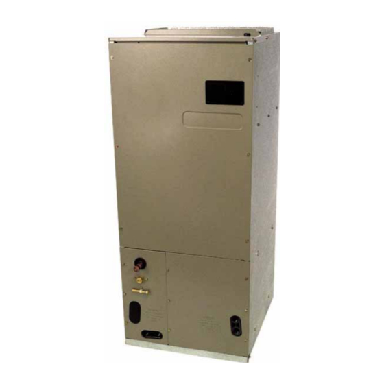
ATUF/ARUF/ARPF/ADPF/ASPF
AIR HANDLERS
I
& O
I
NSTALLATION
PERATING
NSTRUCTIONS
®
C
US
NOTE: ATUF models are suitable for Upflow and Horizontal Installations only.
Do not use for Downflow Installations
RECOGNIZE THIS SYMBOL AS A SAFETY PRECAUTION.
ATTENTION INSTALLING PERSONNEL
Prior to installation, thoroughly familiarize yourself with this Installation Manual. Observe all safety warnings.
During installation or repair, caution is to be observed.
It is your responsibility to install the product safely and to educate the customer on its safe use.
Goodman Manufacturing Company, L.P.
5151 San Felipe, Suite 500, Houston, TX 77056
IO-355E
www.goodmanmfg.com
08/10
© 2004-2010 Goodman Manufacturing Company, L.P.
Advertisement
Table of Contents

Related Manuals for Goodman ADPF


Summary of Contents for Goodman ADPF
- Page 1 ATUF/ARUF/ARPF/ADPF/ASPF AIR HANDLERS & O NSTALLATION PERATING NSTRUCTIONS ® NOTE: ATUF models are suitable for Upflow and Horizontal Installations only. Do not use for Downflow Installations RECOGNIZE THIS SYMBOL AS A SAFETY PRECAUTION. ATTENTION INSTALLING PERSONNEL Prior to installation, thoroughly familiarize yourself with this Installation Manual. Observe all safety warnings.
-
Page 2: Table Of Contents
Special Instructions ... 6 Downflow Conversion ... 7 Horizontal Conversion ... 8 Condensate Removal ... 8 ACHIEVING 2% LOW LEAKAGE RATE ... 9 ATUF/ARUF/ARPF/ADPF MOTOR ... 9 CFM Delivery ... 10 ASPF Motor ... 10 CFM Delivery ... 10 Thermostats ... 10 Start-Up Procedure ... -
Page 3: Important Note To Owner Regarding Product Warranty
To prevent the risk of property damage, personal injury, or death, do not store combustible materials or use gasoline or other flammable liquids or vapors in the vicinity of this unit. CARBON MONOXIDE POISONING HAZARD Special Warning for Installation of Furnace or Air Handling Units in Enclosed Areas such as Garages, Utility Rooms or Parking Areas Carbon monoxide producing devices (such as an automobile, space heater, gas water heater, etc.) should not be operated in enclosed areas... -
Page 4: Pre-Installation Instructions
“B” series, require external filtering. A washable filter is available as an accessory. To ensure opti- mum performance frequent filter cleaning is advised. Refer to Table 1 for the appropriate filter. ARUF ATUF ADPF ASPF ARPF 1729 1824 1824 1824... -
Page 5: Hkr Installation
HEAT KIT NOMINAL kW 1000 1200 1400 1600 1800 2000 Table 4 208/1/60 Supply Voltage - Temperature Rise Table °F NOTE: For installations not indicated above the following formula is to be used: TR = (kW x 3412) x (Voltage Correction) x 1.08 / CFM Where: TR = Temperature Rise = Heater Kit Actual kW... -
Page 6: Maximum Overcurrent Protection (Mop)
Maximum Overcurrent Protection (MOP) Every installation must include an NEC (USA) or CEC (Canada) approved overcurrent protection device. Also, check with local or state codes for any special regional re- quirements. Protection can be in the form of fusing or HACR style circuit breakers. -
Page 7: Downflow Conversion
2. After the gas has escaped, remove the nut and discard the black or brass cap. 3. Remove the check piston to verify it is correct and then replace the piston. See piston kit chart in instructions. 4. Use a tube cutter to remove the spin closure on the suction line. -
Page 8: Horizontal Conversion
Figure 4 To complete the conversion, slide the evaporator coil into the chassis and attach the three (3) access panels. (Figure Figure 5 NOTE: When converted to downflow position, the coil may protrude above the cabinet on some models. Horizontal Conversion Dedicated Downflow models are not suitable for horizontal application and must not be used for this type of installation. -
Page 9: Achieving 2% Low Leakage Rate
An additional drain hole cover is required. ATUF/ARUF/ARPF/ADPF MOTOR (Motor Speed Adjustment) The motors in all ATUF, ARUF, ARPF and ADPF motors are multi-speed PSC motors. The color of the wire coming from the motor to the “COM” terminal on the control board defines in which speed the motor will operate. -
Page 10: Cfm Delivery
CFM deliverd against External Static Pressure Model Speed 0.1" 0.2" High 1155 1090 ARUF172916 Med. High 1155 1090 ARUF182416 Med. High 1135 1085 ARUF193116 Med. High 1385 1315 ARUF303016 Med. 1340 1290 1075 1030 High 1310 1240 ARUF363616 Med. 1270 1210 1045 1005... -
Page 11: Start-Up Procedure
thermostat as shown in Figures 10 and 11. Goodman® part number CHT18-60 is a single-stage cool and single-stage heat thermostat. Goodman® part number HPT18-60 is a single-stage cool, two-stage heat pump thermostat. The first stage is heat pump heating and the second stage is optional electric heat. If additional features are desired, such as digital or program- mable capabilities, these thermostats are commercially avail- able. -
Page 12: Thermostat Wiring
HIGH VOLTAGE! WARNING MULTIPLE POWER SOURCES MAY BE PRESENT. FAILURE TO DO SO MAY CAUSE PROPERTY DAMAGE, PERSONAL INJURY OR DEATH. ROOM THERMOSTAT TO CONDENSING CONTACTOR UNIT 24V. CONNECTIONS COIL #18 GA. 2 WIRES Figure 8 - Low Voltage Wiring Diagram for Cooling Unit with optional heat kit 10kW and below #18 GA. - Page 13 HIGH VOLTAGE! WARNING MULTIPLE POWER SOURCES MAY BE PRESENT. FAILURE TO DO SO MAY CAUSE PROPERTY DAMAGE, PERSONAL INJURY OR DEATH. ATUF/ARUF/ARPF/ADPF 18-60 10 KW & BELOW HEAT PUMP O Y R #18 GA. 5 WIRE (OPTIONAL) OUTDOOR THERMOSTAT CLOSE ON TEMPERATURE FALL...
-
Page 14: Aspf Thermostat Connections
ASPF THERMOSTAT CONNECTIONS The following composite wiring diagrams detail various configurations in which the ASPF air handlers can be used. Ex- amples include single-stage cooling and heat pump with single or two-stage electric heating. All these configurations can be applied with convenient connections to outdoor thermostat applications. The following sections will be detailed: •... -
Page 15: Cooling Unit With Optional Heat Kits Of 15 Kw And Above And Room Thermostat With Two Stages Of Heat
HIGH VOLTAGE! WARNING MULTIPLE POWER SOURCES MAY BE PRESENT. FAILURE TO DO SO MAY CAUSE PROPERTY DAMAGE, PERSONAL INJURY OR DEATH. COOLING UNIT WITH OPTIONAL HEAT KITS OF 15 kW AND ABOVE AND ROOM THERMOSTAT WITH TWO STAGES OF HEAT HEAT PUMP UNIT WITH OPTIONAL HEAT KITS OF 10 kW AND BELOW NOTES: 1) OUTDOOR THERMOSTAT (OT-1) SHOULD BE THE... -
Page 16: Heat Pump Unit With Optional Heat Kits Of 15 Kw And Above
HIGH VOLTAGE! WARNING MULTIPLE POWER SOURCES MAY BE PRESENT. FAILURE TO DO SO MAY CAUSE PROPERTY DAMAGE, PERSONAL INJURY OR DEATH. HEAT PUMP UNIT WITH OPTIONAL HEAT KITS OF 15 kW AND ABOVE NOTES: 1) OUTDOOR THERMOSTAT (OT-1) SHOULD BE THE FIRST TO CLOSE AND THE LAST TO OPEN. -
Page 17: Electronic Blower Time Delay Relay
HIGH VOLTAGE! WARNING MULTIPLE POWER SOURCES MAY BE PRESENT. FAILURE TO DO SO MAY CAUSE PROPERTY DAMAGE, PERSONAL INJURY OR DEATH. NOTE: This is not applicable to ASPF models. ELECTRONIC BLOWER TIME DELAY RELAY TS T A T S Y S T E M X F M R- R T R AN S F O R M E R 2 4 V A C... - Page 18 THIS PAGE LEFT INTENTIONALLY BLANK...
- Page 19 THIS PAGE LEFT INTENTIONALLY BLANK...
- Page 20 Goodman Manufacturing Company, L.P. 5151 San Felipe, Suite 500, Houston, TX 77056 www.goodmanmfg.com © 2004-2010 Goodman Manufacturing Company, L.P.