Advertisement
TECHNICAL MANU
TECHNICAL MANU AL
TECHNICAL MANU
TECHNICAL MANU
TECHNICAL MANU
•
Refer to Service Manual RS6200006 for installation, operation & troubleshooting information.
•
All safety information must be followed as provided in the Service Manual.
•
Refer to the appropriate Parts Catalog for part number information.
•
Models listed on page 3.
This manual is to be used by qualified, professionally trained HVAC technicians only. Goodman
does not assume any responsibility for property damage or personal injury due to improper
service procedures or services performed by an unqualified person.
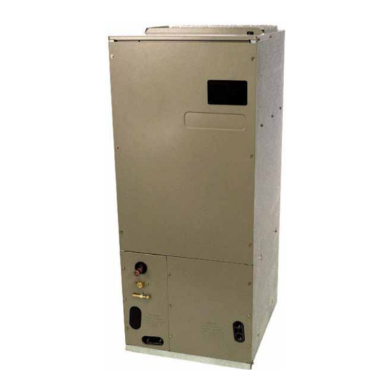
AVPTC Air Handlers
Copyright © 2010 - 2011
Goodman Manufacturing Company, L.P.
AL
AL
AL
AL
RT6121001r2
January 2011
Advertisement
Table of Contents

Summary of Contents for Goodman AVPTC AVPTC183014
- Page 1 TECHNICAL MANU AL TECHNICAL MANU TECHNICAL MANU TECHNICAL MANU TECHNICAL MANU AVPTC Air Handlers • Refer to Service Manual RS6200006 for installation, operation & troubleshooting information. • All safety information must be followed as provided in the Service Manual. • Refer to the appropriate Parts Catalog for part number information.
-
Page 2: Product Identification
PRODUCT IDENTIFICATION The model number is used for positive identification of component parts used in manufacturing. Please use this number when requesting service or parts information. PRODUCT TYPE: A: Air Handler CABINET FINISH: U: Unpainted P: Painted N: Uncased APPLICATION C: Ceiling Mount PSC Motor D: Downflow PSC Motor E: Multi-Position Varible Speed Motor... - Page 3 PRODUCT IDENTIFICATION The model number is used for positive identification of component parts used in manufacturing. Please use this number when requesting service or parts information. The United States Environmental Protection Agency (“EPA”) has issued various regulations re- WARNING WARNING garding the introduction and disposal of refrigerants introduced into this unit.
-
Page 4: Product Design
PRODUCT DESIGN WARNING When installing or servicing this equipment, safety clothing, including hand and eye protection, is strongly advised. If installing this equipment in an area that has special safety requirements (hard hats etc.), observe these requirements. To protect the unit when brazing close to the painted surfaces, the use of a quenching cloth is strongly advised to prevent scorching or marring of the equipment fin-... - Page 5 PRODUCT DESIGN When this product is installed in the downflow installation in an unconditioned space, remove the horizontal drain pan and install the following insulation kit AVPTC Model Insulation Kit 1830 DPI36-42/20 3137 DPI48-61/-20 4260 This kit is used to prevent sweating on the vertical drain pan. To prevent the horizontal drain pan from sweating in high humidity applications, it is recommended that a DPIH insulation accessory kit be used.
-
Page 6: Product Dimensions
PRODUCT DIMENSIONS INLET (FRONT VIEW) Model AVPTC183014 46 3/4" 22" 53 1/4" 24" AVPTC313714 AVPTC426014 53 1/4" 24" SUCTION LINE LIQUID LINE INLET TUBE 17 1/2" 19 1/2" 14 1/2" 20" 22" 12" 19 5/8" 20" 22" 12" 19 5/8" AVPTC INLET (RIGHT SIDE VIEW) -
Page 7: Product Specifications
PRODUCT SPECIFICATIONS Blower Wheel Diameter Width Lineset Connection Size Coil Drain Connection FPT Liquid Suction Electrical Data Voltage Min. Circuit Ampacity Max. Overcurrent Device (amps) Minimum VAC Maximum VAC Blower Motor Ship Weight (lbs) AVPTC183016* AVPTC313716* 9 1/2" 10 5/8" 8"... -
Page 8: Blower Performance Data
BLOWER PERFORMANCE DATA Speed Selection Dip Switches Cool Adjust Selection Selection Selection Switches Switches Switches OFF OFF OFF OFF OFF ON OFF Profiles Pre-Run Short-Run ------- -------- ------- ------- ------- ------- 30 sec/50% 30 sec/50% 30 sec/50% 30 sec/50% ------- ------- ------- -------... - Page 9 BLOWER PERFORMANCE DATA Indoor Control BIAS Dipswitches Switch 1 Switch 2 TERM1 / TERM2 = Termination dipswitches at outdoor unit. See installation instructions with CT Outdoor Control TERM TERM Dipswitch Dipswitches Switch 3 Switch 1 Switch 2 ON or ON or OFF compatiable outdoor unit.
-
Page 10: Wiring Diagrams
WIRING DIAGRAMS HTR1 ONE (1) ELEMENT ROWS NOTE: WHEN INSTALLING HEATER KIT, ENSURE SPEED TAP DOES NOT EXCEED MINIMUM BLOWER SPEED (MBS) SPEC IFIED FOR THE AIRHANDLER/HEAT ER KIT COMBINATION ON THIS UNIT'S S&R PLATE. AFTER INSTALLING OPTIONAL HEAT KIT, MARK AN "X" IN THE MARK ACCORDING TO NUMBER OF HEATER ELEMENT ROW S INSTALLED.


