Omron CJ Series Operation Manual
Sysmac temperature control units
Hide thumbs
Also See for CJ Series:
- Operation manual (304 pages) ,
- Connection manual (96 pages) ,
- Manual (38 pages)
Table of Contents
Advertisement
Quick Links
Download this manual
See also:
Operating Manual
Advertisement
Chapters
Table of Contents
Troubleshooting

Related Manuals for Omron CJ Series


Summary of Contents for Omron CJ Series
- Page 1 Cat. No. W396-E1-03 SYSMAC CJ Series CJ1W-TC@@@ Temperature Control Units OPERATION MANUAL...
- Page 2 CJ1W-TC@@@ Temperature Control Units Operation Manual Revised December 2005...
- Page 4 OMRON. No patent liability is assumed with respect to the use of the information contained herein. Moreover, because OMRON is con- stantly striving to improve its high-quality products, the information contained in this manual is subject to change without notice.
-
Page 6: Table Of Contents
TABLE OF CONTENTS PRECAUTIONS ........Intended Audience ............General Precautions . - Page 7 TABLE OF CONTENTS SECTION 4 Optional Settings........Shifting the Input Value (Input Compensation).
-
Page 8: About This Manual
Describes the use of Serial Communications CS1W-SCB21-V1/41-V1, CS1W-SCU21-V1, Unit and Boards to perform serial communica- CJ1W-SCU21/41 tions with external devices, including the usage Serial Communications Boards and Serial of standard system protocols for OMRON prod- Communications Units ucts. Operation Manual SYSMAC WS02-PSTC1-E W344... - Page 9 About this Manual, Continued Precautions provides general precautions for using the Temperature Control Unit, Programmable Controller, and related devices. Section 1 describes the features of the Temperature Control Unit and its basic system configuration. Section 2 describes the functions and specifications of the Temperature Control Unit, including techni- cal specifications, Unit parts, wiring, and data allocations.
- Page 10 WHETHER SUCH CLAIM IS BASED ON CONTRACT, WARRANTY, NEGLIGENCE, OR STRICT LIABILITY. In no event shall the responsibility of OMRON for any act exceed the individual price of the product on which liability is asserted. IN NO EVENT SHALL OMRON BE RESPONSIBLE FOR WARRANTY, REPAIR, OR OTHER CLAIMS...
- Page 11 Application Considerations SUITABILITY FOR USE OMRON shall not be responsible for conformity with any standards, codes, or regulations that apply to the combination of products in the customer's application or use of the products. At the customer's request, OMRON will provide applicable third party certification documents identifying ratings and limitations of use that apply to the products.
-
Page 12: Performance Data
Performance data given in this manual is provided as a guide for the user in determining suitability and does not constitute a warranty. It may represent the result of OMRON's test conditions, and the users must correlate it to actual application requirements. Actual performance is subject to the OMRON Warranty and Limitations of Liability. - Page 14 PRECAUTIONS This section provides general precautions for using the Temperature Control Unit, Programmable Controller, and related devices. The information contained in this section is important for the safe and reliable application of the Temperature Control Unit. You must read this section and understand the information contained before attempting to set up or operate a Temperature Control Unit and PC system.
-
Page 15: Intended Audience
It is extremely important that a PLC and all PLC Units be used for the speci- fied purpose and under the specified conditions, especially in applications that can directly or indirectly affect human life. You must consult with your OMRON representative before applying a PLC system to the above mentioned applica- tions. -
Page 16: Operating Environment Precautions
Operating Environment Precautions measure for such problems, external safety measures must be provided to ensure safety in the system. • When the 24-V DC output (service power supply to the PLC) is over- loaded or short-circuited, the voltage may drop and result in the outputs being turned OFF. -
Page 17: Application Precautions
Application Precautions • Locations subject to condensation as the result of severe changes in tem- perature. • Locations subject to corrosive or flammable gases. • Locations subject to dust (especially iron dust) or salts. • Locations subject to exposure to water, oil, or chemicals. •... - Page 18 Application Precautions • Fail-safe measures must be taken by the customer to ensure safety in the event that outputs from Output Units remain ON as a result of internal cir- cuit failures, which can occur in relays, transistors, and other elements. •...
- Page 19 Application Precautions • Mount Units only after checking terminal blocks and connectors com- pletely. • Be sure that the terminal blocks, Memory Units, expansion cables, and other items with locking devices are properly locked into place. Improper locking may result in malfunction. •...
-
Page 20: Conformance To Ec Directives
Concepts EMC Directives OMRON devices that comply with EC Directives also conform to the related EMC standards so that they can be more easily built into other devices or the overall machine. The actual products have been checked for conformity to EMC standards (see the following note). - Page 21 Conformance to EC Directives 2. You must use reinforced insulation or double insulation for the DC power supplies used for the communications power supply and I/O power sup- plies. 3. CS/CJ-series PLCs complying with EC Directives also conform to the Common Emission Standard (EN61000-6-4).
- Page 22 Conformance to EC Directives Countermeasure Examples When switching an inductive load, connect an surge protector, diodes, etc., in parallel with the load or contact as shown below. Circuit Current Characteristic Required element If the load is a relay or solenoid, there is The capacitance of the capacitor must CR method be 1 to 0.5 µF per contact current of...
-
Page 24: Features And System Configuration
SECTION 1 Features and System Configuration This section describes the features of the Temperature Control Unit and its basic system configuration. Introduction and Features ........1-1-1 Introduction. -
Page 25: Introduction And Features
Introduction and Features Section 1-1 Introduction and Features 1-1-1 Introduction The CJ1W-TC@@@ Temperature Control Units are Special I/O Units that receive inputs directly from thermocouple or platinum resistance thermome- ters, perform PID control with two degrees of freedom, and output results through open collector outputs. -
Page 26: Features
Section 1-1 Introduction and Features Word Allocation Data is exchanged between the CPU Unit and the Temperature Control Unit through the PLC’s memory areas. A part of the CIO Area (the Special I/O Unit Area) and part of the DM Area are reserved for the Special I/O Units. The Temperature Control Unit requires 20 words in the CIO Area and 100 words in the DM Area. - Page 27 Introduction and Features Section 1-1 ness in this design was that both responses could not be satisfied at the same time. 1. If the disturbance response were emphasized (i.e., P and I were re- duced and D was increased), the SV response would oscillate and overshoot.
- Page 28 Section 1-1 Introduction and Features Note The “limit-cycle method” uses ON/OFF operation to cause hunting around the SV, measures the amplitude and hunting period, and calculates the optimum PID constants. Control Operation The Temperature Control Unit’s control can be set to reverse operation or for- (Forward and Reverse) ward operation with pins 4 and 5 of the Unit’s DIP switch.
-
Page 29: System Configuration
E54-CT1 or E54-CT3 Note 1. An OMRON E54-CT1 or E54-CT3 Current Transformer must be used as the Current Transformer (CT). Do not use any other Current Transformer. 2. Turn ON the Stop Bit for the loop to stop temperature control. If PID control is being used and the heater is turned OFF using an operation switch input to the heater, PID control performance will be adversely affected. -
Page 30: Installation Procedure
System Configuration Section 1-2 The number of Units that can be mounted in a CPU Rack or Expansion Rack depends on the capacity of the Rack’s Power Supply Unit and the current con- sumption of the other Units in the Rack. The following table shows the maximum number of CJ1W-TC@@@ Tempera- ture Control Units that can be mounted in a Rack if the Temperature Control Units are the only Units being used in the Rack. - Page 31 Section 1-2 System Configuration An End Cover is provided with the CPU Unit. Always install this End Cover on the rightmost Unit in the PLC. The CJ-series PLC will not operate properly if the End Cover is not installed. Handling Precautions •...
- Page 32 Section 1-2 System Configuration !Caution A cold-junction compensator is attached to the terminal block for Temperature Control Units with thermocouples. The accuracy ratings are given for the Tem- perature Control Unit used in a set with the cold-junction compensator. Always use the Unit and terminal block in a set.
-
Page 33: Comparison To C200H Temperature Control Units
Section 1-3 Comparison to C200H Temperature Control Units Comparison to C200H Temperature Control Units Item CJ-series Temperature Control Units C200H Temperature Control Units Model number CJ1W-TC00@/10@ C200H-TC00@/10@ Unit type CJ-series Special I/O Unit C200H Special I/O Unit Compatible PLCs CJ-series PLCs CS-series, C200HX/HG/HE, C200HS, and C200H PLCs Number of control loops... -
Page 34: Specifications And Functions
SECTION 2 Specifications and Functions This section describes the functions and specifications of the Temperature Control Unit, including technical specifications, Unit parts, wiring, and data allocations. Specifications ..........2-1-1 Specifications . -
Page 35: Specifications
Specifications Section 2-1 Specifications 2-1-1 Specifications General Specifications Item Specification Unit classification CJ-series Special I/O Unit Compatible CJ-series CPU Rack or CJ-series Expansion Rack Racks Max. number of 10 Units/Rack max. (CPU Rack or Expansion Rack) Units CPU Unit data Special I/O Unit 20 words/Unit for CPU Unit to Tem-... - Page 36 Section 2-1 Specifications Item Specification 31 × 90 × 65 mm (W × H × D) Dimensions Weight 150 g max. Characteristics Item Specification Model number CJ1W-TC00@ CJ1W-TC10@ Temperature sensor Thermocouple: Types R, S, K, J, T, L, and B Platinum resistance thermometer: Types Pt100 and JPt100 Number of loops...
- Page 37 Specifications Section 2-1 Item Specification External terminal Removable terminal block with 18 points (M3 screws) connections Effect on the CPU 0.4 ms Unit’s cycle time Note 1. The last three digits of the model number indicate the Unit’s features: CJ1W-TC @ 0 @ 1: NPN outputs, four-loop control outputs Output type 2: PNP outputs, four-loop control outputs...
-
Page 38: Input Function Block Diagrams
Note 1. The maximum continuous heater current that can be detected at a CJ1W- TC@@@ Temperature Control Unit is 50 A. 2. Do not use any Current Transformer (CT) other than the OMRON E54-CT1 or E54-CT3 Current Transformer. 2-1-2 Input Function Block Diagrams... -
Page 39: Input Specifications
Section 2-1 Specifications 2-1-3 Input Specifications A switch on the front of the Unit (pin 3 of the DIP switch) selects whether the Temperature Control Unit’s data is stored and indicated as 4-digit BCD or binary (i.e., 4-digit hexadecimal). Pin 2 of the DIP switch selects whether the temperature is indicated in °... - Page 40 Specifications Section 2-1 2. The lower-limit indication for B-type thermocouples is 0 ° C or 0 ° F. 3. When the data format is BCD, the indicated temperature will remain fixed at the lower limit value or upper limit value when the temperature exceeds the allowed indication range but does not exceed the setting range.
-
Page 41: Application Procedure
Section 2-2 Application Procedure Application Procedure The procedure for installing and setting up the Temperature Control Unit is illustrated below. • Set the unit number on the front panel of the Tempera- Set unit number. ture Control Unit. • Set the Input Type Switch on the front panel of the Tem- Set the input type. -
Page 42: Example Operating Procedure
Section 2-2 Application Procedure 2-2-1 Example Operating Procedure The following settings are used in this example for a Four-loop Temperature Control Unit. Input type: Thermocouple K thermocouple (0.0 to 500.0 ° C) Input: Data format: The operating procedure through reading the process value for each loop is given in this section. - Page 43 5. Turn ON the power supply to the PLC. Creating I/O Tables There two different methods that can be used to create I/O tables with the CJ- series PLCs. Refer to the CJ Series Programmable Controllers Operation Manual (W393) for details. Automation Creation The PLC can be set to automatically create I/O tables at startup.
-
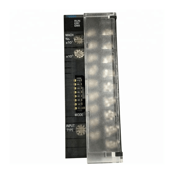
Page 44: Part Names And Functions
Part Names and Functions Section 2-3 CIO 201814 Sensor Error Flag for Loop 1 MOV(21) 2013 CIO 201914 D00100 Sensor Error Flag for Loop 2 MOV(21) 2014 CIO 202814 D00101 Sensor Error Flag for Loop 3 MOV(21) 2023 CIO 202914 D00102 Sensor Error Flag for Loop 4 MOV(21) -
Page 45: Unit Number Switches
Part Names and Functions Section 2-3 Indicator Name Color Status Meaning CPU Unit Error An error occurred in the CPU Unit. Not lit Normal operating status Output Indicators The Output Indicators light to indicate when the corresponding Temperature Control Unit output is ON. 2-3-3 Unit Number Switches The CPU Unit and the Temperature Control Unit exchange data through the... -
Page 46: Dip Switch Setting Functions
Section 2-3 Part Names and Functions 2-3-4 DIP Switch Setting Functions MODE ON is to the right. Function Factory setting Operation when CPU Unit is in Continue Stop PROGRAM mode °F °C Temperature units (°C/°F) Data format 16-bit binary 4-digit BCD Control operation (loops 1 and 3) Forward Reverse (cooling) -
Page 47: Setting The Input Type
Part Names and Functions Section 2-3 Control Operation for Pin 4 selects forward (cooling) operation (ON) or reverse (heating) operation Loops 1 and 3 (Pin 4) (OFF) for control loops 1 and 3. Control Operation for Pin 5 selects either forward (cooling) operation (ON) or reverse (heating) Loops 2 and 4 (Pin 5) operation (OFF) for control loops 2 and 4. -
Page 48: Wiring
Section 2-4 Wiring Wiring 2-4-1 Terminal Wiring Examples Thermocouple Temperature Control CJ1W-TC001 CJ1W-TC002 Units (4 loops, NPN outputs) (4 loops, PNP outputs) Input 2 − Input 2 − Input 1 − Input 1 − Input 2 + Input 2 + Input 1 + Input 1 + Cold-junction comp. -
Page 49: Output Circuits
Section 2-4 Wiring 2-4-2 Output Circuits The following diagrams show the internal output circuits. Output Circuits NPN Outputs (CJ1W-TC@01 and CJ1W-TC@03) 24 V Output Indicator NPN Outputs (CJ1W-TC@02 and CJ1W-TC@04) Output Indicator... -
Page 50: I/O Wiring Examples
Temperature Control Unit and Terminal Block with matching serial numbers. • Do not connect anything to the N.C. terminals. (The N.C. terminals cannot even be used as junction terminals.) • Do not connect any Current Transformer to the CT input terminals other than an OMRON E54-CT1 or E54-CT3. - Page 51 3. Do not connect any Current Transformer to the CT input terminals other than an OMRON E54-CT1 or E54-CT3. 4. Always attach crimp terminals to the wiring that connects to the terminal block and tighten the terminal screws securely. The terminal screws are M3 screws and need to be tightened to a torque of 0.5 N ⋅...
-
Page 52: Data Exchange With The Cpu Unit
Section 2-5 Data Exchange with the CPU Unit • Noise from the power supply line may be superimposed on I/O signals if equipment that generates high frequency noise is used nearby or the Temperature Control Unit’s power line is shared with electrical welding equipment or discharging equipment. -
Page 53: Data Exchange Settings
Section 2-5 Data Exchange with the CPU Unit 2-5-2 Data Exchange Settings Data Format The format used to store data during data exchange between the CPU Unit and Temperature Control Unit in the words allocated to the Temperature Con- trol Unit in the CIO and DM Areas must be set in advance. The data format is set using pin 3 on the DIP switch for function settings. -
Page 54: Memory In The Temperature Control Unit
Section 2-5 Data Exchange with the CPU Unit Special I/O Unit To restart the Unit after changing the contents of the DM Area or correcting an Restart Bits error, turn ON the power to the PLC again or turn the Special I/O Unit Restart Bit ON and then OFF again. -
Page 55: Operation Data
Section 2-5 Data Exchange with the CPU Unit Temperature Control Unit backup area Temperature Control Unit CPU Unit Operation I/O refresh Data Power ON Initialization or restart EPROM Data Save Bit I/O refresh turned ON Operating Parameters At power ON or restart if pin 8 of DIP switch is ON. - Page 56 Section 2-5 Data Exchange with the CPU Unit Operation Data The following tables show the specific applications of the bits and words in the Contents Operation Data. Four-loop Units Word Out- Loop 1 Set Point (SP) Loop 2 SP Loop 1 Loop 2 Loop 1 Loop 2...
- Page 57 Section 2-5 Data Exchange with the CPU Unit Two-loop Units Word Out- Loop 1 Set Point (SP) Loop 2 SP Loop 1 Loop 2 Loop 1 Loop 2 Loop 1 Loop 2 Loop 1 Loop 2 Save Save Change Change Stop Stop Stop AT...
- Page 58 Section 2-5 Data Exchange with the CPU Unit Operation Data Details on the Operation Data are provided in the following table. Refer to 2-6 Details Data Ranges for the ranges of data that can be used. Four-loop Units Address Loop Name Function Word...
-
Page 59: Loop
Section 2-5 Data Exchange with the CPU Unit Address Loop Name Function Word Bits Inputs 00 to 15 Loop 1 Process Value The current process value is stored in 4-digits BCD or 16-bits (Tempera- binary. 00 to 15 Loop 2 Process Value ture Con- For negative BCD values, the most significant digit will be F. - Page 60 Section 2-5 Data Exchange with the CPU Unit Address Loop Name Function Word Bits Inputs Loop 2 Save Com- The Save Completed Flag turns ON when writing data from (Tempera- pleted Flag RAM to EEPROM has been completed. The write is started by ture Con- turning ON bit 14 of CIO (n+2), the Save Bit.
-
Page 61: Loop
Section 2-5 Data Exchange with the CPU Unit Address Loop Name Function Word Bits Outputs n+10 00 to 15 Loop 3 Set Point Set the Set Point for the loop as 4-digit BCD or 16-bit binary. (CPU Unit n+11 00 to 15 Loop 4 Set Point For negative BCD values, set the most significant digit to F. -
Page 62: Loop
Section 2-5 Data Exchange with the CPU Unit Address Loop Name Function Word Bits Inputs n+13 00 to 15 Loop 3 Process Value The current process value is stored in 4-digits BCD or 16-bits (Tempera- binary. n+14 00 to 15 Loop 4 Process Value ture Con- For negative BCD values, the most significant digit will be F. -
Page 63: Input
Section 2-5 Data Exchange with the CPU Unit Address Loop Name Function Word Bits Inputs n+19 Loop 4 Save Com- The Save Completed Flag turns ON when writing data from (Tempera- pleted Flag RAM to EEPROM has been completed. The write is started by ture Con- turning ON bit 14 of CIO (n+12), the Save Bit. -
Page 64: Loop
Data Exchange with the CPU Unit Section 2-5 Two-loop Units Address Loop Name Function Word Bits Outputs 00 to 15 Loop 1 Set Point Set the Set Point for the loop as 4-digit BCD or 16-bit binary. (CPU Unit For negative BCD values, set the most significant digit to F. 00 to 15 Loop 2 Set Point to Tem- The values set here are transferred to RAM. -
Page 65: Loop
Data Exchange with the CPU Unit Section 2-5 Address Loop Name Function Word Bits Inputs 00 to 15 Loop 1 Process Value The current process value is stored in 4-digits BCD or 16-bits (Tempera- binary. 00 to 15 Loop 2 Process Value ture Con- For negative BCD values, the most significant digit will be F. - Page 66 Section 2-5 Data Exchange with the CPU Unit Address Loop Name Function Word Bits Inputs Loop 1 AL1 Flag The AL1/AL2 Flag is ON when the temperature is within the alarm (Tempera- range set for the input value. The flag is OFF when the tempera- AL2 Flag ture Con- ture is not within the alarm range set for the input value.
-
Page 67: Initialization Data
Data Exchange with the CPU Unit Section 2-5 Address Loop Name Function Word Bits Outputs n+10 00 to 15 Loop 1 Heater Burn- Set the heater burnout current in 4-digits BCD or 16-bits binary. (CPU Unit out Current If the value is set to 0.0, heater burnouts will not be detected. to Tem- n+11 00 to 15 Loop 2 Heater Burn-... - Page 68 Section 2-5 Data Exchange with the CPU Unit 3. If two or more Special I/O Units are assigned the same unit number, a “UNIT No. DPL ERR” error (in the Programming Console) will be generat- ed (A40113 will turn ON) and the PLC will not operate. Initialization Data The following table shows the specific applications of the bits and words in the Contents...
-
Page 69: Operating Parameters
Section 2-5 Data Exchange with the CPU Unit DM address Loop Setting Units Word Bits D (m+2) 00 to 15 Loop 1 Alarm 1 hysteresis Set each alarm’s hysteresis in 4-digit BCD or 16-bit binary, accord- ing to the Data Format set on the Temperature Control Unit’s DIP D (m+3) 00 to 15 Alarm 2 hysteresis... - Page 70 Data Exchange with the CPU Unit Section 2-5 Operating Parameters The following tables show the specific applications of the bits and words in the Contents Operating Parameters. DM word Loop Setting DM word Loop Setting Output D (m+10) Loop 1 Alarm 1 SV Output D (m+50) Loop 3...
- Page 71 Section 2-5 Data Exchange with the CPU Unit Operating Parameters The following table provides details of the Initialization Data settings. For more Details details, refer to 2-6 Data Ranges. DM word Loop Setting Description Output D (m+10) Loop 1 Alarm 1 SV Set in 4-digit BCD or 16-bit binary.
-
Page 72: Data Ranges
Section 2-6 Data Ranges Starting DM Area Word The starting DM Area word (m) for a Special I/O Unit is: m = 20000 + (100 × unit number) Data Ranges • Starting CIO word: n = 2000 + (10 × unit number) •... -
Page 73: Monitored Values
Section 2-6 Data Ranges Allocated word(s) Setting BCD range Binary range Units Default Memory protection value Loop 1: D (m+13) Control 0001 to 0099 0001 to 0063 Sec- The Temperature Con- Loop 2: D (m+23) Period onds trol Unit’s settings are Loop 3: D (m+53) written to RAM. -
Page 74: Settings Required For Temperature Control
SECTION 3 Settings Required for Temperature Control This section explains the various settings required for temperature control. Setting the Input Type ......... . . 3-1-1 Setting the Input Type Switch. -
Page 75: Setting The Input Type
Section 3-1 Setting the Input Type Setting the Input Type Set the input type of the temperature sensor being used. There are two types of Temperature Control Units available: One accepts thermocouple inputs and the other accepts platinum resistance thermometer inputs. Both types have an “INPUT TYPE”... -
Page 76: Selecting The Temperature Units
Section 3-2 Selecting the Temperature Units Selecting the Temperature Units The Temperature Control Unit can operate in ° C or ° F. Select the desired tem- perature units with pin 2 of the DIP switch on the front of the Unit. The temperature unit setting applies to all of the Unit’s control loops. -
Page 77: Selecting The Control Operation (Forward/Reverse)
Section 3-4 Selecting the Control Operation (Forward/Reverse) Selecting the Control Operation (Forward/Reverse) 3-4-1 Forward (Cooling)/Reverse (Heating) With forward operation (cooling), the manipulated variable is increased as the PV increases. With reverse operation (heating), the manipulated variable is increased as the PV decreases. Manipulated variable Manipulated variable 100%... -
Page 78: Selecting Pid Control Or On/Off Control
Section 3-5 Selecting PID Control or ON/OFF Control Selecting PID Control or ON/OFF Control A switch on the front of the Unit (pin 6 of the DIP switch) selects whether the Temperature Control Unit uses ON/OFF control or PID control with 2 degrees of freedom. -
Page 79: Setting The Set Point
Section 3-7 Setting the Set Point Starting DM Area Word The starting DM Area word (m) for a Special I/O Unit is: m = 20000 + (100 × unit number) Setting the Set Point 3-7-1 Setting the SP Set the set point (SP) in the corresponding word of the Operation Data in the CIO words allocated to the Unit. -
Page 80: Setting The Pid Constants
Section 3-9 Setting the PID Constants Control sensitivity (heating) Set point 3-8-2 Required Settings The control method, set point, and control sensitivity must be set to use ON/ OFF control. In this example, ON/OFF control is used for loop 1. The set point is 200 ° C and Example Settings the control sensitivity is 2 °... -
Page 81: Setting Pid Constants Manually
Section 3-9 Setting the PID Constants same time. Use this flag as an input condition in the CPU Unit’s ladder program and transfer the PID constants from the Operating Parameters’ input area to the word in the output area where the PID constants are stored. - Page 82 Section 3-9 Setting the PID Constants The PID Constants Calculated Flag will be turned OFF automatically when you turn ON the Change PID Constants Bit. Refer to Appendix B Sample Programs for an example ladder program that performs the steps outlined above. Timing Chart Start AT Bit AT in progress...
-
Page 83: Using The Alarm Output Function
Section 3-10 Using the Alarm Output Function • Changing D (The Derivative Time) Increasing D Overshooting, undershooting, and the set time are reduced, but hunting will occur from small changes in the system itself. Decreasing D Overshooting and undershoot- ing are increased. It takes time to return to the SP. -
Page 84: Setting The Alarm Hysteresis
Section 3-10 Using the Alarm Output Function Setting Alarm mode Alarm output function Alarm SV (X) is positive Alarm SV (X) is negative Lower-limit alarm with standby sequence Absolute-value upper-limit alarm Absolute-value lower-limit alarm 3-10-2 Setting the Alarm Hysteresis The hysteresis setting controls the ON/OFF switching of the alarm output, as shown in the following diagram. -
Page 85: Example Alarm Settings
Section 3-10 Using the Alarm Output Function ■ Restarting the Standby Sequence The standby sequence will be cleared once the PV leaves the alarm range, but the standby sequence will restart (reset) in the following situations: • At the start of operation (when power is turned ON or the Unit is restarted) •... -
Page 86: Using The Heater Burnout Alarm
Section 3-11 Using the Heater Burnout Alarm 3-10-5 Summary of Alarm Output Function Settings DM address Loop Setting Data format Units Initial value Word Bits Binary D (m+0) 12 to 15 Loop 1 Alarm 1 mode 0 to 9 0000 08 to 11 Alarm 2 mode 0 to 9... -
Page 87: Unit
HB output), either set the heater burnout current to 0.0, turn the power OFF and ON again, or restart the Temperature Control Unit. Note 1. Do not use any CT other than the OMRON E54-CT1 or E54-CT3 Current Transformer. 2. Set the desired heater burnout detection current in the Heater Burnout Current word. -
Page 88: Determining The Heater Burnout Current
Section 3-11 Using the Heater Burnout Alarm 3-11-3 Determining the Heater Burnout Current • Use the following equation to calculate the average of the normal current and the current with a heater burnout: Current in normal operation + current after heater burnout SV = •... -
Page 89: Starting And Stopping Temperature Control
Section 3-12 Starting and Stopping Temperature Control 3-12 Starting and Stopping Temperature Control 3-12-1 Run/Stop Control To start temperature control for a loop that has been stopped, turn OFF the corresponding Stop Bit in the output area of the CIO Area words allocated to the Temperature Control Unit. -
Page 90: Optional Settings
SECTION 4 Optional Settings This section explains how to use the input compensation value. Shifting the Input Value (Input Compensation) ..... . . Recovering from Sensor Not Connected Errors . -
Page 91: Shifting The Input Value (Input Compensation)
Section 4-1 Shifting the Input Value (Input Compensation) Shifting the Input Value (Input Compensation) • The input value is shifted by the “input compensation value” for all points in the sensor’s range. For example, if the input compensation value is set to 1.2 °... -
Page 92: Recovering From Sensor Not Connected Errors
Section 4-2 Recovering from Sensor Not Connected Errors Recovering from Sensor Not Connected Errors If a sensor is not connected for any loop, a sensor error will occur and the ERC indicator on the front panel of the Unit will light. When necessary, the control and alarm functions for any loop can be disabled. -
Page 94: Error And Alarm Processing
SECTION 5 Error and Alarm Processing This section provides information on troubleshooting and error processing. Error and Alarm Processing ........5-1-1 Identifying Errors with the LED Indicators . -
Page 95: Error And Alarm Processing
Error and Alarm Processing Section 5-1 Error and Alarm Processing 5-1-1 Identifying Errors with the LED Indicators The ERC Indicator or ERH Indicator will light if an alarm or error occurs in the Temperature Control Unit. (Front of Temperature Control Unit) Indicator Name Color... -
Page 96: Unit
Section 5-1 Error and Alarm Processing 5-1-3 Alarms Detected by the Temperature Control Unit The ERC Indicator will light when an alarm occurs that is detected by the Temperature Control Unit itself. The corresponding error flag will be turned ON in the Unit’s Special I/O Unit Area. A separate CIO word is allocated to each loop, as shown in the following table. - Page 97 Error and Alarm Processing Section 5-1 Starting CIO Area Word The starting CIO Area word (n) for a Special I/O Unit is: n = 2000 + (10 × unit number) ■ Setting Error Numbers Setting error Setting name Priority number No incorrect settings Alarm mode 1 Alarm mode 2...
-
Page 98: Unit
Section 5-1 Error and Alarm Processing 5-1-4 Errors Originating in the CPU Unit The ERH Indicator will light when the Temperature Control Unit cannot oper- ate normally because I/O refreshing is not being performed properly with Spe- cial I/O Units. An error in the CPU Unit or I/O bus can interfere with I/O refreshing. -
Page 99: Troubleshooting
Section 5-2 Troubleshooting Special I/O Unit Restart Bits Function Remarks A50200 Unit 0 Restart Bit The corresponding Special I/O Unit will restart when its Restart Bit is turned ON and A50201 Unit 1 Restart Bit OFF. A50215 Unit 15 Restart Bit A50300 Unit 16 Restart Bit A50714... -
Page 100: Troubleshooting From Symptoms: Measurement Errors
Troubleshooting Section 5-2 5-2-1 Troubleshooting from Symptoms: Measurement Errors Incorrect Measurement or No Measurement Step Possible Cause Remedy Connection The temperature sensor is connected to the wrong Wire temperature sensor correctly. terminals or polarity is reversed. The temperature sensor connected to the Temper- Replace the temperature sensor with one that is com- ature Control Unit is not compatible with the Unit. - Page 101 Section 5-2 Troubleshooting Step Possible Cause Remedy Usage There is a thermocouple input and the input termi- Connect a thermocouple. nals are shorted. The temperature sensor was replaced or switch Turn the power OFF and then ON again. settings were changed while the power was ON. Here is a simple method to check the temperature sensor inputs: Ω...
-
Page 102: Troubleshooting From Symptoms: Temperature Control Errors
Section 5-2 Troubleshooting 5-2-2 Troubleshooting from Symptoms: Temperature Control Errors Temperature Does Not Rise Step Possible Cause Remedy Connection The measured temperature is incorrect. Refer to 5-2-1 Troubleshooting from Symptoms: Mea- surement Errors for troubleshooting directions. There is no load connected to the control output Connect a load. - Page 103 Section 5-2 Troubleshooting Excessive Overshooting or Undershooting Step Possible Cause Remedy Connection The measured temperature is incorrect. Refer to 5-2-1 Troubleshooting from Symptoms: Mea- surement Errors for troubleshooting directions. A general-purpose temperature sensor is being Change to a sheathed sensor. used in a system with a very fast heating response.
-
Page 104: Troubleshooting From Symptoms: Output Errors
Change the wiring to control output that corresponds to i.e., one from an Output Unit. the CT input. The connected CT is not an OMRON E54-CT1 or CTs other than the OMRON E54-CT1 and E54-CT3 E54-CT3. cannot be used. Connect an E54-CT1 or E54-CT3. -
Page 106: Dimensions
Appendix A Dimensions All dimensions are in mm. CJ1W-TC@@@ Current Transformer (Sold Separately) E54-CT1 E54-CT3 2.36 dia. 12 dia. 5.8 dia. 10.5 Two M3 holes, Depth 4 Two 3.5 dia. holes... -
Page 108: Sample Programs
Appendix B Sample Programs Reading the Process Value Summary This program reads each loop’s process value (PV) data and stores the data in a DM Area word (D00100 to D00103 for loops 1 to 4). Each loop’s input value is read by the MOV Instruction when the loop’s Sensor Error Flag is OFF. - Page 109 Appendix B Sample Programs Writing the Set Point Summary This program writes the set point (SP) for loop 1. Example Unit Settings • Unit: CJ1W-TC001 Temperature Control Unit • Unit number: Note The unit number switches are on the front of the Unit. Refer to 2-3-3 Unit Number Switches for details. Example Program The Setting Error Flag for loop 1 is bit 09 of CIO (n+8).
-
Page 110: Unit
Appendix B Sample Programs Performing Autotuning and Refreshing the PID Constants Summary This program performs autotuning for loop 1 and refreshes the Temperature Control Unit’s PID constants with the calculated PID constants. Example Unit Settings • Unit: CJ1W-TC001 Temperature Control Unit •... -
Page 111: Unit
Appendix B Sample Programs Converting Data from Signed Binary to Signed BCD Summary This program converts binary setting/monitor values from signed binary (4 digits) to signed BCD (8 digits). • When the most significant bit (leftmost bit) in a word is 1, that word is treated as 2’s complement binary data. -
Page 112: Index
Index applications precautions xviii EC Directives errors UNIT No. DPL ERR Analog Output Unit operating environment precautions xvii precautions applications xviii operating environment xvii Programming Console errors Analog Output Unit Special I/O Unit Restart Bits Analog Output Unit UNIT No. DPL ERR Analog Output Unit... -
Page 114: Revision History
Revision History A manual revision code appears as a suffix to the catalog number on the front cover of the manual. Cat. No. W396-E1-03 Revision code The following table outlines the changes made to the manual during each revision. Page numbers refer to the previous version. - Page 116 The Netherlands Tel: (31)2356-81-300/Fax: (31)2356-81-388 OMRON ELECTRONICS LLC 1 East Commerce Drive, Schaumburg, IL 60173 U.S.A. Tel: (1)847-843-7900/Fax: (1)847-843-8568 OMRON ASIA PACIFIC PTE. LTD. 83 Clemenceau Avenue, #11-01, UE Square, Singapore 239920 Tel: (65)6835-3011/Fax: (65)6835-2711 OMRON (CHINA) CO., LTD. Room 2211, Bank of China Tower,...
- Page 117 Authorized Distributor: Cat. No. W396-E1-03 Note: Specifications subject to change without notice Printed in Japan This manual is printed on 100% recycled paper.