
Related Manuals for Clarke Woodworker CS6-9C


Summary of Contents for Clarke Woodworker CS6-9C
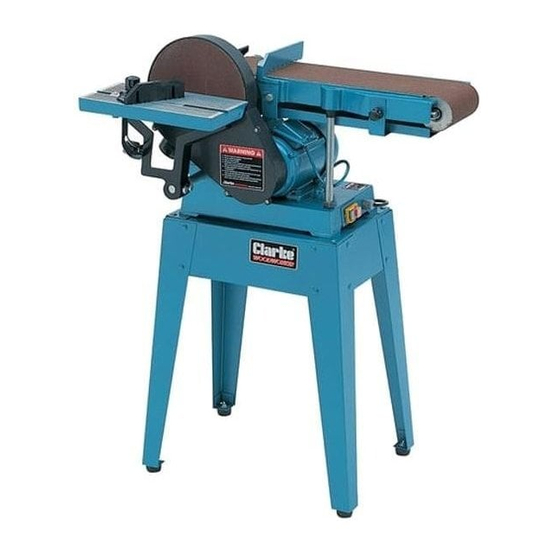
- Page 1 BELT & DISC SANDER BELT & DISC SANDER MODEL No. CS6-9C Part No. 6500420 OPERATING & MAINTENANCE INSTRUCTIONS 0206...
- Page 2 - 2 -...
-
Page 3: Table Of Contents
Thank you for purchasing this CLARKE Belt and Disc Sander, which is designed for workshop use and comprises a 9” dia. sanding disc and a 6” wide sanding belt. This machine is designed for sanding WOOD ONLY. DO NOT USE for sanding asbestos, or materials containing asbestos, painted surfaces, or materials which produce toxic dust. -
Page 4: General Safety Rules
GENERAL SAFETY RULES 1. ALWAYS KEEP GUARDS IN PLACE and 9. ALWAYS DISCONNECT FROM THE MAINS before attempting any kind of service check they are not damaged. work or adjustment or when changing 2. ALWAYS REMOVE ADJUSTING KEYS AND accessories such as grinding wheels. WRENCHES. -
Page 5: Electrical Connections, Fuse Rating
ELECTRICAL CONNECTIONS Connect the mains lead to a standard, 230 volt (50Hz) electrical supply through a fused good quality 13 amp BS 1363 plug, or a suitable fused isolator switch. WARNING: THIS APPLIANCE MUST BE EARTHED IMPORTANT: The wires in the mains lead are coloured in accordance with the following code: Green &... -
Page 6: Pre-Assembly Check
Unpack the carton and lay out the components and loose items. Check against the list below to ensure that all parts are present. If any damage has occurred during transit, please contact your Clarke dealer immediately. Fig.1 Main Body complete... -
Page 7: Assembly
ASSEMBLY Assemble the stand in the manner shown in Fig.2. The four top panels are secured with a single bolt, with flat washer, in each corner, and the legs are then bolted on, followed by the leg braces. Do not tighten the nuts until all bolts are in place and the stand is rocked vigorously to ensure it is stable. -
Page 8: Fitting The Table
With the belt raised, ensure that nothing can interfere Fig. 4 with the disc or belt, and that the Belt Tensioning Lever (1, Fig.4), is pushed fully to the rear - in the direction of the arrow. Plug in to the mains supply and press the GREEN ON button, marked ‘I’... -
Page 9: Methods Of Use
B...to the Belt Fig. 6 Before attempting to attach the table to the belt mounting, raise the belt arm and secure with the two securing screws, as explained under ‘Checks Before Use’, p7. Slide the Table Support bar into the mounting as shown in fig. - Page 10 Fig. 8A shows the table being used in Fig. 8A conjunction with the Mitre Gauge. Set the gauge to the angle you require and hold the workpiece firmly against the gauge, feeding it gently into the disc. Keep the workpiece in contact with the left side of the disc as far as possible.
-
Page 11: Dust Extraction
AND belt. The dust extraction outlets are shown in Fig.10 and have an outside diameter of 56mm (2 ”). Connect a suitable hose to a vacuum cleaner via a reducer, or Dust Extraction device (see your Clarke dealer). - 11 -... -
Page 12: Maintenance
MAINTENANCE CAUTION: Before carrying out any maintenance or servicing, ALWAYS ensure the plug is disconnected from the mains supply. A. Changing the Belt 1. Raise the table and secure in the vertical position. Fig. 11 2. Remove the lower Belt Cover, by slackening the four securing screws sufficiently for the cover to be slipped off. -
Page 13: Accessories
Fuse Rating ............13Amps Belt Speed ............5.6 M/s Belt Size ............150 x 1219mm (6x48in) Disc Speed ............1400RPM Disc Size ............230mm (9in) Gross Weight ............ 51.5kg Model No............CS6-9C Part No............. 6500420 - 13 -... -
Page 14: Parts List And Diagram
PARTS LIST Description Part No. No.. Description Part No. Rubber pad HTCS6901 Screw M4x12 HTCS6943 Side plate HTCS6902 Washer HTCS6944 Bolt M8x12 HTCS6903 Drive roller shaft HTCS6945 Nut M6 HTCS6904 Key B5x28 HTCS6946 Washer HTCS6905 Dust extraction outlet cover HTCS6948 Long plate HTCS6906 Screw M8x12... - Page 15 PARTS DIAGRAM - 15 -...