Table of Contents
Advertisement
Quick Links
Download this manual
See also:
Owner's Manual
REV.2007.07.03
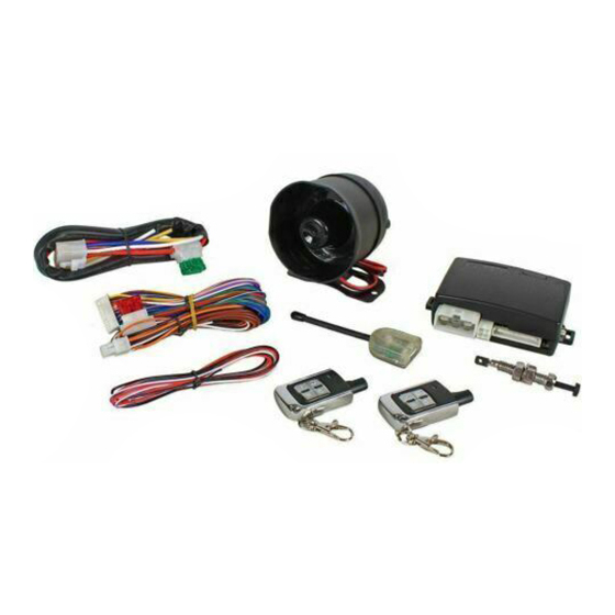
450 SERIES
A
V
S
S
DVANCED
EHICLE
ECURITY
YSTEM
TM
INSTALL GUIDE
www.ultrastarters.com
FCC ID NOTICE
This device complies with Part 15 of the FCC rules. Operation is subject to the following conditions:
1. This device may not cause harmful interference, and
2.This device must accept any interference received, including interference that may cause undesired operation.
CAUTION: Changes or modifications not expressly approved by the part responsible for compliance void the user's authority to operate
this devise.
Advertisement
Table of Contents

Related Manuals for Ultra Start 450 SERIES


Summary of Contents for Ultra Start 450 SERIES
-
Page 1: Program Menu
REV.2007.07.03 450 SERIES DVANCED EHICLE ECURITY YSTEM INSTALL GUIDE www.ultrastarters.com FCC ID NOTICE This device complies with Part 15 of the FCC rules. Operation is subject to the following conditions: 1. This device may not cause harmful interference, and 2.This device must accept any interference received, including interference that may cause undesired operation. -
Page 2: Table Of Contents
450 SERIES PAGE 2 INSTALL MANUAL SYSTEM PROGRAMMING - Menu 1 TABLE OF CONTENTS Wire Diagram..............Page 3 Quick View Programing Chart........Page 4 Program Menu 1 Page 4 Program Menu 2 Page 4 Transmitter Programming..........Page 5 System Wiring..............Page 6-9 10 Pin Connector... -
Page 3: Install Manual
450 SERIES PAGE 3 WIRE DIAGRAM INSTALL MANUAL SYSTEM PROGRAMMING - Menu 1 POSITIVE PARK LIGHT OUTPUT (+15amp) WHITE SYSTEM CHASSIS GROUND INPUT BLACK CONSTANT 12 VOLT INPUT (20AMP) OUTPUT TO ACTIVATE SIREN (+2amp) BROWN OUTPUT FOR TRUNK RELEASE (-) -
Page 4: Quick View Programing Chart
450 SERIES PAGE 4 INSTALL MANUAL SYSTEM PROGRAMMING - Menu 1 QUICK VIEW PROGRAM CHART ENTERING PROGRAM MODE To Enter Program Mode 1 - Cycle the Ignition Key On/Off On/Off On (Leaving the key ON) 2 - Press and release the Program Switch 1 time. -
Page 5: Transmitter Programming
450 SERIES PAGE 5 TRANSMITTER PROGRAMMING INSTALL MANUAL SYSTEM PROGRAMMING - Menu 1 TRANSMITTER PROGRAMMING The system can lean up to 4 different remote’s. Each remote to be used MUST be programmed together during the same sequence. For security, when a new remote is programmed all previous remote’s are deleted. -
Page 6: System Wiring
450 SERIES PAGE 6 INSTALL MANUAL SYSTEM PROGRAMMING - Menu 1 SYSTEM WIRING 10 PIN CONNECTOR OUTPUT TO ACTIVATE SIREN (+2amp) BROWN OUTPUT FOR TRUNK RELEASE (-) GRAY AUXILIARY CHANNEL 5 OUTPUT (-) WHT/BLUE STARTER DISABLE (-) WHEN ARMED ORANGE... - Page 7 450 SERIES PAGE 7 SYSTEM WIRING INSTALL MANUAL SYSTEM PROGRAMMING - Menu 1 Pin 1- Brown Wire- Siren Output (3amp Maximum) Connect this wire to the brown or red wire from the alarm siren. Pin 2- Grey Wire- Trunk Release/Auxiliary Channel 2 (-250ma Output) This output activates for 0.75 sec when the unlock button is held for 5 seconds.
-
Page 8: Door Lock Connector
450 SERIES PAGE 8 INSTALL MANUAL SYSTEM PROGRAMMING - Menu 1 SYSTEM WIRING 3 PIN KEYLESS CONNECTOR GREEN NEGATIVE OUTPUT FOR LOCK 12+ OUTPUT FOR DOOR LOCK MODULE NEGATIVE OUTPUT FOR UNLOCK BLUE FOR MORE DETAILED INFORMATION ON PROGRAMMING, WIRING DIAGRAMS, DOOR LOCK CONFIGURATION AND OTHER INFORMATION, PLEASE VISIT WWW.ULTRASTARTERS.COM/DIAGRAMS... -
Page 9: System Reset
450 SERIES PAGE 9 SYSTEM RESET INSTALL MANUAL SYSTEM PROGRAMMING - Menu 1 3 PIN KEYLESS CONNECTOR This connector is used when installing the optional keyless entry feature. If the door lock type of the vehicle is not negative see the following pages for the appropriate door lock diagram. -
Page 10: System Programming
450 SERIES PAGE 10 INSTALL MANUAL SYSTEM PROGRAMMING - Menu 1 PROGRAMMING STEP 1 - ENTER PROGRAM MODE MENU 1 1 CHIRP Cycle the Ignition Key Siren will chip to confirm Press Lock Button on Press and release the ON/OFF ON/OFF ON... - Page 11 450 SERIES PAGE 11 PROGRAMMING INSTALL MANUAL SYSTEM PROGRAMMING - Menu 1 SETTING 4- LOCKS TIMING PRESS 4 CHIRPS THE SIREN WILL CHIRP 4 TIMES WHEN SETTING 4 IS SELECTED 4 TIMES CHANGE SETTING 4 - PRESS & HOLD THE VALET SWITCH UNTIL THE SIREN CHIRP(S) GOTO SETTING 5 - PRESS &...
- Page 12 450 SERIES PAGE 12 INSTALL MANUAL SYSTEM PROGRAMMING - Menu 1 PROGRAMMING STEP 1 - ENTER PROGRAM MODE - MENU 2 1 CHIRP Cycle the Ignition Key Siren will chip to confirm Press Unlock Button on Press and release the...
-
Page 13: Shock Sensor Programing
450 SERIES PAGE 13 SHOCK SENSOR ADJUSTMENT INSTALL MANUAL SYSTEM PROGRAMMING - Menu 1 SHOCK SENSOR ADJUSTMENTS 1 - ENTER SHOCK SENSOR ADJUSTMENT MODE Press & HOLD Lock + Unlock buttons at the same time Continue to hold for 3-5 seconds Until Siren Chirps 3 times... -
Page 14: Valet / Service Mode
450 SERIES PAGE 14 INSTALL MANUAL SYSTEM PROGRAMMING - Menu 1 VALET MODE VALET MODE / EMERGENCY OVERRIDE This feature will disable or re-enable the alarm without the use of the remote transmitter. This feature will work when alarm in either an armed, disarmed or triggered state. When the system's override had been activated, door lock and trunk features will still be operational however the alarm will be active. -
Page 15: Diagnostics
450 SERIES PAGE 15 DIAGNOSTICS INSTALL MANUAL SYSTEM PROGRAMMING - Menu 1 ALARM STATUS / DIAGNOSTICS If the alarm system is triggered, the system will retain in memory the cause of the trigger. When disarming the alarm, the siren/horn will chirp 3 times to indicate the alarm had been triggered. -
Page 16: Quick View Operation Chart
450 SERIES PAGE 16 INSTALL MANUAL SYSTEM PROGRAMMING - Menu 1 QUICK VIEW OPERATION CHART CHIRP / BUTTON BUTTON PRESS SYSTEM FUNCTION FLASH 1 SEC LOCK / ARM ALARM 3 SEC ACTIVATE PANIC PRESS THEN ACTIVATE CONSTANT LOCK RELEASE THEN... - Page 17 450 SERIES PAGE 17 QUICK VIEW OPERATION CHART INSTALL MANUAL SYSTEM PROGRAMMING - Menu 1 SECOND CAR OPERATION/ PADLOC. SEE TRANSMITTER PROGRAMMING FOR INFORMATION ON PROGRAMMING THIS FEATURE. CHIRP / BUTTON BUTTON PRESS SYSTEM FUNCTION FLASH 1 SEC LOCK / ARM ALARM...
-
Page 18: Installer Check Sheet & Notes
450 SERIES PAGE 18 INSTALL MANUAL SYSTEM PROGRAMMING - Menu 1 INSTALLER NOTES INSTALLER PROGRAM OPTION CHART - PLACE A CHECK MARK BY THE OPTION PROGRAMMED PROGRAM MODE 1 SETTING # SETTING OPTION 1 OPTION 2 OPTION 3 LED FLASHES... -
Page 19: Product Warranty
450 SERIES PAGE 19 WARRANTY INSTALL MANUAL SYSTEM PROGRAMMING - Menu 1 SYSTEM PROGRAMMING - Menu 1 Applicated Security Technologies, Inc. ("AST") promises to the original purchaser to repair or replace with a comparable reconditioned model any AST control module ("module") excluding without limitation the any... -
Page 20: Contact Information
technical support: support@ultrastarters.com additional product information: www.ultrastarters.com...