NordicTrack Gx 3.4 Bike User Manual
English manual
Hide thumbs
Also See for Gx 3.4 Bike:
- (32 pages) ,
- Uživatelská příručka (32 pages) ,
- Gebruikershandleiding (32 pages)
Table of Contents
Advertisement
USER'S MANUAL
Model No. NTEVEX78612.0
Serial No.
Write the serial number in the space
above for reference.
Serial Number Decal
(under frame)
CUSTOMER SERVICE
UNITED KINGDOM
Call: 08457 089 009
From Ireland: 053 92 36102
Website: www.iconsupport.eu
E-mail: csuk@iconeurope.com
Write:
ICON Health & Fitness, Ltd.
c/o HI Group PLC
Express Way
CASTLEFORD
WF10 5QJ
UNITED KINGDOM
AUSTRALIA
Call: 1800 993 770
E-mail: australiacc@iconfitness.com
Write:
ICON Health & Fitness
PO Box 635
WINSTON HILLS NSW 2153
AUSTRALIA
CAUTION
Read all precautions and instruc-
tions in this manual before using
this equipment. Keep this manual
for future reference.
www.iconeurope.com
Advertisement
Table of Contents

Related Manuals for NordicTrack Gx 3.4 Bike


Summary of Contents for NordicTrack Gx 3.4 Bike
- Page 1 USER’S MANUAL Model No. NTEVEX78612.0 Serial No. Write the serial number in the space above for reference. Serial Number Decal (under frame) CUSTOMER SERVICE UNITED KINGDOM Call: 08457 089 009 From Ireland: 053 92 36102 Website: www.iconsupport.eu E-mail: csuk@iconeurope.com Write: ICON Health &...
-
Page 2: Table Of Contents
If a decal is missing or illegible, see the front cover of this manual and request a free replacement decal. Apply the decal in the location shown. Note: The decal(s) may not be shown at actual size. NORDICTRACK is a registered trademark of ICON IP, Inc. -
Page 3: Important Precautions
IMPORTANT PRECAUTIONS WARNING: To reduce the risk of serious injury, read all important precautions and instructions in this manual and all warnings on your exercise bike before using your exercise bike. ICON assumes no responsibility for personal injury or property damage sustained by or through the use of this product. -
Page 4: Before You Begin
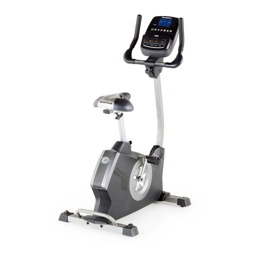
BEFORE YOU BEGIN Thank you for selecting the revolutionary reading this manual, please see the front cover of this NORDICTRACK GX 3.4 exercise bike. Cycling is an manual. To help us assist you, note the product model ® effective exercise for increasing cardiovascular fitness, number and serial number before contacting us. -
Page 5: Part Identification Chart
PART IDENTIFICATION CHART Use the drawings below to identify small parts used in assembly. The number in parentheses by each drawing is the key number of the part, from the PART LIST near the end of this manual. The number following the key num- ber is the quantity needed for assembly. -
Page 6: Assembly
ASSEMBLY • Assembly requires two persons. • In addition to the included tool(s), assembly requires the following tools: • Place all parts in a cleared area and remove the one Phillips screwdriver packing materials. Do not dispose of the packing materials until you complete all assembly steps. - Page 7 3. Attach the Front Stabilizer (2) to the Frame (1) with two M10 x 95mm Screws (76). 4. Loosen the Adjustment Knob (27) in the Frame (1) a few turns. Orient the Seat Post (6) as shown. Then, pull the Adjustment Knob (27) outward and insert the Adjustment Seat Post into the Frame (1).
- Page 8 5. Orient the Seat (23) and the Seat Carriage (24) as shown. Attach the Seat (23) to the Seat Carriage (24) with four M8 Locknuts (72) and four M8 Split Washers (75). Slide the Seat Carriage (24) onto the Seat Post (6).
- Page 9 7. While another person holds the Console (13) near the Handlebar (5), connect the wires on the Console to the Upper Wire (59), the Pulse Wire (61), and the Receiver Wire (16). Avoid pinching Insert the excess wire into the Handlebar (5). the wires Tip: Avoid pinching the wires.
- Page 10 9. Slide the Front Shield Cover (7) upward onto the Upright (4). While another person holds the Upright (4) near the Frame (1), connect the Upper Wire (59) to the Lower Wire (58). Insert the Upright (4) into the Frame (1). Tip: Avoid pinching the wires.
- Page 11 11. Plug the Power Adapter (67) into the receptacle on the frame of the exercise bike. If necessary, plug the Power Adapter (67) into the Plug Adapter (B). Note: To plug the Power Adapter (67) into an outlet, see HOW TO PLUG IN THE POWER ADAPTER on page 13.
-
Page 12: The Chest Heart Rate Monitor
THE CHEST HEART RATE MONITOR HOW TO PUT ON THE HEART RATE MONITOR • Do not expose the heart rate monitor to direct sun- light for extended periods of time; do not expose it to The heart rate temperatures above 122° F (50° C) or below 14° F monitor consists of (-10°... -
Page 13: How To Use The Exercise Bike
HOW TO USE THE EXERCISE BIKE HOW TO PLUG IN THE POWER ADAPTER HOW TO ADJUST THE HEIGHT OF THE SEAT IMPORTANT: If the exercise bike has been exposed For effective exercise, the seat should be at the proper to cold temperatures, allow it to warm to room height. - Page 14 HOW TO ADJUST THE ANGLE OF THE HOW TO ADJUST THE PEDAL STRAPS HANDLEBAR To adjust the To adjust the angle of the handlebar, first loosen the pedal straps, first adjustment knob a few turns. Next, pull the knob out- pull the ends of ward, pivot the handlebar to the desired angle, and the straps off the...
- Page 15 CONSOLE DIAGRAM MAKE YOUR FITNESS GOALS A REALITY WITH IFIT.COM With your new iFit-compatible fitness equipment, you can use an array of features on iFit.com to make your fitness goals a reality: Exercise anywhere in the world with customizable Google Maps. Download training workouts designed to help you reach your personal goals.
- Page 16 FEATURES OF THE CONSOLE The console also features an iFit mode that enables the console to communicate with your wireless network The advanced console offers an array of features through an optional iFit module. With the iFit mode, designed to make your workouts more effective and you can download personalized workouts, create your enjoyable.
- Page 17 HOW TO USE THE MANUAL MODE Calories per Hour (Cals./Hr)—This display mode will show the approximate number of calories you 1. Begin pedaling or press any button on the are burning per hour. console to turn on the console. Distance (Dist.)—This display mode will show When you turn on the console, the display will turn the distance that you have pedaled in miles or on.
- Page 18 If there are As you exercise, the workout intensity level bar will indicate the approximate intensity level of your sheets of plas- exercise. tic on the metal contacts on the handgrip heart rate monitor, remove the plas- tic. To measure Contacts your heart rate, hold the handgrip...
- Page 19 HOW TO USE AN ONBOARD WORKOUT resistance level and/or target speed is programmed for the next segment, the resistance level and/or 1. Begin pedaling or press any button on the target speed will appear in the display for a few console to turn on the console.
- Page 20 HOW TO USE A SET-A-GOAL WORKOUT Make sure to pedal at a speed that is comfort- able for you. 1. Begin pedaling or press any button on the console to turn on the console. Note: The calorie goal is an estimate of the number of calories that you will burn during When you turn on the console, the display will turn the workout.
- Page 21 HOW TO USE A WATTS WORKOUT Watts workout 2 or 3 is divided into one-minute segments. One resistance level and one watts 1. Begin pedaling or press any button on the goal are programmed for each segment. Note: The console to turn on the console. same resistance level and/or watts goal may be programmed for consecutive segments.
- Page 22 HOW TO USE AN IFIT WORKOUT 4. Select an iFit workout. You must have an iFit module to use an iFit workout. To download an iFit workout in your schedule, press the Map, Train, or Lose Wt. button to down- To purchase an iFit module at any time, go to load the next workout of that type in your schedule.
- Page 23 5. Start the workout. HOW TO USE THE SOUND SYSTEM See step 3 on page 19. To play music or audio books through the console sound system while you exercise, plug your audio During some workouts, the voice of a personal cable into the jack on the console and into a jack on trainer will guide you through your workout.
- Page 24 HOW TO CHANGE CONSOLE SETTINGS If no module is connected, the display will show the words NO IFIT MODULE. If no module is con- The console features a user mode that allows you to nected, go to step 10. view usage information, select a unit of measurement, 6.
-
Page 25: Maintenance And Troubleshooting
MAINTENANCE AND TROUBLESHOOTING Inspect and tighten all parts of the exercise bike regu- Next, rotate the larly. Replace any worn parts immediately. Left Crank Arm (20) to a vertical To clean the exercise bike, use a damp cloth and a position with the small amount of mild soap. - Page 26 HOW TO ADJUST THE DRIVE BELT Next, rotate the Right Crank Arm (19) to a vertical position with the end of the Right Crank Arm pointing If you can feel the pedals slip while you are pedaling, upward. even when the resistance is adjusted to the highest level, the drive belt may need to be adjusted.
-
Page 27: Exercise Guidelines
EXERCISE GUIDELINES Burning Fat—To burn fat effectively, you must exer- WARNING: cise at a low intensity level for a sustained period of Before beginning this time. During the first few minutes of exercise, your or any exercise program, consult your physi- body uses carbohydrate calories for energy. - Page 28 SUGGESTED STRETCHES The correct form for several basic stretches is shown at the right. Move slowly as you stretch; never bounce. 1. Toe Touch Stretch Stand with your knees bent slightly and slowly bend forward from your hips. Allow your back and shoulders to relax as you reach down toward your toes as far as possible.
-
Page 29: Part List
PART LIST Model No. NTEVEX78612.0 R0113A Key No. Qty. Description Key No. Qty. Description Frame Idler Front Stabilizer Motor Bracket Rear Stabilizer Resistance Motor Upright Resistance Disc Handlebar Resistance Arm Seat Post M6 x 70mm Bolt Set Front Shield Cover M6 x 60mm Bolt Set Top Shield Cover Resistance Bracket... - Page 30 Key No. Qty. Description Key No. Qty. Description M4 x 19mm Screw Snap Ring M4 x 16mm Screw Power Receptacle/Wire M4 x 5mm Bright Screw – Assembly Tool Handlebar Pivot Bushing – User’s Manual M4 x 19mm Flat Head Screw Note: Specifications are subject to change without notice.
-
Page 31: Exploded Drawing
EXPLODED DRAWING Model No. NTEVEX78612.0 R0113A... -
Page 32: Ordering Replacement Parts
ORDERING REPLACEMENT PARTS To order replacement parts, please see the front cover of this manual. To help us assist you, be prepared to provide the following information when contacting us: • the model number and serial number of the product (see the front cover of this manual) • the name of the product (see the front cover of this manual) • t he key number and description of the replacement part(s) (see the PART LIST and the EXPLODED DRAWING near the end of this manual) RECYCLING INFORMATION This electronic product must not be disposed of in municipal waste.