Table of Contents
Advertisement
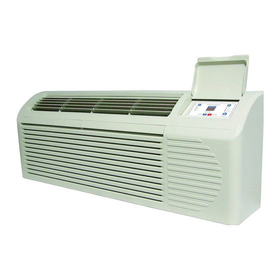
SERVICE MANUAL
Air Conditioners & Heat Pumps
Heat Controller, Inc. • 1900 Wellworth Ave. • Jackson, MI 49203 • (517)787-2100 • www.heatcontroller.com
Packaged Terminal
7,000-15,000 BTUH
Cooling with Electric Heat
EKTC07-1G
EKTC09-1G
EKTC12-1G
EKTC15-1G
Heat Pump with Electric Heat
EKTH07-1G
EKTH09-1G
EKTH12-1G
EKTH15-1G
EKTC07-2G
EKTC09-2G
EKTC12-2G
EKTC15-2G
EKTH07-2G
EKTH09-2G
EKTH12-2G
EKTH15-2G
Advertisement
Table of Contents

Related Manuals for Heat Controller EKTC07-1G


Summary of Contents for Heat Controller EKTC07-1G
- Page 1 Cooling with Electric Heat EKTC07-2G EKTC07-1G EKTC09-1G EKTC09-2G EKTC12-2G EKTC12-1G EKTC15-2G EKTC15-1G Heat Pump with Electric Heat EKTH07-2G EKTH07-1G EKTH09-1G EKTH09-2G EKTH12-2G EKTH12-1G EKTH15-1G EKTH15-2G Heat Controller, Inc. • 1900 Wellworth Ave. • Jackson, MI 49203 • (517)787-2100 • www.heatcontroller.com...
-
Page 2: Unit Nomenclature
PACKAGED TERMINAL A/C SERVICE MANUAL Heat Controller, Inc. UNIT NOMENCLATURE E K T C 0 7 - 1 G MODEL REVISION EKTC—Cooling only with Electric Heat G=Green R-410A Refrigerant Gas EKTH—Heat Pump with Electric Heat BTU/H VOLTAGE CODE 1=208/230V-60Hz 2=265V-60Hz (consult factory) DIMENSIONAL DATA 42”... -
Page 3: Unit Components
Heat Controller, Inc. SERVICE MANUAL Packaged Terminal A/C UNIT COMPONENTS... - Page 4 PACKAGED TERMINAL A/C SERVICE MANUAL Heat Controller, Inc. Specification and Technical Parameters Model EKTC07-1G EKTH07-1G Function Cooling Heating Cooling Heating Rated Voltage 230/208V 230/208V Rated Frequency 60Hz 60Hz Cross Flow Fan - 1 Cross Flow Fan - 1 Fan Type-Piece Diameter-Length in.
- Page 5 Heat Controller, Inc. SERVICE MANUAL Packaged Terminal A/C Model EKTC07-2G EKTH07-2G Function Cooling Heating Cooling Heating Rated Voltage 265V 265V Rated Frequency 60Hz 60Hz Fan Type-Piece Cross Flow Fan - 1 Cross Flow Fan - 1 Diameter-Length in. (mm) 4.75 x 27.295 (121 x 706) 4.75 x 27.295 (121 x 706)
- Page 6 PACKAGED TERMINAL A/C SERVICE MANUAL Heat Controller, Inc. Model EKTC09-1G EKTH09-1G Function Cooling Heating Cooling Heating Rated Voltage 230/208V 230/208V Rated Frequency 60Hz 60Hz Fan Type-Piece Cross Flow Fan - 1 Cross Flow Fan - 1 Diameter-Length in. (mm) 4.75 x 27.795 (121 x 706) 4.75 x 27.795 (121 x 706)
- Page 7 Heat Controller, Inc. SERVICE MANUAL Packaged Terminal A/C Model EKTC09-2G EKTH09-2G Function Cooling Heating Cooling Heating Rated Voltage 265V 265V Rated Frequency 60Hz 60Hz Cross Flow Fan - 1 Cross Flow Fan - 1 Fan Type-Piece Diameter-Length in. (mm) 4.75 x 27.795 (121 x 706) 4.75 x 27.795 (121 x 706)
- Page 8 PACKAGED TERMINAL A/C SERVICE MANUAL Heat Controller, Inc. Model EKTC12-1G EKTH12-1G Function Cooling Heating Cooling Heating Rated Voltage 230/208V 230/208V Rated Frequency 60Hz 60Hz Fan Type-Piece Cross Flow Fan - 1 Cross Flow Fan - 1 Diameter-Length in. (mm) 4.75 x 27.795 (121 x 706) 4.75 x 27.795 (121 x 706)
- Page 9 Heat Controller, Inc. SERVICE MANUAL Packaged Terminal A/C Model EKTC12-2G EKTH12-2G Function Cooling Heating Cooling Heating Rated Voltage 265V 265V Rated Frequency 60Hz 60Hz Fan Type-Piece Cross Flow Fan - 1 Cross Flow Fan - 1 4.75 x 27.795 (121 x 706) 4.75 x 27.795 (121 x 706)
- Page 10 PACKAGED TERMINAL A/C SERVICE MANUAL Heat Controller, Inc. Model EKTC15-1G EKTH15-1G Function Cooling Heating Cooling Heating Rated Voltage 230/208V 230/208V Rated Frequency 60Hz 60Hz Fan Type-Piece Cross Flow Fan - 1 Cross Flow Fan - 1 Diameter-Length in. (mm) 4.75 x 27.795 (121 x 706) 4.75 x 27.795 (121 x 706)
- Page 11 Heat Controller, Inc. SERVICE MANUAL Packaged Terminal A/C Model EKTC15-2G EKTH15-2G Function Cooling Heating Cooling Heating Rated Voltage 265V 265V Rated Frequency 60Hz 60Hz Cross Flow Fan - 1 Cross Flow Fan - 1 Fan Type-Piece Diameter-Length in. (mm) 4.75 x 27.795 (121 x 706) 4.75 x 27.795 (121 x 706)
- Page 12 PACKAGED TERMINAL A/C SERVICE MANUAL Heat Controller, Inc. EXTENDED PERFORMANCE DATA EXTENDED COOLING PERFORMANCE OUTDOOR DRY BULB TEMP. (DEGREES F AT 40% R.H.) INDOOR WET BULB TEMP. (DEGREES F AT 80 F D.B.) BTUh 9055 8709 8062 8624 8131 7500...
- Page 13 Heat Controller, Inc. SERVICE MANUAL Packaged Terminal A/C EXTENDED PERFORMANCE DATA CONTINUED EXTENDED HEATING PERFORMANCE OUTDOOR DRY BULB TEMP. (DEGREES BTUh 5250 5540 6300 6899 7620 EKTH07 WATTS AMPS BTUh 6004 6399 8100 8647 9244 EKTH09 WATTS AMPS BTUh 7726...
-
Page 14: System Basic Function
PACKAGED TERMINAL A/C SERVICE MANUAL Heat Controller, Inc. Controller Functions and Operating Methods The relationship between Centigrade and Fahrenheit is: Tcentigrade=Tfahrenheit*1.8+3.2 A. Temperature Parameter n Indoor setting temperature (Tpeset) n Indoor ambient temperature (Tamb) B. System Basic Function The compressor has a 3 minute time delay before it will start as a protective feature. Once the compressor begins to run, the compressor cannot be stopped by changing the set temperature. - Page 15 Heat Controller, Inc. SERVICE MANUAL Packaged Terminal A/C Controller Function and Operating Method continued 7. Open circuit and short circuit of temperature sensor If the temperature sensor has an open circuit, it will send an error signal. The error signal is displayed (see table below). If malfunction of temperature sensor is detected, all the loads except the indoor fan will be turned off in cooling and fan mode;...
-
Page 16: Special Functions And Features
PACKAGED TERMINAL A/C SERVICE MANUAL Heat Controller, Inc. D. Special Functions and Features The PTAC unit is designed to be operated by the unit’s main control panel, however, factory installed connections are included to allow the PTAC to operate via remote thermostat or energy management input (front desk control). - Page 17 Heat Controller, Inc. SERVICE MANUAL Packaged Terminal A/C SUGGESTIONS: 1. To size transformer, use the following equation: Quantity of PTAC units x 12 va=Transformer Size (va) Example: 110 PTAC units x 12 va = 1320 vaTransformer 2. Following are American Wire Gauge recommended sizes: AWG WIRE SIZE NO.
-
Page 18: Wall Thermostat Connections
PACKAGED TERMINAL A/C SERVICE MANUAL Heat Controller, Inc. Wall Thermostat Connections A standard low voltage wall thermostat can be wed with the PTAC unit’s factory installed terminal. Multiple PTACs can even be connected together on a single wall thermostat. -
Page 19: Typical Wiring Diagram
Heat Controller, Inc. SERVICE MANUAL Packaged Terminal A/C Typical Wiring Diagram... -
Page 20: Unit Controls
PACKAGED TERMINAL A/C SERVICE MANUAL Heat Controller, Inc. E. Unit controls The PTAC can be configured by the display and a set of dip switches. 1. TEMP CONTROL Temp Control is used to maintain room temperature. Compressor will cycle on and off to keep room at the requested level of comfort. -
Page 21: Keypad Configuration
Heat Controller, Inc. SERVICE MANUAL Packaged Terminal A/C KEYPAD CONFIGURATION Allows further configuration of system to desired application such as whether th unit displays in °F or °C, whether the display shows the set point or room air temperature, and to set controls for sensor biasing. Changes do not take affect until power is cycled on the unit. -
Page 22: Dip Switches
PACKAGED TERMINAL A/C SERVICE MANUAL Heat Controller, Inc. DIP SWITCHES Auxiliary dip switch controls are located behind front panel, through an opening below the control panel. Dip switches are accessible without opening the control box. Unit must be powered OFF to effectively change their status. -
Page 23: Protective Features
Heat Controller, Inc. SERVICE MANUAL Packaged Terminal A/C F. Protective Features 1. Frost Protection Mode (heat pump): When the compressor is running under wired controller’s heating signal. If T outer tube ≤ 28°F (-2°C) is detected for 1 min- ute successively, the compressor and outdoor fan will stop running. Then indoor fan will run normally according to the wired controller’s signal. -
Page 24: Electric Circuit Diagram
Electric Circuit Diagram PACKAGED TERMINAL A/C SERVICE MANUAL Heat Controller, Inc. Electric Circuit Diagram This electrical diagram is subject to change. Please refer to the diagram in the actual unit. If the above electric circuit diagram has changed, please refer to it provided on the body... -
Page 25: Power Connection Options
Heat Controller, Inc. SERVICE MANUAL Packaged Terminal A/C POWER CONNECTION OPTIONS Appropriate power cord accessory kit is determined by the voltage, and amperage of the branch circuit. The unit does not come with a power cord (or hard wire kit). An accessory power cord kit must be ordered to connect the unit to the outlet. If the unit is to be hard wired, an accessory hard wire kit must be ordered. -
Page 26: Preventative Maintenance
PACKAGED TERMINAL A/C SERVICE MANUAL Heat Controller, Inc. PREVENTATIVE MAINTENANCE Preventative maintenance is essential to proper unit operation, efficiency and longevity. To ensure equipment operates properly, it must be properlymaintained. Equipment operation should be checked and verified several times during each year. During regular unit inspection and maintenance, follow the guidelines below: •... -
Page 27: Troubleshooting Guide
Press the Reset button on the power cord; ensure that the plug is properly connected to No power to the unit the outlet Heat Controller, Inc. SERVICE MANUAL Packaged Terminal A/C Replace the blown fuse Fuse is burned out or blown... - Page 28 PACKAGED TERMINAL A/C SERVICE MANUAL Heat Controller, Inc. 07/2010...