
Related Manuals for Heat Controller RSE1318-1A


Summary of Contents for Heat Controller RSE1318-1A
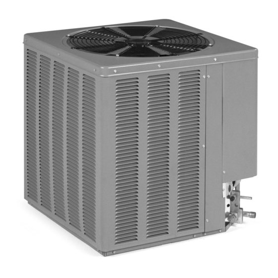
- Page 1 Installation and Operation Manual H J r RSE1318/1360-1A Split System Condensing Units...
- Page 2 13 SEER 1.5 TO 5 TON CONDENSING UNITS...
-
Page 3: Table Of Contents
TABLE OF CONTENTS Checking Product Received ........2 Electrical &... -
Page 4: Electrical & Physical Data
TABLE 1 ELECTRICAL AND PHYSICAL DATA Electrical Data Physical Data Fuse or HACR Outdoor Compressor Compressor Fan Motor Minimum Outdoor Outdoor Refrigerant Ship Circuit Breaker Cooling Phase-Frequency Coil Rated Load Locked Rotor Full Load Circuit Coil Coil Charge Weight Weight Capacity Voltage Area... -
Page 5: General
GENERAL WARNING The information contained in this manual has been prepared to assist in the proper THE MANUFACTURER’S WAR- installation, operation and maintenance of the air conditioning system. Improper RANTY DOES NOT COVER ANY installation, or installation not made in accordance with these instructions, can result DAMAGE OR DEFECT TO THE in unsatisfactory operation and/or dangerous conditions, and can cause the related AIR CONDITIONER CAUSED BY... - Page 6 CORROSIVE ENVIRONMENT The metal parts of this unit may be subject to rust or deterioration if exposed to a corrosive environment. This oxidation could shorten the equipment’s useful life. Corrosive elements include, but are not limited to, salt spray, fog or mist in seacoast areas, sulphur or chlorine from lawn watering systems, and various chemical conta- minants from industries such as paper mills and petroleum refineries.
-
Page 7: Unit Mounting
UNIT MOUNTING If elevating the condensing unit, either on a flat roof or on a slab, observe the following guidelines. • The base pan provided elevates the condenser coil 3/4” above the base pad. • If elevating a unit on a flat roof, use 4” x 4” (or equivalent) stringers positioned to distribute unit weight evenly and prevent noise and vibration. -
Page 8: Dimensions
FIGURE 1 AIR DISCHARGE: ALLOW DIMENSIONS 60” MINIMUM CLEARANCE. A-00008 AIR INLETS (LOUVERED PANELS) ALLOW 6” MINIMUM CLEARANCE SERVICE ACCESS ALLOW 24” CLEARANCE SEE DETAIL A 2" BASERAIL DIMENSIONAL DATA 13 SEER 36, 42, BASE PAN (BOTTOM VIEW) 18, 24 Cooling Capacity DO NOT OBSTRUCT DRAIN HOLES (SHADED). -
Page 9: Replacement Units
FIGURE 2 TIE-DOWN KIT ASSEMBLY DETAIL A REPLACEMENT UNITS To prevent failure of a new condensing unit, the existing evaporator tubing system must be correctly sized and cleaned or replaced. Care must be exercised that the expansion device is not plugged. Test the oil for acid. If positive, a suction line filter drier is mandatory. - Page 10 OUTDOOR UNIT INSTALLED ABOVE INDOOR COIL Keep the vertical separation between coils to a minimum. However, the vertical dis- tance can be as great as 120 feet with the condensing unit ABOVE the indoor coil. Use the following guidelines when installing the unit: DO NOT exceed 120 feet maximum vertical separation.
- Page 11 TABLE 3 VAPOR LINE LENGTH SIZE AND CAPACITY MULTIPLIER Cooling Capacity 7/8” I.D. Suction Line 3/4” I.D. Sweat 7/8” I.D. Sweat Sweat (4) Connection Size 5/8” O.D. Optional 3/4” O.D. Optional 7/8” O.D. Optional Suction Line Run Feet 3/4” O.D. Standard 7/8”...
- Page 12 TABLE 4 LIQUID LINE SIZE — OUTDOOR UNIT ABOVE INDOOR COIL LIQUID LINE SIZE - OUTDOOR UNIT ABOVE INDOOR COIL TOTAL LENGTH - (ft) Line Liquid Line Size Connection Model (Inch Size (Inch O.D.) I.D.) VERTICAL SEPARATION - (ft) 1/4* 5/16 5/16 1/4*...
-
Page 13: Evacuation Procedure
EVACUATION PROCEDURE Evacuation is the most important part of the entire service procedure. The life and efficiency of the equipment is dependent upon the thoroughness exercised by the serviceman when evacuating air and moisture from the line set and indoor coil. Air in the system causes high condensing temperatures and pressure, resulting in increased power input and non-verifiable performance. -
Page 14: Checking Refrigerant Charge
Electric resistance heaters can use volts x amps x 3.414 CFM = 1.08 x temp rise Gas furnaces can use BTUH CFM = ΔT x 1.08 An air velocity meter or airflow hood can give a more accurate reading of the sys- tem CFM. -
Page 15: Electrical Wiring
ELECTRICAL WIRING WARNING Field wiring must comply with the National Electric Code (C.E.C. in Canada) and TURN OFF ELECTRIC POWER AT any applicable local code. THE FUSE BOX OR SERVICE PANEL BEFORE MAKING ANY ELECTRICAL CONNECTIONS. GROUNDING ALSO, THE GROUND CONNEC- A grounding lug is provided near the contactor for a ground wire. -
Page 16: Field Installed Accessories
FIGURE 3 CONTROL WIRING FOR GAS OR ELECTRIC HEAT FOR TYPICAL GAS OR OIL HEAT FOR TYPICAL ELECTRIC HEAT TABLE 7 MAXIMUM SYSTEM CHARGE VALUES Charge Limit Model Compressor Without Size Model Number Crankcase Heat H21J14BABCA 7 lbs. H21J19BABCA 7 lbs. H21J24BABCA 7 lbs. -
Page 17: Service
LOW AMBIENT CONTROL (LAC) This component senses compressor head pressure and shuts the condenser fan off when the head pressure drops to approximately 175 PSIG. This allows the unit to build a sufficient head pressure at lower ambient in order to maintain system bal- ance and obtain improved capacity. -
Page 18: Trouble Shooting
TROUBLE SHOOTING In diagnosing common faults in the air conditioning system, it is useful to present the logical pattern of thought that is used by experienced technicians. The charts which follow are not intended to be an answer to all problems, but only to guide your thinking as you attempt to decide on your course of action. - Page 19 MECHANICAL CHECKS FLOW CHART Unit Running? Pressure problems? Go to Electrical Checks Flow Chart High Head Pressure Low Head Pressure Low Suction Pressure Dirty Condenser Coil Low on Charge Dirty Filters Inoperative Outdoor Fan Open IPR Valve Dirty Evaporator Overcharge Low Ambient Temperature Inadequate Airflow Recirculation of...
- Page 20 SUPERHEAT CALCULATION TABLE 8 TEMPERATURE PRESSURE CHART 1. Measure the suction pressure at the suction line service valve. TEMP R-22 2. Convert the suction pressure to saturated temperature. See Table 8. (Deg. F) PSIG 3. Measure the temperature of the suction line at the suction line service valve. -150 *29.4 4.
-
Page 21: Trouble Shooting Chart
TROUBLE SHOOTING CHART WARNING DISCONNECT ALL POWER TO UNIT BEFORE SERVICING. CONTACTOR MAY BREAK ONLY ONE SIDE. FAILURE TO SHUT OFF POWER CAN CAUSE ELECTRICAL SHOCK RESULTING IN PERSONAL INJURY OR DEATH. SYMPTOM POSSIBLE CAUSE REMEDY Unit will not run •... -
Page 22: Wiring Diagram
FIGURE 4 SINGLE-PHASE WIRING DIAGRAM... - Page 23 Design, specifications, performance data and materials subject to change without notice. 1900 Wellworth Ave., Jackson, Michigan 49203 • Ph. 517-787-2100 • Fax 517-787-9341 www.heatcontroller.com THE QUALITY LEADER IN CONDITIONING AIR 09/06...