Advertisement
Table of Contents
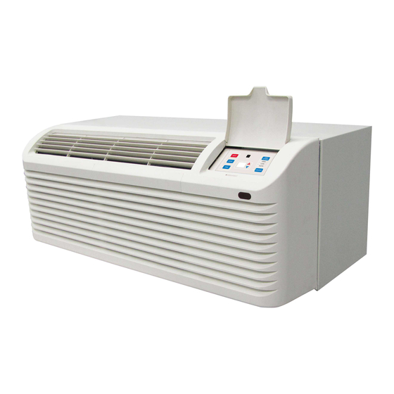
OWNER'S MANUAL
Packaged Terminal
Air Conditioners & Heat Pumps
Heat Controller • 1900 Wellworth Ave. • Jackson, MI 49203 • (517)787-2100 • www.heatcontroller.com
7,000-15,000 BTUH
Cooling with Electric Heat
PTAC07A130A
PTAC09A130A
PTAC12A130A
PTAC12A150A
PTAC15A150A
PTAC15A130A
Heat Pump with Electric Heat
PTHP07A130A
PTHP09A130A
PTHP12A130A
PTHP12A150A
PTHP15A150A
PTHP15A130A
Advertisement
Table of Contents

Related Manuals for Heat Controller PTAC07A130A


Summary of Contents for Heat Controller PTAC07A130A
- Page 1 Air Conditioners & Heat Pumps 7,000-15,000 BTUH Cooling with Electric Heat PTAC07A130A PTAC09A130A PTAC12A130A PTAC12A150A PTAC15A150A PTAC15A130A Heat Pump with Electric Heat PTHP07A130A PTHP09A130A PTHP12A130A PTHP12A150A PTHP15A150A PTHP15A130A Heat Controller • 1900 Wellworth Ave. • Jackson, MI 49203 • (517)787-2100 • www.heatcontroller.com...
-
Page 2: Table Of Contents
PACKAGED TERMINAL A/C OWNER’S MaNual Heat Controller CONTENTS THE FOLLOWING WARNINGS ARE VERY IMPORTANT FOR SAFETY. UNIT FEATURES ............2 PLEASE READ THEM CAREFULLY BEFORE INSTALLATION! INSTALLATION INSTRUCTION ........ 4 1. This air conditioner must be installed by a WIRING ..............8 certificated installer. -
Page 3: Unit Features
Heat Controller OWNER’S MaNual Packaged Terminal A/C UNIT FEATURES • High Pressure Protection - The unit will shut off automatically when the pressure in the system This unit has many features which are different than is over 638 psi and within 10 minutes, after the those found on conventional PTAC units. - Page 4 PACKAGED TERMINAL A/C OWNER’S MaNual Heat Controller ON position enables continuous fan for heating. The • Fan Motors Permanently Lubricated - All units default setting Is fan cycled for heating. have two fan motors for quiet operation and No. 8 -Fan CYC/CON for cooling ON position maximum operating efficiency.
-
Page 5: Installation Instruction
Heat Controller OWNER’S MaNual Packaged Terminal A/C INSTALLATION INSTRUCTIONS To ensure that the unit operates safely and efficiently, it must be installed, operated and maintained according to these installation and operating instructions and all local codes and ordinances or,in their absence, with the latest edition of the National Electric Code (or CEC for Canadian Installations). - Page 6 PACKAGED TERMINAL A/C OWNER’S MaNual Heat Controller Preparation of the Wall The sleeve should be installed during construction and lintels should be used to support the block above the wall sleeve. The sleeve can not support the load of bricks/ blocks.
-
Page 7: Chassis Installation
Heat Controller OWNER’S MaNual Packaged Terminal CHASSIS INSTALLATION IMPORTANT NOTES: 1. Remove the cabinet front from the chassis as 1. The unit is equipped with a rubber grommet described In Front Removal. mounted compressor. These grommets are factory 2. Insert the chassis into the wall sleeve. -
Page 8: Wiring
PACKAGED TERMINAL OWNER’S MaNual Heat Controller WIRING Operating Voltage Cord connection to a wall socket is not permitted for Unit Voltage Voltage Utilization Range 265V units. All 265V units must be hard wired using Rating Minimum Minimum the hard wire kit or make use of the plug in receptacle 230/208 in the standard subbase. -
Page 9: Operating Instructions (Accessory Optional)
Heat Controller OWNER’S MaNual Packaged Terminal OPERATING INSTRUCTIONS Fan Speed button Operation mode buttons Receiver of IR remote controller signal Press this button to Press these buttons to select select the fan speed on the unit mode heat, cool or high, low or auto. -
Page 10: Ventilation Control
PACKAGED TERMINAL OWNER’S MaNual Heat Controller VENTILATION CONTROL COOL / FAN / HEAT MODE OPERATION PROCEDURE The ventilation control lever is located at left side of Control panel: unit, behind front panel. • Press the ON/OFF button. NOTE: The vent door shipping tape must be removed •... -
Page 11: Maintenance And Cleaning
Heat Controller OWNER’S MaNual Packaged Terminal Discharge Air Flow WARNING 3. Remove the seven (7) screws which secure the HIGH VOLTAGE discharge air grille to the cabinet front. DISCONNECT ALL POWER BEFORE SERVICING OR INSTALLING THIS UNIT. MULTIPLE POWER SOURCES BE... - Page 12 PACKAGED TERMINAL OWNER’S MaNual Heat Controller 2. Pull the filter straight up and remove. Routine scheduled Maintenance 3. Clean filter with vacuum or with running water. To achieve continuing top performance and high Reverse this procedure to reinstall the filter.
-
Page 13: Normal Operating Sounds And Condition
Heat Controller OWNER’S MaNual Packaged Terminal Air sounds 4. Tilt the non-compressor side of the unit up no higher than 45 degrees and allow water to drain out the other The fan cycle switch sets the operational mode of the side of the unit. -
Page 14: Troubleshooting
PACKAGED TERMINAL OWNER’S MaNual Heat Controller TROUBLESHOOTING POSSIBLE CAUSES SOLUTIONS UNIT DOES NOT START • Check that plug is plugged securely in wall receptacle. • Unit may be unplugged Note: Plug has a test/reset button on it. Make sure that the plug has not tripped. - Page 15 Heat Controller OWNER’S MaNual Packaged Terminal A/C...
- Page 16 9/2014...