Kodak EKTAPRO 4020 Service Manual
Hide thumbs
Also See for EKTAPRO 4020:
- Service manual (135 pages) ,
- Quick reference manual (77 pages) ,
- Illustrated parts list (52 pages)

Related Manuals for Kodak EKTAPRO 4020


Summary of Contents for Kodak EKTAPRO 4020
-
Page 1: Service Manual
Publication No. SM 2547-1 03/98 SERVICE MANUAL for the KODAK EKTAPRO Slide Projector Model 4020, 5020, 7020, 9020, (9020/CINE) © Kodak AG, Stuttgart 1998 Kodak AG, Stuttgart 03/98... - Page 2 Kodak shall not be liable for any loss or damage, including consequential or special damages, resulting from the use of this information, even if loss or damage is caused by Kodak’s negligence or other fault.
-
Page 3: Table Of Contents
Every Day ........................... 1-2 During Maintenance and Repair ....................1-2 1. GENERAL INFORMATION ......................1-3 Service Tools ............................1-3 For Models 4020/5020/7020/9020 and 9020/CINE ................1-3 Safety Precaution..........................1-4 Safety Check ............................1-5 2. INTRODUCTION ..........................2-1 Projector Models ..........................2-2 EKTAPRO Model 4020....................... - Page 4 P-Bus / RS 232 “IN”........................2-14 P-Bus / RS 232 “OUT”......................2-14 ACCESSORY SLOT......................... 2-15 OEM ACCESSORIES ........................2-16 COPYWRITE..........................2-16 SLIDE SYNCHRONIZER ADAPTER by KODAK AUSTRALIA..........2-17 ADAPTER by MÜWO ....................... 2-18 ADAPTERS by MAYER & ZELLER..................2-19 ADDRESSES ............................. 2-20 CONTROL SYSTEMS......................2-20 SOFTWARE for direct PC CONTROL..................
- Page 5 UPPER HOUSING..........................4-1 BUTTONS and COVER PLATES ....................... 4-2 Assembly ............................ 4-3 CENTER HOUSING ........................... 4-4 FAN, KEYBOARD PCB and TRAY MOTION PCB................4-8 BACK PANEL PCB........................... 4-10 TRANSFORMER, POWER SUPPLY PCB and BACK PLATE ASSEMBLY ........4-11 Kodak AG, Stuttgart 03/98...
- Page 6 LOWER HOUSING........................... 4-25 DUAL LAMP MODULE ........................4-26 DUAL LAMP MODULE......................4-29 Lubrication ............................4-30 5. DIAGNOSTICS ..........................5-1 Diagnostic Overview EKTAPRO 4020/5020/7020/9020 and 9020/CINE ........... 5-1 Preparation ............................5-3 Conditions:..........................5-3 No Function............................5-4 Switch on Procedure Problems......................5-9 Lamp Problems EP 4020/5020/7020/9020 and 9020/CINE .............
- Page 7 6. Projector Checking ......................... 6-1 Slide Transport Problems ........................6-1 Slide jam (all models) ......................... 6-2 CODER DISK ............................. 6-2 7. MAINTENANCE ..........................7-1 Maintenance Intervals......................... 7-1 Maintenance Procedure........................7-1 Cleaning.............................. 7-1 Ultrasonic cleaning ........................7-2 Lubrication ............................7-3 Kodak AG, Stuttgart 03/98...
- Page 8 Service Manual SM 2547-1 blank page 03/98 VIII Kodak AG, Stuttgart...
-
Page 9: Electrostatic Discharge
ESD protected sites. If you work around electronic equipment, keep static generators like plastic trash bags away from sensitive components. Observe ESD guidelines everyday. (See the following sections for special tips). Remember, effective ESD control is everyone’s responsibility: Kodak AG, Stuttgart 03/98... -
Page 10: Every Day
Use a portable grounding mat if you cannot repair components at an ESD-protected workstation. (Kodak’s Customer Equipment Services Division can help you in set up ESD-protected workstations.) . Use protective packaging when you transport components from one area to another. Transparent antistatic bags, available from a variety of manufacturers, shield the components from further damage. -
Page 11: General Information
SM 2547-1 Service Manual 1. GENERAL INFORMATION Service Tools Use the following tools to repair a KODAK EKTAPRO Slide Projector: TORX Screw Driver size 206 TORX Screw Driver size 210 TORX Screw Driver size 215 or TORX bits TL-3255 TORX Screw Driver size 220... -
Page 12: Safety Precaution
Make sure that the requirements of UL 122 - Splices and Connection - paragraph 13.10 and EN 60 950, section 4.39 are observed. When replacing AC primary components, such as wires, sockets or capacitors , wrap the ends of the wire completely around the terminal before soldering. 03/98 Kodak AG, Stuttgart... -
Page 13: Safety Check
= 7 mA Interfaces Models 7020 and 9020 have an accessory slot. The 7/12pin module from Kodak is safety tested, and has approval from VDE and other institutions. If an OEM module is installed, inform the customer: the OEM is responsible for the safety and function of the module. - Page 14 Service Manual SM 2547-1 blank page 03/98 Kodak AG, Stuttgart...
-
Page 15: Introduction
This new feature allows the future use of other equipment manufacturers Projector systems and accessories. The Models 4020, 5020, 7020 and 9020 are equipped with an RS 232 interface (P-Bus). This bus allows communication with a computer and multi Projector shows in a new way. The P-Bus can also be used for Service Diagnostics. -
Page 16: Projector Models
Service Manual SM 2547-1 Projector Models EKTAPRO Model 4020 figure 2-1 Features and Functions: Line voltages 120/220/230/240V or 100/220VAC can be select with an external VOLTAGE SELECTOR Line frequency 50/60 Hz Power consumption 380 W Dual Lamp Module Extra Bright:... -
Page 17: Ektapro Model 4020
SM 2547-1 Service Manual EKTAPRO Model 4020 Adjustable Tray Motion Tool PN 622 0454 has to used on Projectors from SN 85 xxx and above Manual elevator mechanism : Two height adjustment feet are attached on the front side of the... -
Page 18: Ektapro Model 5020
Service Manual SM 2547-1 EKTAPRO Model 5020 figure 2-2 Features and Functions: All features and functions of Model 4020 Additional: AUTO FOCUS Each slide will be focused, independent of the slide mount Timer Slide change can be set from 1 up to 60 sec. -
Page 19: Ektapro Model 7020
SM 2547-1 Service Manual EKTAPRO Model 7020 figure 2-3 Features and Functions: All features and functions as Model 4020. Additional features: Application Slot for Kodak and OEM ADAPTERS Bus CONNECTORS (RS232) : IN (female) and OUT (male) Address Switch 16 addresses can be selected... -
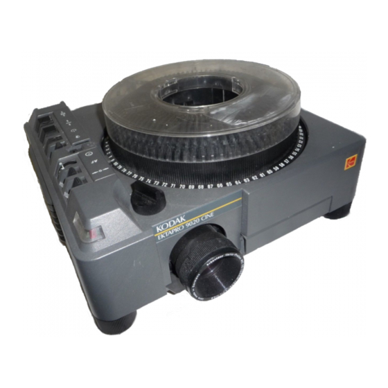
Page 20: Ektapro Model 9020
Switching the projector on again the slide tray will run into that position after the initialization procedure. If the timer is switched on at that time a soft dissolve will be started immediately. New parts (NAMEPLATE and MICROCONTROLLER) see Illustrated parts list. 03/98 Kodak AG, Stuttgart... -
Page 21: Overview
PRESENTATION BUS “IN” PRESENTATION BUS “OUT” RANDOM ACCESS EXTERNAL DIAGNOSTICS 12/7-PIN MODULE SLIDE SYNCHRONIZER (1000Hz) TWIN SOCKET CABLE REMOTE IR REMOTE SYSTEM RA IR REMOTE SYSTEM RA/LP X = Standard Feature O = Accessory not possible Kodak AG, Stuttgart 03/98... -
Page 22: Accessories
CABLE REMOTE CAT No. 712 1080 figure 2-6 HEAT ABSORBING GLASS with CLIP (not installed in Model 3020) CAT No. 717 7140 (6mm thick) CAT No. 717 7157 (3mm thick) see NEWSLETTER #3/MAY/1996 page 5 figure 2-7 03/98 Kodak AG, Stuttgart... -
Page 23: Condenser Kit 4X4 (With Clip)
SM 2547-1 Service Manual CONDENSER KIT 4X4 (with CLIP) CAT No. 714 4967 figure 2-8 IR REMOTE System RA (with Random Access) CAT No. 712 1072 complete with RECEIVER and TRANSMITTER RECEIVER figure 2-9 TRANSMITTER figure 2-10 Kodak AG, Stuttgart 03/98... -
Page 24: Ir Remote System Ra/Lp (Laser Pointer)
CAT No. 712 1064 complete with RECEIVER TRANSMITTER RECEIVER as use with IR REMOTE System RA. figure 2-11 12/7-PIN MODULE CAT No. 712 5875 Int. Ext. figure 2-12 LENS SUPPORT CAT No. 715 1335 figure 2-13 03/98 2-10 Kodak AG, Stuttgart... -
Page 25: 12/7-Pin Adapter Cable
SM 2547-1 Service Manual 12/7-PIN ADAPTER CABLE CAT No. 712 5883 figure 2-14 TWIN SOCKET ADAPTER CAT No. 712 5909 see NEWSLETTER #3/MAY/1996 page 7 figure 2-15 Kodak AG, Stuttgart 2-11 03/98... -
Page 26: Slide Synchronizer
LAMPS Catalog No. Description Lifetime 145 2259 EXR 82V/300 W life time about 35 hours 147 7678 EHS 82V/300 W life time about 70 hours 145 2143 EXY 82V/250 W life time about 200 hours 03/98 2-12 Kodak AG, Stuttgart... -
Page 27: Specification
Type Mini DIN 12 VDC Signal 1 (LSB) Signal 2 Signal 3 Signal 4 Signal 5 (MSB) Interrupt 12 V DC = (viewed from front ) average value between 7.2 and 14.5 V DC figure 2-16 Kodak AG, Stuttgart 2-13 03/98... -
Page 28: P-Bus / Rs 232 "In
2-17 P-Bus / RS 232 “OUT” PIN No. Signal Connected to 4 and 6 Transmit Data (TxD)v Receive Date (RxD) Connected to 1 and 6 Signal Ground Connected to 1 and 4 figure 2-18 03/98 2-14 Kodak AG, Stuttgart... -
Page 29: Accessory Slot
12V DC 200mA max. 34V DC 750mA max. figure 2-19 a 10 26V AC_N 750mA max. SLC (I C Clock) PLL_DISS SLOT_232_T (TTL-Level) SLOT_DIS SLOT_B SL_DISS not used VSS 12 (Ground) VSS 34 (Ground) b 10 26V AC_L Kodak AG, Stuttgart 2-15 03/98... -
Page 30: Oem Accessories
The advantage is that the Adapter and Projector can be separated. In addition, the use of the EKTAPRO Remote Transmitter is possible without disconnecting the Adapter. CABLE USE If no IR receiver is available the Adapter can be plugged with the fixed installed cable to the remote socket. 03/98 2-16 Kodak AG, Stuttgart... -
Page 31: Slide Synchronizer Adapter By Kodak Australia
SLIDE SYNCHRONIZER ADAPTER by KODAK AUSTRALIA Kodak Australia offers an own solution of a slide synchronizer adapter. This unit is built in the IR Receiver housing and is therefor directly to be plugged onto the remote socket. A 6pin socket is built into the housing. -
Page 32: Adapter By Müwo
Control. A 6pin socket provides connection with external devices which are traditional AV cassette recorders, S-AV Timer and speaker desks. Even if any devices are connected, the remote still works. Professional AV Cassette Recorder Speaker´s Desk EKTAPRO Remote Control S-AV Timer with built in Slide Synchronizer Adapter figure 2-22 03/98 2-18 Kodak AG, Stuttgart... -
Page 33: Adapters By Mayer & Zeller
Timer for controlling the EKTAPRO Projectors. The timer is built into the EKTAPRO Cable Remote Control. This a quite sophisticated solution and an interesting offer for those who intend buying a cable remote. For further details contact the company. Kodak AG, Stuttgart 2-19 03/98... -
Page 34: Addresses
Stumpfl Rudigierstraße 8, A-4701 Bad Schallerbach Austria Tel: (0043) 7249 2811 Fax: (0043) 7249 2811 18 Zygo Systems Limited 48 Fallowfields Bicester Oxon OX67Qs UK Tel: (0044) 869 248 261 Fax: (0044) 869 248 260 03/98 2-20 Kodak AG, Stuttgart... -
Page 35: Software For Direct Pc Control
(0041) 61681 4343 Fax: (0041) 61681 3907 Müwo electronic In den Maltwiesen 11, 72379 Hechingen-Stetten Germany Tel: (0049) 7471 15830 Wintron GmbH Egilolfstraße 70, 70599 Stuttgart Germany Tel: (0049) 711 4567 258 (0049) 711 4567 267 Kodak AG, Stuttgart 2-21 03/98... - Page 36 Service Manual SM 2547-1 blank page 03/98 2-22 Kodak AG, Stuttgart...
-
Page 37: Theory Guide
All functions of the projector are controlled by the MICROCONTROLLER ( MC68HC016B with 16k ROM) on the MASTER PCB. The controlling software is loaded in the 16k ROM of the MICROCONTROLLER for Models 4020 - 9020 and 9020/CINE. Located around the MICROCONTROLLER on the MASTER PCB there are the inputs, outputs and drivers for the sensors, LAMP, MOTOR´s and other functions. - Page 38 Service Manual SM 2547-1 figure 3-1 03/98 Kodak AG, Stuttgart...
-
Page 39: Microcontroller Unit
Microcontroller Unit The main device on the MASTER PCB is the 16-bit MICROCONTROLLER unit MC68HC05B16 from MOTORola for the models EKTAPRO 4020 - 9020 and 9029/CINE This MICROCONTROLLER has a microprocessor, timer, memory, analog/ digital converter and input/output ports on one chip. Compared to a standard processor, where for each item a peripheral IC is necessary. -
Page 40: Description Of Functions
POWER REGULATION PCB The TRANSFORMER supplies the following voltages: Primary voltage outputs: 92/81 VAC LAMP voltage for Models 4020 - 9020 and 9020/CINE (SOFTWARE CONTROLLED LAMP CURVE) Safety Extra Low Voltage outputs: 10 VAC for +5V DC and +12V DC... - Page 41 SM 2547-1 Service Manual figure 3-3 Kodak AG, Stuttgart 03/98...
-
Page 42: Switch On / Initialize Procedure
Power LED Blinking Slide in Gate Sensor actuated If the SLIDE IN GATE SENSOR is actuated, the SHUTTER opens. Write the Failure into Memory Open Shutter Autofocus On Projector does not Operate Projector Ready for Operation figure 3-4 03/98 Kodak AG, Stuttgart... -
Page 43: Slide Change Sequence
Projector does not Open Shutter operate When a TIMER is in use, a slide advance forward is done each time after the selected interval is reached (Model´s 4020, 7020 external Timer timer, Model 5020, 9020 and 9020/CINE internal timer). activated The slide is projected. -
Page 44: Tray Motion
The DIRECTION + STEP SENSOR is a special optical device which generates two independent output signals: step pulses (count signal for the MICROCONTROLLER to calculate the tray position) direction signal (low signal for forward steps and high signal for reverse steps) 03/98 Kodak AG, Stuttgart... -
Page 45: Tray Motion Sequence
Go To Zero Position Projector Status: - Energized Signal from: - P-Bus (Model´s 4020 and 5020 input only) - Auto Zero (Model 9020 and 9020/CINE) The MICROCONTROLLER selects shortest distance to the zero position. The TRAY MOTOR is energized. - Page 46 Slide LIFTER down Projector stops at the ZERO POSITION. inoperable Slide projected The MICROCONTROLLER sets the next position into memory. The SLIDE LIFTER Down procedure starts. For details, see Slide Change Sequence. figure 3-8 03/98 3-10 Kodak AG, Stuttgart...
-
Page 47: Lamp Control
LAMP. The LED’s are located on the BACK PANEL. The Models 4020 - 9020 and 9020/CINE have a memory. This memory is storing the the current used lamp as long as the lamp is defective. That means the mirror of the DUAL LAMP MODULE do not change his position after a new lamp is inserted. -
Page 48: C) Lamp Protection
Service Manual SM 2547-1 b) LAMP setting Models 4020 - 9020 and 9020/CINE: a) Through the LAMP SWITCH or P-Bus The settings of the LAMP are change by using the LAMP dimming function through the TRIAC DISSOLVE LOGIC. The phase cut position for LOW is 75% of HIGH . -
Page 49: E) Lamp Dimming
Service Manual e) Lamp Dimming The LAMP DIMMING FUNCTION is installed in Model 4020 - 9020. It is used for dissolving for Economy and Standard LAMP settings. The main devices for dimming are the TRIAC, TRIAC CONTROL and Zero_Cross circuit on the POWER REGULATION PCB, the dissolve logic and the MICROCONTROLLER (MC) on the MASTER PCB. - Page 50 These steps can be used to create a linear LAMP brightness change. A lookup table is used in the MICROCONTROLLER software. This table contains the corresponding phase cut value for each one of the 1000 steps for a linear brightness setting. figure 3-11 03/98 3-14 Kodak AG, Stuttgart...
-
Page 51: Focus
2. Use the FOCUSING BUTTONS either on the KEYBOARD of the PROJECTOR or on the REMOTE CONTROL. In this case the LENS and the LENS CARRIER are moving together. The focus range is limited, and depend on the ECCENTRIC of the FOCUS MOTOR (approx. 8mm / 0.3 in.). figure 3-12 Kodak AG, Stuttgart 3-15 03/98... -
Page 52: Auto Focus
If glassless slide frames are in use, it could be, that the borders of the projected image are out of focus. It depends on the IR-Beam which is only sensing the center of the slide. figure 3-13 03/98 3-16 Kodak AG, Stuttgart... -
Page 53: P-Bus
All the Models are equipped with the P-Bus feature. The Models 4020 and 5020 has only an Input Bus, Models 7020 and 9020 and 9020/CINE an IN/OUT Bus. The P-Bus (Presentation Bus) is a serial asynchronous data transmission interface which uses the RS 232 / V.24/ V.28 standard. -
Page 54: Command Structure
An example of command modes is: parameter mode set/reset mode direct mode status request mode In this mode, the projector returns (10 bit) data. This mode can be used for diagnostics purposes. Details can be obtained from special marketing literature. 03/98 3-18 Kodak AG, Stuttgart... -
Page 55: Accessory Slot
Voltage Supply for accessory slot modules. See 2.4 CONNECTORS. Special Control lines SLOT_A, SLOT_B, SLOT_C All lines are connected to ground means 12/7 PIN adapter present, PROJECTOR LAMP off, waiting for dissolve pulses on SL_DISS line all high, no ACCESSORY installed Kodak AG, Stuttgart 3-19 03/98... -
Page 56: Remote Control
5 bit data. For example: Slide No. 3 = decimal 20 20 23 , binary 10100 10100 10111 Slide No. 140 = decimal 21 24 20 , binary 10101 11000 10100 03/98 3-20 Kodak AG, Stuttgart... - Page 57 1 1 0 1 0 1 1 0 1 1 Key 7 1 1 1 0 0 Key 8 1 1 1 0 1 Key 9 Key 0 1 0 1 0 0 Internal Clear Enter 3 words internal Kodak AG, Stuttgart 3-21 03/98...
- Page 58 Service Manual SM 2547-1 blank page 03/98 3-22 Kodak AG, Stuttgart...
-
Page 59: Disassembly/Assembly
SM2547-1 Service Manual 4. DISASSEMBLY/ASSEMBLY UPPER HOUSING Remove the LAMP MODULE. Remove the KNOB. Remove the 4 SCREWS. Remove the UPPER HOUSING. KNOB UPPER HOUSING BUTTONS ( 3) LAMP MODULE LABEL SCREWS (4) figure 4-1 Kodak AG, Stuttgart 03/98... -
Page 60: Buttons And Cover Plates
Loosen the HOLDING CLIP and remove the large COVER PLATE. If needed, change the 5 BUTTONS. small COVER PLATE BUTTONS (3) BUTTONS (5) large COVER PLATE figure 4-3 If necessary, replace the WINDOW and/or MODEL LABEL. WINDOW MODEL LABEL CORPORATE SYMBOL figure 4-2 03/98 Kodak AG, Stuttgart... -
Page 61: Assembly
SM2547-1 Service Manual Assembly NOTE Please note the positions of the 3 BUTTONS and the SWITCH on the KEYBOARD PCB. BUTTONS (3) figure 4-4 SWITCH POSITION on the KEYBOARD PCB figure 4-5 Kodak AG, Stuttgart 03/98... -
Page 62: Center Housing
Remove the SPRING and the ZERO LEVER. See figure 4-7. Remove the 8 RETAINERS and 8 ROLLERS. See figure 4-7. Remove the DRIVE RING. See figure 4-7. Remove the 3 SHAFT ROLLERS and the 3 BEARING ROLLERS. See figure 4-7. 03/98 Kodak AG, Stuttgart... - Page 63 . Remove the 4 SCREWS. . Remove the CENTER HOUSING. . Remove the 2 SCREWS and the MOTOR. . Remove the SCREW and the LATCH GEAR WHEELS CENTER HOUSING CODER DISK SCREWS (4) MOTOR LATCH/SCREW SCREWS (2) figure 4-8 Kodak AG, Stuttgart 03/98...
- Page 64 . During disassembly and assembly of the CENTER HOUSING, place the TRAY RELEASE LEVER into the position as shown below. TRANSPORT RELEASE LEVER IMPORTANT: Take care of this positions! Incorrect positioning can cause transport failures. figure 4-9 03/98 Kodak AG, Stuttgart...
- Page 65 HOUSING ADAPTER SOCKET figure 4-10 . Check that the POWER SUPPLY PCB is positioned in the GUIDE of the CENTER HOUSING. GUIDE of CENTER HOUSING GUIDE of CENTER HOUSING POWER SUPPLY PCB CENTER HOUSING figure 4-11 Kodak AG, Stuttgart 03/98...
-
Page 66: Fan, Keyboard Pcb And Tray Motion Pcb
Remove the CENTER HOUSING. See page 4-4. Disconnect the FAN MOTORS. Remove the FAN. Disconnect the KEYBOARD PCB. Disconnect the TRAY MOTION PCB. figure 4-12 NOTE: Do not clean the FAN with compressed air because the rotary wings would be demaged! 03/98 Kodak AG, Stuttgart... - Page 67 SM2547-1 Service Manual NOTE When placing the FAN in the LOWER HOUSING, insert the FAN as shown in figure 4-13. FOAM GUIDE LOWER HOUSING figure 4-13 GUIDE HOLE for FAN LOWER HOUSING GUIDE for figure 4-14 Kodak AG, Stuttgart 03/98...
-
Page 68: Back Panel Pcb
Service Manual SM2547-1 BACK PANEL PCB Remove the UPPER HOUSING. See page 4-1. Remove the CENTER HOUSING. See page 4-4. Remove the FAN. See page 4-9. Remove the BACK PANEL PCB. FUSE HOLDER ASSEMBLY figure 4-15 03/98 4-10 Kodak AG, Stuttgart... -
Page 69: Transformer, Power Supply Pcb And Back Plate Assembly
Disconnect POWER SUPPLY PCB from the MASTER BOARD PCB. Remove the TRANSFORMER and the BACK PLATE ASSEMBLY. If needed, install new assemblies. SCREW (4) TRANSFORMER POWER SUPPLY CONNECTORS(P3) NEUTRAL WIRES LAMP HOUSING ASSEMBLY BACK PLATE ASSEMBLY figure 4-16 Kodak AG, Stuttgart 4-11 03/98... -
Page 70: Mechanism Frame And Lens Mount
Lift the MECHANISM FRAME and LENS MOUNT and remove the 3 CONNECTORS J 3, J 10, J 12. See page 4-19. SCREW (4) SCREW AF PCB TRANSFORMER LENS MOUNT NEUTRAL WIRE MECHANISM FRAME figure 4-17 03/98 4-12 Kodak AG, Stuttgart... -
Page 71: Lens Mount
Remove the 4 SCREWS and the TRANSFORMER. See page 4-11. Remove the MECHANISM FRAME and LENS MOUNT. See page 4-12. Remove the SPRING. Remove the LENS MOUNT from the MECHANISM FRAME. LENS MOUNT SCREW (3) MECHANISM FRAME SPRING figure 4-18 Kodak AG, Stuttgart 4-13 03/98... - Page 72 Remove the SCREW and the MAGNET. . Remove the 3 SCREWS, the AUTO FOCUS RETAINER and the SPRING. SPRING LENS MOUNT MAGNET SHAFT SHOCK ABSORBER SHUTTER PLATE SCREW SCREW SCREW SCREW (3) RETAINER AF ASSEMBLY figure 4-19 03/98 4-14 Kodak AG, Stuttgart...
- Page 73 If the SHUTTER has to be replaced and the COVER MECHANISM FRAME is provided with the small recess, the SHUTTER has to be bent first. Otherwise it might touch the COVER MECHANISM FRAME. SHUTTER COVER MECHANISM FRAME GROOVE figure 4-20 Kodak AG, Stuttgart 4-15 03/98...
-
Page 74: Retainer Af Assembly
Rotate the LEVER for the SHUTTER out at the MAGNET. Remove the 3 SCREWS, the RETAINER AF ASSEMBLY, and the SPRING. See page 4-14. Remove the 2 PRISM COVER and the 2 PRISMS. PRISM COVER (2) PRISM (2) TRANSMITTER PCB SCREW (3) figure 4-21 03/98 4-16 Kodak AG, Stuttgart... - Page 75 SM2547-1 Service Manual . Remove the SCREW, the TRANSMITTER PCB, and the TRANSMITTER COVER. . Remove the 2 SCREWS and the RECEIVER PCB. SCREW (3) RECEIVER PCB figure 4-22 Kodak AG, Stuttgart 4-17 03/98...
-
Page 76: Mechanism Frame
Remove the MECHANISM FRAME and LENS MOUNT. See page 4-12. Remove the SPRING and LENS MOUNT. See page 4-13. Remove the 2 SCREWS, 2 WASHERS and the COVER MECHANISM FRAME. MECHANISM FRAME MECHANISM FRAME COVER SCREW (2) WASHER (2) figure 4-23 03/98 4-18 Kodak AG, Stuttgart... - Page 77 Remove the SPRING, SLIDE REGULATION LEVER and the CAM. NOTE After the assembly of the parts, align the CAM so that the SLIDE LIFTER is in the lowest position. SPRING SLIDE REGULATION LEVER SPRING TRAY RELEASE LEVER LEVER SPRING SLIDE LIFTER figure 4-24 Kodak AG, Stuttgart 4-19 03/98...
- Page 78 Remove the 2 SCREWS, the CAM and the SHUTTER SENSOR ASSEMBLY. PRESSURE PAD SCREW (2) SPRING CAM and SHUTTER SENSOR ASSEMBLY LEVER SPRING figure 4-25 . Remove the 2 SCREWS and the MOTOR. SCREW (2) MOTOR figure 4-26 03/98 4-20 Kodak AG, Stuttgart...
-
Page 79: Auto Focus Pcb And Focus Motor
Remove the 4 SCREWS and the TRANSFORMER. See page 4-11. Remove the MECHANISM FRAME and LENS MOUNT. See page 4-12. Remove the SPRING, the FOCUS MOTOR and the RUBBER PAD. FOCUS MOTOR SPRING RUBBER PAD figure 4-27 Kodak AG, Stuttgart 4-21 03/98... -
Page 80: Master Board Pcb
Remove the MECHANISM FRAME and LENS MOUNT. See page 4-12. Disconnect all CONNECTORS from the MASTER PCB. See page 4-23: Remove the SCREW and the COVER. Remove the MASTER PCB. MICROCONTROLLER COVER MASTER BOARD PCB SCREW figure 4-28 03/98 4-22 Kodak AG, Stuttgart... -
Page 81: Master Board Pcb Connectors
During the assembly take care that all CONNECTORS are correctly plugged in! PLCC PIN-GRID SOCKET BACK PANEL PCB MIRROR MOTOR KEYBOARD PCB ACCESSORY SLOT AUTO FOCUS PCB CAM and SHUTTER SENSOR FOCUS MOTOR SLIDE LIFT MOTOR TRANSPORT MOTOR POWER SUPPLY PCB SHUTTER SOLENOID TRAY MOTION PCB Kodak AG, Stuttgart 4-23 03/98... -
Page 82: Microcontroller
MASTER PCB. When assembling note the beveled edge of the MICROCONTROLLER and the PLCC/PIN-GRID SOCKET. Install these edges together. MICROCONTROLLER PLCC EXTRACTOR TOOL (TL 4430) COVER SCREW NOTE The MICROCONTROLLER is installed in a PLCC-Socket. 03/98 4-24 Kodak AG, Stuttgart... -
Page 83: Lower Housing
Remove the 2 ELEVATOR RETAINERS, the right and left ELEVATOR KNOB, the right and left ELEVATOR and the 2 RUBBER FEET. LAMP HOUSING ASSEMBLY SCREW (2) ELEVATOR RETAINER (2) ELEVATOR KNOB (2) HANDLE ELEVATOR (2) RUBBER FOOT (2) figure 4-29 Kodak AG, Stuttgart 4-25 03/98... -
Page 84: Dual Lamp Module
Lift the EJECTOR LEVER . The defective LAMP will eject from the LAMP SOCKET ASSEMBLY. LAMP SCREW (3) WASHER (2) LAMP SOCKET ASSEMBLY EJECTOR LABEL EXTRA BRIGHT figure 4-30 Remove the CLIP and the CONDENSER LENS. CLIP CONDENSER LENS figure 4-31 03/98 4-26 Kodak AG, Stuttgart... - Page 85 Remove the GRILL PLATE, the AIR EXHAUST PLATE, the HOOK, the SPRING and the LAMP MODULE LABEL. SCREW (3) WASHER (2) LAMP HOUSING HOOK SPRING LAMP MODULE LABEL AIR EXHAUST PLATE GRILL PLATE figure 4-32 Kodak AG, Stuttgart 4-27 03/98...
- Page 86 SM2547-1 Remove the 2 EJECTORS. Remove the SPRING - Model 4020, 5020, 7020 ,9020 and 9020/CINE. Remove the MIRROR, the SPRING and the MIRROR HOLDER. Remove the MOTOR, the CIRCLIP and the SINGLE or DUAL LAMP SOCKET ASSEMBLY from the PLUG.
-
Page 87: Dual Lamp Module
The SPRING in the DUAL LAMP MODULE has to be mounted without tension between the MIRROR and the MOTOR. SPRING MOTOR figure 4-34 Lubrication Use the lubricant BARRIERTA L 25 DL (50g) No. 558 1960. Grease all arrow marked spots. MECHANISM FRAME figure 4-35 Kodak AG, Stuttgart 4-29 03/98... - Page 88 Service Manual SM2547-1 figure 4-36 LENS MOUNT GLIDING SURFACE figure 4-37 03/98 4-30 Kodak AG, Stuttgart...
-
Page 89: Diagnostics
SM 2547-1 Service Manual 5. DIAGNOSTICS Diagnostic Overview EKTAPRO 4020/5020/7020/9020 and 9020/CINE Kodak AG, Stuttgart 03/98... - Page 90 Service Manual SM 2547-1 03/98 Kodak AG, Stuttgart...
-
Page 91: Preparation
Ensure that line voltage does not vary more than +/- 5 % from the selected value on the projector. Insert a LAMP MODULE with a proper LAMP. Slide tray (80/140) with slide LENS (standard) Personal Computer / Lap top Interface Cable 9 PIN (Plug / socket) Kodak AG, Stuttgart 03/98... -
Page 92: No Function
Service Manual SM 2547-1 No Function 03/98 Kodak AG, Stuttgart... - Page 93 SM 2547-1 Service Manual see figure on page 28 Kodak AG, Stuttgart 03/98...
- Page 94 Service Manual SM 2547-1 see figure on page 28 03/98 Kodak AG, Stuttgart...
- Page 95 SM 2547-1 Service Manual Kodak AG, Stuttgart 03/98...
- Page 96 Service Manual SM 2547-1 03/98 Kodak AG, Stuttgart...
-
Page 97: Switch On Procedure Problems
SM 2547-1 Service Manual Switch on Procedure Problems Kodak AG, Stuttgart 03/98... - Page 98 Service Manual SM 2547-1 03/98 5-10 Kodak AG, Stuttgart...
- Page 99 SM 2547-1 Service Manual Kodak AG, Stuttgart 5-11 03/98...
-
Page 100: Lamp Problems Ep 4020/5020/7020/9020 And 9020/Cine
Service Manual SM 2547-1 Lamp Problems 4020/5020/7020/9020 and 9020/CINE 03/98 5-12 Kodak AG, Stuttgart... - Page 101 SM 2547-1 Service Manual (figure 3-11 and page 5-28) Kodak AG, Stuttgart 5-13 03/98...
- Page 102 Service Manual SM 2547-1 03/98 5-14 Kodak AG, Stuttgart...
- Page 103 SM 2547-1 Service Manual Kodak AG, Stuttgart 5-15 03/98...
- Page 104 Service Manual SM 2547-1 03/98 5-16 Kodak AG, Stuttgart...
-
Page 105: Mirror Position
Use the option “Adjust Brightness” from the Service Software TL-4575 to dim the PROJECTOR LAMP. There is a range from “0" (dark) to ”1000" (bright), in steps of 10 units. With the “Reset” command in the main menu the original brightness can be reset. Kodak AG, Stuttgart 5-17 03/98... -
Page 106: Switch On Procedure
Service Manual SM 2547-1 Switch On Procedure 03/98 5-18 Kodak AG, Stuttgart... -
Page 107: Switch On Procedure Complete - No Keyboard Function
SM 2547-1 Service Manual Switch On Procedure complete - No Keyboard Function Kodak AG, Stuttgart 5-19 03/98... -
Page 108: No Function With Remote Control
Service Manual SM 2547-1 No function with REMOTE CONTROL IR Remote Control 03/98 5-20 Kodak AG, Stuttgart... - Page 109 SM 2547-1 Service Manual Kodak AG, Stuttgart 5-21 03/98...
- Page 110 Service Manual SM 2547-1 03/98 5-22 Kodak AG, Stuttgart...
-
Page 111: Cable Remote
SM 2547-1 Service Manual Cable Remote Kodak AG, Stuttgart 5-23 03/98... -
Page 112: No Slide Transport Forward/Reverse And Other Projection Problems
Service Manual SM 2547-1 No Slide Transport forward/reverse and other projection problems 03/98 5-24 Kodak AG, Stuttgart... -
Page 113: Shutter Problems
SM 2547-1 Service Manual Shutter Problems Kodak AG, Stuttgart 5-25 03/98... - Page 114 Service Manual SM 2547-1 see figure on page 28 03/98 5-26 Kodak AG, Stuttgart...
-
Page 115: Fan Problems
SM 2547-1 Service Manual Fan Problems Kodak AG, Stuttgart 5-27 03/98... - Page 116 Service Manual SM 2547-1 03/98 5-28 Kodak AG, Stuttgart...
-
Page 117: Slide Obstruction In Slide Tray
SLIDE LIFT LEVER. Check the CENTER HOUSING for damaged parts such as: DRIVE RING GEAR WHEELS CODER DISK Inspect whether the parts are complete. Are there damaged or broken teeth on the wheels? If so, replace them. Kodak AG, Stuttgart 5-29 03/98... -
Page 118: Wrong Transport Step By 80/140 Slide Tray
Service Manual SM 2547-1 Wrong Transport Step by 80/140 SLIDE TRAY 03/98 5-30 Kodak AG, Stuttgart... - Page 119 SM 2547-1 Service Manual Kodak AG, Stuttgart 5-31 03/98...
-
Page 120: No Focus Actuation
Service Manual SM 2547-1 No Focus Actuation 03/98 5-32 Kodak AG, Stuttgart... - Page 121 SM 2547-1 Service Manual Kodak AG, Stuttgart 5-33 03/98...
-
Page 122: No Standby Function
Service Manual SM 2547-1 No Standby Function 03/98 5-34 Kodak AG, Stuttgart... - Page 123 SM 2547-1 Service Manual Communication Trouble 4020/5020/7020/9020 and 9020/CINE Kodak AG, Stuttgart 5-35 03/98...
- Page 124 Service Manual SM 2547-1 03/98 5-36 Kodak AG, Stuttgart...
- Page 125 SM 2547-1 Service Manual Kodak AG, Stuttgart 5-37 03/98...
-
Page 126: Auto Focus 5020/9020 And 9020/Cine: No Auto Focus Function
Service Manual SM 2547-1 AUTO FOCUS 5020,9020 and 9020/CINE: No AUTO FOCUS Function 03/98 5-38 Kodak AG, Stuttgart... - Page 127 SM 2547-1 Service Manual Kodak AG, Stuttgart 5-39 03/98...
-
Page 128: Accessory Slot 7020/9020
Check the “TR5" fuses on the ADAPTER PCB F11 and F12. Each fuse is 0.8 A. If the change of the fuses was not successful or the fuses operate but the ADAPTER · does not operate, use a new ADAPTER PCB. 03/98 5-40 Kodak AG, Stuttgart... -
Page 129: Projector Checking
TRAYMOTION PCB how it is described in Modification Instruction No.1 NOTE Take care of the spring located at the rear side of the Metal Slide (see figure 6-1). The spring must be outside of the Slide Gate. figure 6-1 KODAK AG, Stuttgart 01/97... -
Page 130: Coder Disk
Ensure that the CODER DISK can free rotate and do not touch the LIGHT BARRIER. · If there are still slide transport problems replace the TRAY MOTION PCB. LIGHT BARRIER SLOTS CODER DISK BOLTS MOTOR GEAR MOTOR LIGHT BARRIER figure 6-2 01/97 KODAK AG, Stuttgart... -
Page 131: Maintenance
After about 1 500 running hours or 500 000 SLIDE LIFTER cycles at a room temperature of 0 - 40°C (32 - 104°F) we recommend maintenance by an authorized Kodak Service. When the projector is operated in a dusty environment or in an enclosed area, maintenance should be done every 1000 operating hours or less, depending on the quantity of dust. -
Page 132: Ultrasonic Cleaning
The optical parts, such as LENS, CONDENSER LENS and HEAT ABSORBING GLASS should be cleaned regularly with lens cleaner. Ultrasonic cleaning At present, there is no information on the reactions of the individual components. We do not suggest this method. 03/98 Kodak AG, Stuttgart... -
Page 133: Lubrication
SM2547-1 Service Manual Lubrication Use the lubricant BARRIERTA L 25 DL (50 g) No. 558 1960. NOTE Never use any other oil or lubricants. Grease all arrow marked spots. MECHANISM FRAME figure 7-2 figure 7-3 Kodak AG, Stuttgart 03/98... - Page 134 Service Manual SM2547-1 LENS MOUNT GLIDING SURFACE figure 7-4 03/98 Kodak AG, Stuttgart...
- Page 135 SM2547-1 Service Manual blank page Kodak AG, Stuttgart 03/98...
- Page 136 CUSTOMER EQUIPMENT SERVICES KODAK AG STUTTGART GERMANY...