Kodak EKTAGRAPHIC III AM Service Manual
Kodak projector user manual
Hide thumbs
Also See for KODAK EKTAGRAPHIC III AM:
- Quick reference manual (21 pages) ,
- Parts list (84 pages)
Table of Contents
Advertisement
Quick Links
{ServiceManual}{Production}{KodakServiceSupport}
Publication No. SM4530-1
30APR96
SERVICE MANUAL
for the
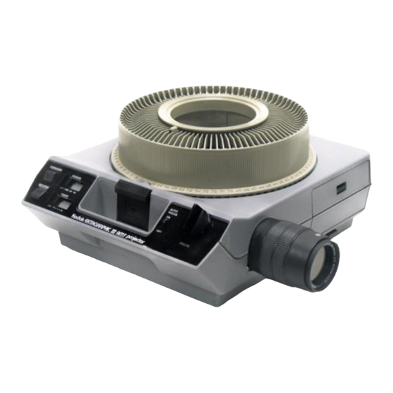
Kodak Ektagraphic III
Painted and Non-Painted PROJECTORS
Models A, KKA, JA, ATS, AM, AMT, JAMT, B, BR, E,
E-PLUS SLIDE, J-E PLUS, and KKE PLUS
Kodak Home Page
on Internet
Intranet
Table of Contents
A100_0001HA
© Eastman Kodak Company, 1999
Advertisement
Table of Contents

Related Manuals for Kodak KODAK EKTAGRAPHIC III AM


Summary of Contents for Kodak KODAK EKTAGRAPHIC III AM
- Page 1 Kodak Ektagraphic III Painted and Non-Painted PROJECTORS Models A, KKA, JA, ATS, AM, AMT, JAMT, B, BR, E, E-PLUS SLIDE, J-E PLUS, and KKE PLUS Kodak Home Page on Internet Intranet Table of Contents A100_0001HA © Eastman Kodak Company, 1999...
-
Page 2: Table Of Contents
Eastman Kodak Company reserves the right to change this information without notice, and makes no warranty, express or implied, with respect to this information. Kodak shall not be liable for any loss or damage, including consequential or special damages, resulting from any use of this information, even if loss or damage is caused by Kodak’s negligence or other fault. - Page 3 Adjusting the SLIDE LIFT LEVER POWER Adjusting the ZERO POSITION Adjusting the Focus Light Path - Auto Focus Models Adjusting the Adjusting the PHOTOCELL Adjusting the CLAMP PAD ASSEMBLY Adjusting the DARK SHUTTER Lubrication ............. Tools .
-
Page 4: Replacements And Installations
SERVICE MANUAL Section 1: Replacements and Installations Replacing the LOWER HOUSING ASSEMBLY Warning Dangerous Voltage [1] Disconnect the main power. [2] Remove the PROJECTION LENS. [3] Remove the LAMP MODULE ASSEMBLY. [4] Remove the 6 Torx SCREWS (for N.P. models) (or 6 Phillips SCREWS for Painted Models) from the LOWER HOUSING ASSEMBLY. -
Page 5: Replacing The Fan Shaft Assembly
Replacing the FAN SHAFT ASSEMBLY A100_0013HCA A100_0013HA Warning Dangerous Voltage [1] Disconnect the main power. [2] Do the replacement procedure for the LOWER HOUSING ASSEMBLY. [3] Cut the 3 WIRE TIES: • 1 on BLOWER COVER wires • 2 on SMALL CIRCUIT BOARD between the MOTOR and MECHANISM ASSEMBLY [4] Disconnect the 2 wires from the CYCLE SOLENOID on the SMALL CIRCUIT BOARD. - Page 6 [18] Remove the FAN BELT. [19] N.P. only: Remove the 3 Torx SCREWS from the FAN SHAFT ASSEMBLY. [20] Lift and remove the FAN SHAFT ASSEMBLY. SCREW (3) BLOWER ASSEMBLY SCREW FAN PLATE Painted PROJECTOR FAN CAP E-RING SPRING WASHER WASHER CORK WASHER...
-
Page 7: Installing The Fan Shaft Assembly
Installing the FAN SHAFT ASSEMBLY Important When installing the FAN and MECHANISM BELTS, install the MECHANISM BELT on the small MOTOR PULLEY, and the FAN BELT on the large MOTOR PULLEY. [1] Do the removal procedure for the FAN BELT and SHAFT in reverse order. Replacing the MOTOR SCREW (3) MOTOR... -
Page 8: Installing The Motor
SERVICE MANUAL Installing the MOTOR Important When installing the FAN and MECHANISM BELTS, install the MECHANISM BELT on the small MOTOR PULLEY, and the FAN BELT on the large MOTOR PULLEY. [1] Do the replacement procedure for the MOTOR in reverse order. Replacing the WORM PULLEY and MECHANISM BELT SCREW A091_4017GCA... -
Page 9: Installing The Worm Pulley And Mechanism Belt
Installing the WORM PULLEY and MECHANISM BELT Important When installing the FAN and MECHANISM BELTS, install the MECHANISM BELT on the small MOTOR PULLEY, and the FAN BELT on the large MOTOR PULLEY. [1] Do the replacement procedure for the WORM PULLEY and MECHANISM BELT in reverse order. Replacing the THERMAL FUSE ASSEMBLY Warning Dangerous Voltage... -
Page 10: Installing The Thermal Fuse Assembly
SERVICE MANUAL Installing the THERMAL FUSE ASSEMBLY SCREW PRE-HEAT DUCT THERMAL FUSE A100_0015GCA POWER SWITCH A100_0015GA [1] Do the replacement procedure for the THERMAL FUSE ASSEMBLY in reverse order. 30APR96 – SM4530-1... -
Page 11: Replacing The Lamp Module Receptacle
Replacing the LAMP MODULE RECEPTACLE SCREW (2) LOWER LIGHT BAFFLE A100_0016HCA A100_0016HA Warning Dangerous Voltage [1] Disconnect the main power. [2] Do the replacement procedure for the LOWER HOUSING ASSEMBLY. [3] Cut and remove the necessary WIRE TIES. [4] Remove the 2 Torx SCREWS on the left side of the LOWER LIGHT BAFFLE ASSEMBLY. [5] Loosen the Torx SCREW on the right side of the LOWER LIGHT BAFFLE ASSEMBLY approximately 1/2 way. -
Page 12: Replacing The Cycle Solenoid Assembly
SERVICE MANUAL Replacing the CYCLE SOLENOID ASSEMBLY CYCLE SOLENOID CYCLE SOLENOID PLUNGER Installing the CYCLE SOLENOID ASSEMBLY Important Do the adjustment for the CYCLE SOLENOID ASSEMBLY. See the Adjustments section. [1] Do the replacement procedure for the CYCLE SOLENOID ASSEMBLY in reverse order. Warning Dangerous Voltage [1] Disconnect the main power. -
Page 13: Replacing The Mechanism Assembly
Replacing the MECHANISM ASSEMBLY SCREW (3) LENS MOUNT SCREW FOCUS KNOB AUTO FOCUS DEFEAT SWITCH A091_4022CCA (not shown) A091_4022CA SM4530-1 – 30APR96 SCREW Warning DARK SHUTTER Dangerous Voltage SWITCH [1] Disconnect the main power. [2] Do the replacement procedure for the LOWER HOUSING ASSEMBLY. -
Page 14: Installing The Mechanism Assembly
SERVICE MANUAL Installing the MECHANISM ASSEMBLY Important To insert the SELECT BUTTON into the hole in the SELECT LEVER when installing the MECHANISM ASSEMBLY, hold the SELECT BUTTON completely down. [1] Do the removal procedure for the MECHANISM ASSEMBLY in reverse order. Replacing the AUTO-FOCUS BRACKET ASSEMBLY SCREW AUTO... -
Page 15: Replacing The Cam Stack Assembly And Cycle Lever Assembly
Replacing the CAM STACK ASSEMBLY and CYCLE LEVER ASSEMBLY STYLE 1 RETARD SPRING E-RING BEARING STYLE 2 RETARD SPRING Warning Dangerous Voltage [1] Disconnect the main power. [2] Do the replacement procedure for the MECHANISM ASSEMBLY. [3] Remove the INDEXER LEVER ASSEMBLY from the TOP PLATE of the MECHANISM ASSEMBLY. [4] Remove the Torx SCREW (on N.P. - Page 16 SERVICE MANUAL [12] Remove the LIGHT BAFFLE. SELECT LEVER SELECT LEVER SPRING CAM STACK ASSEMBLY [13] Remove the NUT from the LIFT LEVER SHAFT. [14] Remove the LIFT LEVER and SHAFT. [15] Remove the 2 E-RINGS from the 2 CAM SHAFT BEARINGS. [16] Remove the 2 CAM SHAFT BEARINGS.
-
Page 17: Installing The Cam Stack Assembly And Cycle Lever Assembly
HALF-CYCLE LEVER HALF-CYCLE LEVER SPRING CYCLE LEVER PLUNGER SPRING PLUNGER CYCLE SOLENOID SCREW (2) INDEX LEVER and SPRING (not shown) Installing the CAM STACK ASSEMBLY and CYCLE LEVER ASSEMBLY Caution Keep both the CYCLE LEVER ASSEMBLY and the HALF CYCLE LEVER together and observe the orientation of both LEVERS. -
Page 18: Replacing The Lamp Socket Terminal Assembly, N.p
LAMP MODULE next to the LAMP MODULE DOOR. [6] Remove the LAMP DOOR PLATE ASSEMBLY. Caution PROJECTOR Remove the CONDENSER LENS and HEAT LAMP ABSORBING GLASS and set the parts on a clean cloth. Do not set on a cold surface; this will cause LAMP damage to the parts. -
Page 19: Replacing The Lamp Socket Terminal Assembly, Painted Models
• PROJECTION LAMP for the LAMP MODULE from the LAMP MODULE • SCREW and lift the CONDENSER LENS HOLDER up • CONDENSER LENS and HEAT GLASS • RETAINING RING • SPRING WASHER • SOCKET PIN SM4530-1 – 30APR96 PROJECTOR LAMP LAMP EJECTOR Replacements and Installations CONDENSER 6 TABS... -
Page 20: Installing The Lamp Socket Terminal Assembly, Painted Models
SERVICE MANUAL Caution The TABS could break. [3] Bend the 3 TABS of the LAMP BRACKET ASSEMBLY. [4] Lift the top of the LAMP BRACKET ASSEMBLY up. [5] Rotate and push the LAMP TERMINAL ASSEMBLY until it releases. [6] Remove the LAMP TERMINAL ASSEMBLY. Installing the LAMP SOCKET TERMINAL ASSEMBLY, Painted Models [1] Do the replacement procedure for the LAMP SOCKET TERMINAL ASSEMBLY in reverse order and check the following during installation:... -
Page 21: Replacing The Lens Mount Assembly - Non Auto Focus Model
Replacing the LENS MOUNT ASSEMBLY - Non Auto Focus Model SCREW (3) LENS MOUNT ASSEMBLY A100_0019GCA A100_0019GA Installing the LENS MOUNT ASSEMBLY - Non Auto Focus Model [1] Do the replacement procedure for the LENS MOUNT ASSEMBLY in reverse order. SM4530-1 –... -
Page 22: Replacing The Auto-Focus Switch Assembly
SERVICE MANUAL Replacing the AUTO-FOCUS SWITCH ASSEMBLY AUTO FOCUS MOTOR BRACKET LOCKING AUTO FOCUS SWITCH LEVER AUTO FOCUS SWITCH ASSEMBLY Installing the AUTO-FOCUS SWITCH ASSEMBLY Important Align the 2 TABS on the AUTO-FOCUS SWITCH with the FOCUS MOTOR BRACKET, checking that the end of the AUTO-FOCUS LEVER engages with the CYCLE SOLENOID PLUNGER. -
Page 23: Replacing The Focus Shaft Assembly - Auto Focus Models
Replacing the FOCUS SHAFT ASSEMBLY - Auto Focus Models RACK LEVER (not shown) FOCUS SHAFT FOCUS MOTOR BRACKET SPACER E-RING PHOTOCELL AUTO-FOCUS BRACKET SWITCH SPRING ASSEMBLY Warning Dangerous Voltage [1] Disconnect the main power. [2] Do the replacement procedure for the LOWER HOUSING ASSEMBLY. [3] Remove the FOCUS KNOB. -
Page 24: Installing The Focus Shaft Assembly
SERVICE MANUAL [17] Remove the FOCUS MOTOR BRACKET ASSEMBLY. [18] Push the RACK LEVER away from the FOCUS SHAFT ASSEMBLY. [19] Remove the FOCUS SHAFT ASSEMBLY. Installing the FOCUS SHAFT ASSEMBLY Important Do the adjustments for the PHOTOCELL NULL and AUTO-FOCUS CLAMP after installation. See the Adjustments section. -
Page 25: Installing The Focus Shaft Assembly
Replacements and Installations [12] Remove the FOCUS MOTOR BRACKET ASSEMBLY. [13] Remove the FOCUS SHAFT ASSEMBLY. Installing the FOCUS SHAFT ASSEMBLY [1] Do the replacement procedure for the FOCUS SHAFT ASSEMBLY in reverse order. SM4530-1 – 30APR96... -
Page 26: Adjustments
[2] Do the removal for the LOWER HOUSING ASSEMBLY. [3] Bend the CYCLE LEVER up or down. Use T-BAR TL-3003. [4] Energize the projector. [5] Press the “FORWARD” BUTTON to check for correct operation. [6] Press the “REVERSE” BUTTON to check for correct operation. -
Page 27: Adjusting The Indexer Lever Assembly
Adjustment Specification This adjustment adjusts the strobe and timing of the INDEXER LEVER. Use TL-3000. The gate edge of the black plastic of the INDEXER LEVER should be between the 2 holes at position 2. Adjusting the INDEXER LEVER ASSEMBLY MECHANISM ASSEMBLY MECHANISM... -
Page 28: Adjusting The Slide Lift Lever Manual
SERVICE MANUAL Adjusting the SLIDE LIFT LEVER MANUAL SLIDE LIFT LEVER GUAGE TL-3001 Warning Dangerous Voltage [1] Disconnect the main power. Important The older style MECHANISM SLIDE LIFT LEVER has an ECCENTRIC on it to do this adjustment. [2] Do the removal for the MECHANISM ASSEMBLY. [3] Place the MECHANISM ASSEMBLY on the MECHANISM RUNNING FIXTURE TL-3000. -
Page 29: Adjusting The Slide Lift Lever Power
Adjusting the SLIDE LIFT LEVER POWER SLIDE LIFT LEVER GUAGE TL-3001 Warning Dangerous Voltage [1] Disconnect the main power. Important The older style MECHANISM SLIDE LIFT LEVER has an ECCENTRIC on it to do this adjustment. [2] Do the removal for the MECHANISM ASSEMBLY. [3] Place the MECHANISM ASSEMBLY on the MECHANISM RUNNING FIXTURE TL-3000. -
Page 30: Adjusting The Zero Position Switch
Important It is necessary to make a 5/16 in. WRENCH to do this adjustment. See the Tools section. [1] Energize the projector. [2] Connect the DIGITAL VOLT METER (DVM) between PINS 1 and 3 (ZERO POSITION SWITCH) of the SPECIAL APPLICATIONS PLUG. -
Page 31: Adjusting The Focus Light Path - Auto Focus Models
[4] Install the FAN COVER TOOL over the FAN area and the LAMP MODULE. [5] Energize the projector. [6] Set the projector to the LOW LAMP position. [7] Install the AUTO-FOCUS TARGET SLIDE TL-3002 until it is fully seated in the GATE MECHANISM. -
Page 32: Adjusting The Null
[3] Install the FAN COVER TOOL over the FAN area and the LAMP MODULE. See the Tools section. [4] Energize the projector. [5] Set the projector to the LO-LAMP position. [6] Install and hold the AUTO FOCUS TARGET SLIDE TL-3002 until it is fully seated in the GATE MECHANISM. -
Page 33: Adjusting The Photocell
[3] Install the FAN COVER TOOL over the FAN area and the LAMP MODULE. See the Tools section. [4] Energize the projector. [5] Set the projector to the LO-LAMP position. [6] Install and hold the AUTO FOCUS TARGET SLIDE TL-3002 until it is fully seated in the GATE MECHANISM. - Page 34 [15] Install and hold the AUTO FOCUS TARGET SLIDE TL-3002 until it is fully seated in the GATE MECHANISM. [16] Set the projector to the LO-LAMP position. [17] Observe the image of the focus light path on the bottom of the FAN CAP; the light path should be in the center of the hole in the FAN CAP.
-
Page 35: Adjusting The Clamp Pad Assembly
Adjustment Specification Use TL-1744 to check that the CLAMP PAD ASSEMBLY moves forward and backward. Adjusting the CLAMP PAD ASSEMBLY SCREW CLAMP PAD ASSEMBLY Adjustment Specification The PRESSURE PAD should be aligned with the DARK SHUTTER. SM4530-1 – 30APR96 Warning Dangerous Voltage [1] Disconnect the main power. -
Page 36: Adjusting The Dark Shutter
SERVICE MANUAL Adjusting the DARK SHUTTER DARK SHUTTER [1] Do the removal for the LOWER HOUSING. [2] Insert a thin SLIDE into the GATE MECHANISM; the DARK SHUTTER should open. [3] Check the the PRESSURE PAD is correctly aligned with the the DARK SHUTTER. [4] Bend the PRESSURE PAD to adjust the alignment. -
Page 37: Lubrication
Section 3: Lubrication [1] Apply lubricant SUPER LUBE TL-4276 to the following parts and areas of the projector; see the illustrations: • FAN • INDEXER LEVER and TOP PLATE • WORM PULLEY ASSEMBLY • CAM STACK ASSEMBLY • CYCLE LEVERS •... - Page 38 SERVICE MANUAL A091_0023HA 30APR96 – SM4530-1...
- Page 39 Lubrication A091_0022DA SM4530-1 – 30APR96...
-
Page 40: Tools
TL-3002 TL-3003 TL-3005 TL-3255 TL-4276 The LOWER HOUSING ASSEMBLY is a part of the cooling function. To operate the projector with the LOWER HOUSING removed, make a FAN COVER TOOL. Description AUTO-FOCUS GAUGE FOCUS TEST (flat field) MECHANISM RUNNING FIXTURE (optional) -
Page 41: Specifications
• 21 - 27 C (70 - 80 F), 20 - 60% humidity optimum Fan speed is 2780 or 3000 RPMs, 1360 BTUs per hour to cool projector Complies with storage test specifications (TS 172) Complies with climactic test specifications (TS 218) •... - Page 42 3 times the focus and reverse specifications. The projector can operate for 2000 hours or 2,000,000 cycles. The projector has a MTBF (mean time between failures) of 7500 operation hours. Preventive maintenance by a qualified service person is recommended every 1500 hours of operation, or after 1 year.
-
Page 43: Diagnostics
Section 6: Diagnostics MAIN MOTOR Voltages MOTOR MAIN MOTOR PIN Colors MAIN MOTOR PIN Voltages 10-11 11-12 10-12 SM4530-1 – 30APR96 brown violet yellow blue not used Voltage 25.5 V ac 14.5 V ac 14.5 V ac 29 V ac Diagnostics 84.2 V brown... -
Page 44: 9-Pin Special Application Plug
SERVICE MANUAL 9-PIN SPECIAL APPLICATION PLUG SPECIAL APPLICATIONS PLUG A100_0022ACA A100_0022AA 9-PIN SPECIAL APPLICATION PLUG PINS 1 and 3 ZERO POSITION SWITCH 4 and 5 SHUTTER SWITCH 7 and 8 LOWER VOLTAGE SUPPLY, 2.5 V AC, 500 mA, 1/2 Amp maximum 6 and 8 FORWARD TRAY CYCLE 2 and 8... -
Page 45: 5-Pin Remote Cord Plug Voltages
5-PIN REMOTE CORD PLUG Voltages A100_0001BC_ 5-PIN REMOTE PLUG Voltages white yellow brown black SM4530-1 – 30APR96 BLACK WHITE YELLOW YELLOW KODAK EC-3 REMOTE CONTROL Description Reverse Forward Common RACK SOLENOID Focus - REMOTE Diagnostics FOCUS... -
Page 46: Small Component Board Assembly 256809 Voltages
FOCUS FOCUS RACK USE REMOTE FOCUS FOCUS W K R A V V O B Y SLIDE PROJECTOR BOARD Component RED +, BLACK - + to - - G to + A - G to + K + to -... -
Page 47: Voltage Specifications - General Parts
Voltage Specifications - General Parts Part FOCUS MOTOR None CYCLE SOLENOID Press the REVERSE BUTTON. RACK SOLENOID None LAMP RECEPTACLE None DROPPING RESISTOR Move to the LO LAMP position. Power, Illumination, and Cooling Malfunctions Malfunction The MOTOR does not operate. The FAN does not operate, MOTOR operates. -
Page 48: Slide Transport Malfunctions
CONTROL. Forward does not operate, reverse operates, voltages are correct. Reverse does not operate, forward operates, voltages are correct. Projector does not complete a cycle; FAN operates. Projector has continual cycle. Check 1. Check that the secondary voltage on the MAIN MOTOR is correct. - Page 49 Malfunction The projector does not change cycles when using a DISSOLVE CONTROL; the REMOTE CONTROL and CONTROL PANEl BUTTONS operate correctly. SLIDE TRAY does not advance smoothly. SLIDE TRAY advances when “REVERSE” is pressed. SLIDE TRAY does not rotate freely when the SELECT BUTTON is pressed down.
- Page 50 2. Move the TIMER BUTTON forward and backward; use a DVM to check for changes in W. 3. Energize the projector and move the TIMER to “S”. • Check the voltages on CR3, Q3, and Q4, see the voltage table.
-
Page 51: Focus Malfunctions
Focus Malfunctions Malfunction No manual focus No remote focus (Non Auto Focus models) No remote focus, RACK SOLENOID ASSEMBLY operates (Auto Focus Models) SM4530-1 – 30APR96 Check 1. Check the FOCUS SHAFT SPRING for the correct tension. 2. Check the LENS SUPPORT SPRING for correct tension. - Page 52 SERVICE MANUAL Malfunction No auto-focus Slow auto-focus movement Check 1. Check that the AUTO-FOCUS DEFEAT SWITCH is in the “ON” position. 2. Check that the MAIN PROJECTION LAMP operates correctly. 3. Insert the TARGET SLIDE TL-3002 in the GATE MECHANISM. •...
- Page 53 Malfunction AUTO FOCUS MOTOR operates continually AUTO FOCUS MOTOR operates continually in forward only or reverse only and does not operate (stops) in the null position. AUTO FOCUS adjusts after REMOTE use SM4530-1 – 30APR96 Check 1. Install the TARGET SLIDE TL-3002 in the GATE MECHANISM.
- Page 54 Kodak, Ektagrphic, and Wratten are tradmarks. Printed in U.S.A. • sm4530_1.fm EASTMAN KODAK COMPANY Rochester, NY 14650...