Toshiba B-EX4 SERIES Maintenance Manual
Hide thumbs
Also See for B-EX4 SERIES:
- Maintenance manual (294 pages) ,
- Product description (55 pages) ,
- Quick installation manual (8 pages)

Related Manuals for Toshiba B-EX4 SERIES


Summary of Contents for Toshiba B-EX4 SERIES
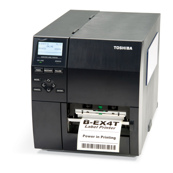
- Page 1 TOSHIBA Thermal Printer B-EX4 SERIES Maintenance Manual Document No. EO18-33027 Original Mar, 2011 (Revised (PRELIMINARY VERSION) PRINTED IN JAPAN...
-
Page 2: Table Of Contents
EO18-33027 TABLE OF CONTENTS Page UNPACKING-------------------------------------------------------------------------------------------------------- 1- 1 PROCEDURES ---------------------------------------------------------------------------------------------------1- 1 CHECKS ------------------------------------------------------------------------------------------------------------1- 3 PRINTER INSTALLATION-------------------------------------------------------------------------------------- 1- 3 NOTE FOR OPTIONAL EQUIPMENT INSTALLATION /MAJOR UNIT REPLACEMENT/MAINTENANCE---------------------------------------------------- 3- 1 OPENING/CLOSING THE TOP COVER-------------------------------------------------------------------3- 3 REMOVING THE SIDE PANEL (L) --------------------------------------------------------------------------3- 3 OPENING/CLOSING THE PRINTER BLOCK ------------------------------------------------------------3- 3 REMOVING THE OPERATION PANEL --------------------------------------------------------------------3- 5 INSTALLATION PROCEDURE FOR OPTIONAL EQUIPMENT ------------------------------------- 4- 1... - Page 3 EO18-33027 SYSTEM MODE---------------------------------------------------------------------------------------------------- 5- 1 OPERATION PANEL --------------------------------------------------------------------------------------------5- 1 OVERVIEW --------------------------------------------------------------------------------------------------------5- 2 SELF-DIAGNOSTIC TEST-------------------------------------------------------------------------------------5- 3 5.3.1 Counter, Parameter / MAINTENACE COUNT ------------------------------------------------------ 5- 3 5.3.2 Auto Diagnostic / AUTO DIAGNOTICS ------------------------------------------------------------- 5-16 5.3.3 Print Head Element Check ------------------------------------------------------------------------------ 5-23 PARAMETER SETTING ---------------------------------------------------------------------------------------5-24 5.4.1 Printer setting / PRINTER SET ------------------------------------------------------------------------ 5-24 5.4.1.1 Media loading / MEDIA LOAD------------------------------------------------------------------- 5-24...
- Page 4 EO18-33027 Fine adjustment value setting/ ADJUST SET ------------------------------------------------------------5-37 5.5.1 Feed / FEED ADJ.----------------------------------------------------------------------------------------- 5-38 5.5.2 Cut position / CUT ADJ ---------------------------------------------------------------------------------- 5-38 5.5.3 Back feed / BACK ADJ----------------------------------------------------------------------------------- 5-43 5.5.4 X direction position / X ADJUST ----------------------------------------------------------------------- 5-44 5.5.5 Density fine tune (Thermal transfer) / TONE ADJ.(TRANS.) ---------------------------------- 5-44 5.5.6 Density fine tune (Direct thermal transfer) / TONE ADJ.(DIRECT) --------------------------- 5-44 5.5.7...
- Page 5 EO18-33027 ON LINE MODE-----------------------------------------------------------------------------------------------------6-1 THRESHOLD SETTING -------------------------------------------------------------------------------------------- 6-8 ONLINE MODE LCD DISPLAY --------------------------------------------------------------------------------- 6-11 HELP DISPLAY ----------------------------------------------------------------------------------------------------- 6-14 PERIODIC MAINTENANCE PROCEDURE ---------------------------------------------------------------- 7- 1 TROUBLESHOOTING -------------------------------------------------------------------------------------------- 8 1 (TBD) 10. MAJOR UNIT REPLACEMENT (T.B.D)----------------------------------------------------------------------10- 10.1 POWER SUPPLY UNIT----------------------------------------------------------------------------------------- 10- 10.2 MAIN PC BOARD ------------------------------------------------------------------------------------------------ 10- 10.3 PANEL PC BOARD AND LCD UNIT ------------------------------------------------------------------------ 10- 10.3.1 LCD ------------------------------------------------------------------------------------------------------------- 10- 10.3.2 Panel PC Board---------------------------------------------------------------------------------------------- 10-...
- Page 6 EO18-33027 CAUTION! 1. This manual may not be copied in whole or in part without prior written permission of TOSHIBA TEC. 2. The contents of this manual may be changed without notification. Copyright © 2011 by TOSHIBA TEC CORPORATION All Rights Reserved...
-
Page 7: Unpacking
1. UNPACKING EO18-33027 1.1 PROCEDURE 1. UNPACKING 1.1 PROCEDURE Open the carton. Unpack the accessories and the front pad from the carton. Accessories Carton Front Pad Unpack the pads and the printer from the carton. Remove the four pieces of tape and the rear pad from the printer. Tape Tape 1- 1... - Page 8 1. UNPACKING EO18-33027 1.1 PROCEDURE Open the top cover and remove the five pieces of tape. And then, open the ribbon shaft holder plate to remove the ribbon shaft pad from the printer. Top Cover Tape Ribbon Shaft Pad Tape OPEN Ribbon Shaft Holder Plate 1- 2...
-
Page 9: Checks
1. UNPACKING EO18-33027 1.2 CHECKS 1.2 CHECKS Check for damage or scratches on the printer. Confirm that none of the accessories are missing. The parts below are provided as accessories. CD-ROM (1 pc.) <Contents> • Bar code printer application (BarTender Ultra Lite) •... -
Page 10: Note For Optional Equipment Installation /Major Unit Replacement/Maintenance
3. NOTE FOR OPTIONAL EQUIPMENT INSTALLATION/MAJOR UNIT REPLACEMENT EO18-33027 /MAINTENANCE 3. NOTE FOR OPTIONAL EQUIPMENT INSTALLATION/MAJOR UNIT REPLACEMENT/MAINTENANCE 3. NOTE FOR OPTIONAL EQUIPMENT INSTALLATION /MAJOR UNIT REPLACEMENT/MAINTENANCE WARNING! 1. Turn the power off and disconnect the power cord before replacing the main parts. Power Switch Power Cord 2. - Page 11 3. NOTE FOR OPTIONAL EQUIPMENT INSTALLATION/MAJOR UNIT REPLACEMENT EO18-33027 /MAINTENANCE 3. NOTE FOR OPTIONAL EQUIPMENT INSTALLATION/MAJOR UNIT REPLACEMENT/MAINTENANCE 2. Do not remove the screws below. Doing so will require the printer block position adjustment with the jig. Printer Block Screw 3.
-
Page 12: Opening/Closing The Top Cover
3. NOTE FOR OPTIONAL EQUIPMENT INSTALLATION/MAJOR UNIT REPLACEMENT EO18-33027 /MAINTENANCE 3.1 OPENING/CLOSING THE TOP COVER 3.1 OPENING/CLOSING THE TOP COVER When opening the top cover, fully open the top cover to the open position. When closing, softly close it to the close position. O p e n p o s i t i o n C l o s e p o s i t i o n 3.2 REMOVING THE SIDE PANEL (L) - Page 13 3. NOTE FOR OPTIONAL EQUIPMENT INSTALLATION/MAJOR UNIT REPLACEMENT EO18-33027 /MAINTENANCE 3.3 OPENING/CLOSING THE PRINTER BLOCK Raise the print head block until it stops. Print Head Block NOTE: DO NOT excessively push down the print head block to close it. Dosing so may cause a failure of the print head block or damage to the print head.
-
Page 14: Removing The Operation Panel
3. NOTE FOR OPTIONAL EQUIPMENT INSTALLATION/MAJOR UNIT REPLACEMENT EO18-33027 /MAINTENANCE 3.4 REMOVING THE OPERATION PANEL 3.4 REMOVING THE OPERATION PANEL Open the top cover. (Refer to section 3.1.) Remove the side panel (L) from the printer. (Refer to section 3.2.) Fully open the top cover, otherwise the operation panel ass’y is stuck on the tab and cannot be removed from the printer. - Page 15 3. NOTE FOR OPTIONAL EQUIPMENT INSTALLATION/MAJOR UNIT REPLACEMENT EO18-33027 /MAINTENANCE 3.4 REMOVING THE OPERATION PANEL Disconnect the operation panel harness from the operation panel ass’y. Operation Panel Ass’y Operation Panel Harness 3- 6...
-
Page 16: Installation Procedure For Optional Equipment
4. INSTALLATION PROCEDURE FOR OPTIONAL EQUIPMENT EO18-33027 4. INSTALLATION PROCEDURE FOR OPTIONAL EQUIPMENT 4. INSTALLATION PROCEDURE FOR OPTIONAL EQUIPMENT WARNING! 1. Make sure to unplug the power cord before installing the optional equipment. 2. Be careful not to pinch your fingers or hands with the covers. CAUTION! When replacing parts or performing maintenance on the printer, be careful not to damage the print head with a hard object like a watch or a ring. - Page 17 4. INSTALLATION PROCEDURE FOR OPTIONAL EQUIPMENT EO18-33027 4.1DISC CUTTER (B-EX204-QM-R) 4.1 DISC CUTTER (B-EX204-QM-R) WARNING! Be careful not to injure your fingers when installing the cutter unit. All the following parts are supplied with the kit. Make sure you have all items shown below. Description Q’ty/Unit Description...
- Page 18 4. INSTALLATION PROCEDURE FOR OPTIONAL EQUIPMENT EO18-33027 4.1DISC CUTTER (B-EX204-QM-R) 4) Put the cutter in front of the printer. Connect one side of the cutter harness to CN15 on the Main PC Board. And connect another side to the disc cutter PC Board. Main PC Board CN15 CN15...
-
Page 19: Rotary Cutter (B-Ex204-R-Qm-R)
4. INSTALLATION PROCEDURE FOR OPTIONAL EQUIPMENT EO18-33027 4.2 ROTARY CUTTER (B-EX204-R-QM-R) 4.2 ROTARY CUTTER (B-EX204-R-QM-R) WARNING! Be careful not to injure your fingers when installing the cutter unit. All the following parts are supplied with the kit. Make sure you have all items shown below. Description Q’ty/Unit Description... - Page 20 4. INSTALLATION PROCEDURE FOR OPTIONAL EQUIPMENT EO18-33027 4.2 ROTARY CUTTER (B-EX204-R-QM-R) Rotary Cutter Guide Plate C Rotary Cutter Frame B (P/No.: 7FM01068000) Rotary Cutter Guide Plate B Rotary Cutter Frame A (P/No.: 7FM0167000) 4) Assemble the Rotary Cutter Frame A and Rotary Cutter Frame B with an SMW-4x8 screw removed in step 2).
- Page 21 4. INSTALLATION PROCEDURE FOR OPTIONAL EQUIPMENT EO18-33027 4.2 ROTARY CUTTER (B-EX204-R-QM-R) NOTE: When attaching the B-8204-QM cutter module, replace the original cutter paper guide C with the enclosed B-SX cutter paper guide C using the following procedure. CAUTION! Do not hold the cutter paper guides when attaching the Cutter Unit to the printer. Doing so may deform the cutter paper guides, causing a paper jam.
- Page 22 4. INSTALLATION PROCEDURE FOR OPTIONAL EQUIPMENT EO18-33027 4.2 ROTARY CUTTER (B-EX204-R-QM-R) 1) Turn the power off and disconnect the power cord. 2) Open the top cover, and push up the hooker and take out the front cover bottom. Front Plate Hooker 3) Remove the three M3x6 screws from the side panel (L).
- Page 23 4. INSTALLATION PROCEDURE FOR OPTIONAL EQUIPMENT EO18-33027 4.2 ROTARY CUTTER (B-EX204-R-QM-R) 5) Connect the 9-pin connector of the harness ass’y to CN7 on the cutter driver unit, respectively. Harness Ass’y CN7 (9 pins) 6) Fit the bush to the harness ass’y in the orientation as shown below. Harness Ass’y Insert the harness ass’y into the hole in the main frame.
- Page 24 4. INSTALLATION PROCEDURE FOR OPTIONAL EQUIPMENT EO18-33027 4.2 ROTARY CUTTER (B-EX204-R-QM-R) Fix the harness ass’y with the clamp. Connect the 9-pin connector of the harness ass’y to CN15, and 2-pin connector to CN18 on the Main PC board, respectively. Main PC Board CN15 (9 pins) Harness Ass’y 10) Turn the head lever counterclockwise to Free position.
- Page 25 4. INSTALLATION PROCEDURE FOR OPTIONAL EQUIPMENT EO18-33027 4.2 ROTARY CUTTER (B-EX204-R-QM-R) 13) Connect the four harnesses of the cutter unit to CN8, CN10, CN11 and CN12 on the cutter drive unit. Print Head Block Cutter Drive Unit CN12 CN10 Cutter Unit CN11 14) Fit the two tabs of the cutter drive unit into the notches, and then fix the cutter unit with the three SM-4x8 screws.
- Page 26 4. INSTALLATION PROCEDURE FOR OPTIONAL EQUIPMENT EO18-33027 4.2 ROTARY CUTTER (B-EX204-R-QM-R) 15) Attach the cutter cover to the cutter unit with the two screws so that the tab of the cutter cover turns on the cutter cover open switch. NOTES: 1. Be careful not to pinch the cutter harness by the cutter cover. 2.
-
Page 27: Peel Off Module (B-Ex904-H-Qm
4. INSTALLATION PROCEDURE FOR OPTIONAL EQUIPMENT EO18-33027 4.3 PEEL OFF MODULE (B-EX904-H-QM-R) 4.3 PEEL OFF MODULE (B-EX904-H-QM-R) This optional device is used for strip print, which cannot be used together with either B-EX204-QM-R or B-EX204-R-QM-R. When using a strip module together with an RFID module, be sure to install the RFID module prior to the strip module. - Page 28 4. INSTALLATION PROCEDURE FOR OPTIONAL EQUIPMENT EO18-33027 4.3 PEEL OFF MODULE (B-EX904-H-QM-R) 1) Turn the power off and disconnect the power cord. 2) Open the top cover, and push up the hooker and take out the front cover bottom. Front Plate Hooker 3) Remove the three M3x6 screws from the side panel (L).
- Page 29 4. INSTALLATION PROCEDURE FOR OPTIONAL EQUIPMENT EO18-33027 4.3 PEEL OFF MODULE (B-EX904-H-QM-R) Align the notch of the take-up holder with the screw hole of the rewinder ass’y, and attach them to the printer with the four M-3x6 screws and the M-3x6 screw. Attach the rewind full sensor (LED) to the base with the SM-3x6 screw.
- Page 30 4. INSTALLATION PROCEDURE FOR OPTIONAL EQUIPMENT EO18-33027 4.3 PEEL OFF MODULE (B-EX904-H-QM-R) Insert the longer harness of the rewind full sensor (Tr) into the hole in the printer frame. Fit the bush into the hole. Frame Bush Hole Longer Harness of the Rewind Full Sensor (Tr) Connect the longer harness of the rewind full sensor (Tr)and the rewinder harness to CN4 and CN15 on the Main PC board.
- Page 31 4. INSTALLATION PROCEDURE FOR OPTIONAL EQUIPMENT EO18-33027 4.3 PEEL OFF MODULE (B-EX904-H-QM-R) NOTES: 1. You should change the selection switch setting depending on the issue mode. Improper setting may affect the print quality. STANDARD/PEEL OFF (STRIP): Batch or strip mode REWINDER: Built-in rewinder mode For the cut mode, the selection switch can be set to...
- Page 32 4. INSTALLATION PROCEDURE FOR OPTIONAL EQUIPMENT EO18-33027 4.3 PEEL OFF MODULE (B-EX904-H-QM-R) 13) Raise the print head block until it stops. Print Head Block 14) Secure the strip sensor (LED) and strip sensor (Tr) to the printer with the M4x6 screws. 15) Connect the shorter harness of the strip sensor (Tr) to the strip sensor harness (for LED).
- Page 33 4. INSTALLATION PROCEDURE FOR OPTIONAL EQUIPMENT EO18-33027 4.3 PEEL OFF MODULE (B-EX904-H-QM-R) 16) Fix the connected strip sensor harness (for LED) to the base with the cable clamp. While passing the other strip sensor harness through the cut and the bush, reassemble the operation panel ass’y to the printer.
- Page 34 4. INSTALLATION PROCEDURE FOR OPTIONAL EQUIPMENT EO18-33027 4.3 STRIP MODULE (B-EX904-H-QM-R) 20) When using the printer in batch mode or strip mode, attach the front plate removed in step 2). 21) When using the printer in built-in rewinder mode, attach the rewinder guide plate to the front of the printer with the two SMW-4x8B screws.
-
Page 35: Ribbon Saving Module (B-Ex904-R-Qm
4. INSTALLATION PROCEDURE FOR OPTIONAL EQUIPMENT EO18-33027 4.4 RIBBON SAVING MODULE (B-EX904-R-QM-R) 4.4 RIBBON SAVING MODULE (B-EX904-R-QM-R) All the following parts are supplied with the kit. Make sure you have all items shown below. NOTE: The ribbon saving module is standard on the B-EX4T series. Solenoid (1 pc.) RSV PC Board (1 pc.) Solenoid Harness (1 pc.) - Page 36 4. INSTALLATION PROCEDURE FOR OPTIONAL EQUIPMENT EO18-33027 4.4 RIBBON SAVING MODULE (B-EX904-R-QM-R) Secure the RSV PC board to the printer with the locking supports. RSV PC Board Holes for securing the RSV PC Board Locking Support NOTE: Do not push the center of the RSV PC board when attaching it to the printer. Doing so may break the PC board.
- Page 37 4. INSTALLATION PROCEDURE FOR OPTIONAL EQUIPMENT EO18-33027 4.4 RIBBON SAVING MODULE (B-EX904-R-QM-R) Attach the cable clamp to the frame of the printer. Fix the solenoid cable with this cable clamp. Cable Clamp Solenoid Cable Solenoid Solenoid Harness NOTE: Be careful not to snag the solenoid harness when running it. Connect the solenoid harness to CN1 on the RSV PC board and CN11 on the Main PC board.
-
Page 38: Packing List
4. INSTALLATION PROCEDURE FOR OPTIONAL EQUIPMENT EO18-33027 4.5 USB INTERFACE BOARD (B-EX700-RTC-QM-R) 4.5 RTC/USB Host I/F Card (B-EX700-RTC-QM-R) This optional interface board is provided with the interface port, which allows for the installation of USB devices. WARNING! 1. Follow all manual instructions. Failure to do so could create safety hazards such as fire or electrocution. •... - Page 39 4. INSTALLATION PROCEDURE FOR OPTIONAL EQUIPMENT EO18-33027 4.5 USB INTERFACE BOARD (B-EX700-RTC-QM-R) Step 2. Remove the Blind Plate C from the back. Blind Plate C Step 3. Install the B-EX700-RTC-QM-R RTC/USB host I/F card in the printer. And fix the 2 M-3x6 screws from the back.
-
Page 40: Expansion I/O Interface Board (B-Ex700-Io-Qm
4. INSTALLATION PROCEDURE FOR OPTIONAL EQUIPMENT EO18-33027 4.6 EXPANSION I/O INTERFACE BOARD (B-EX700-IO-QM-R) 4.6 EXPANSION I/O INTERFACE BOARD (B-EX700-IO-QM-R) This optional interface board is provided with an expansion I/O interface. WARNING! 1. Follow all manual instructions. Failure to do so could create safety hazards such as fire or electrocution. •... - Page 41 4. INSTALLATION PROCEDURE FOR OPTIONAL EQUIPMENT EO18-33027 4.6 EXPANSION I/O INTERFACE BOARD (B-EX700-IO-QM-R) Installation Procedure Step 1. Remove the three M3x6 screws from the side panel (L). Move the side panel (L) to the back and push up it to remove. Side Panel (L) M3x6 Screw M3x6 Screw...
- Page 42 4. INSTALLATION PROCEDURE FOR OPTIONAL EQUIPMENT EO18-33027 4.6 EXPANSION I/O INTERFACE BOARD (B-EX700-IO-QM-R) Step 4. Connect the Expansion I/O Board harness to J3 on the Main PC Board. Connector J3 Expansion I/O Board harness Step 5. Reassemble the side panel (L) in the reverse order of removal. Step 6.
-
Page 43: Wireless Lan Board (B-Ex700-Wlan-Qm
4. INSTALLATION PROCEDURE FOR OPTIONAL EQUIPMENT EO18-33027 4.7 Wireless L AN BOARD (B-EX700WLAN-QM-R) 4. 7 WIRELESS LAN BOARD (B-EX700-WLAN-QM-R) This optional interface board is provided with an expansion I/O interface. WARNING! 1. Follow all manual instructions. Failure to do so could create safety hazards such as fire or electrocution. - Page 44 4. INSTALLATION PROCEDURE FOR OPTIONAL EQUIPMENT EO18-33027 4.7 Wireless L AN BOARD (B-EX700WLAN-QM-R) Installation Procedure Step 1. Remove the three M3x6 screws from the side panel (L). Move the side panel (L) to the back and push up it to remove. M3x6 Screw Side Panel (L) M3x6 Screw...
- Page 45 4. INSTALLATION PROCEDURE FOR OPTIONAL EQUIPMENT EO18-33027 4.7 Wireless L AN BOARD (B-EX700WLAN-QM-R) Step 4. Connect the Expansion I/O Board harness to J3 on the Main PC Board. Connector J3 Expansion I/O Board harness Step 5. Reassemble the side panel (L) in the reverse order of removal. Step 6.
- Page 46 4. INSTALLATION PROCEDURE FOR OPTIONAL EQUIPMENT EO18-33027 4.8 Parallel I/F card (B-EX700-CEN-QM-R) 4.8 PARALLEL INTERFACE card (B-EX700-CEN-QM-R) B-EX700-CEN-QM-R is an optional parallel interface card for the B-EX4T/EX6T-QM-R Series. WARNING! 1. Follow all manual instructions. Failure to do so could create safety hazards such as fire or electrocution. •...
- Page 47 4. INSTALLATION PROCEDURE FOR OPTIONAL EQUIPMENT EO18-33027 4.8 Parallel I/F card (B-EX700-CEN-QM-R) Installation Procedure Step 1. Remove the three M3x6 screws from the side panel (L). Move the side panel (L) to the back and push up it to remove. M3x6 Screw Side Panel (L) M3x6 Screw...
- Page 48 4. INSTALLATION PROCEDURE FOR OPTIONAL EQUIPMENT EO18-33027 4.8 Parallel I/F card (B-EX700-CEN-QM-R) Step 4. Connect the parallel interface harness to J2 on the Main PC Board. Connector J2 Parallel interface harness Step 5. Re-attach the Side Panel (L) to the printer. 4-33...
-
Page 49: System Mode
5. SYSTEM MODE EO18-33027 5.1 OPERATION PANEL 5. SYSTEM MODE The system mode can be entered by the following procedure from printer power off condition. • Press [FEED] key and [PAUSE] key at the same time • Press [MODE] Key In this mode, the printer self-test operation and parameter setting operation are performed. -
Page 50: Overview
5. SYSTEM MODE EO18-33027 5.2 OVERVIEW In System Mode, the keys function as described below. Compatible Key Function [MODE] Display top menu without saving setting. [CANCEL] [FEED] + [RESTART] Display upper menu without saving setting. [ENTER] [PAUSE] Display next menu. [UP] [FEED] Move cursor up. -
Page 51: Self-Diagnostic Test
5. SYSTEM MODE EO18-33027 5.3 SELF-DIAGNOSTIC TEST 5.3 SELF-DIAGNOSTIC TEST Outline of Self-Diagnostic Test In the Self-Diagnostic Test mode ,the printer checks and prints out the printer system information such as the sensor or interface, and the Maintenance Counter. Also it makes the print head broken element check. - Page 52 5. SYSTEM MODE EO18-33027 5.3 SELF-DIAGNOSTIC TEST • Menu operation procedure example English Procedure Press [FEED] key and [RESTART] key when turning on the printer. Display System Mode / SYSTEM MODE . Select <1>Diagnostics/<1>DIAG. and press [ENTER] Key. Display <1>Diagnostics/<1>DIAG. menu. Select Counter, Parameter/MAINTENANCE CONT and press [ENTER] Key.
- Page 53 5. SYSTEM MODE EO18-33027 5.3 SELF-DIAGNOSTIC TEST • COUNTER PARAMETE PRINT CONTENTS...
- Page 54 5. SYSTEM MODE EO18-33027 5.3 SELF-DIAGNOSTIC TEST Print condition: Label length 490mm Print method Setting by user Sensor type Speed 203dpi 6ips 305dpi 5ips Issuing number 1 piece Issuing mode Setting by user Other No mount winding motor << COUNTER >> Item Content Range...
- Page 55 5. SYSTEM MODE EO18-33027 5.3 SELF-DIAGNOSTIC TEST When the power is off, a drive time of 27 seconds or less is rounded down and backed up. 232C ERR RS-232C hardware error count Counts when a parity error or a framing error occurs. When data of several bytes is transmitted continuously, counting is performed per byte.
-
Page 56: Parameter Settings
5. SYSTEM MODE EO18-33027 5.3 SELF-DIAGNOSTIC TEST << PARAMETER SETTINGS >> Item Content Print value MEDIA LOAD Media loading Disable Feed detected gap/mark to stop position. Feed gap/mark between head and sensor to stop position. ECO+BFeed Perform back feed after completion of ECO. - Page 57 5. SYSTEM MODE EO18-33027 5.3 SELF-DIAGNOSTIC TEST Perform back feed after REFLECT+Bfe movement REFLECT. ON ALL+Bfeed Perform back feed fter movement of ON ALL. FONT Character code selection PC-850 PC-850 PC-852 PC-852 PC-857 PC-857 PC-8 PC-8 PC-851 PC-851 PC-855 PC-855 PC-1250 PC-1250 PC-1251...
- Page 58 5. SYSTEM MODE EO18-33027 5.3 SELF-DIAGNOSTIC TEST LBL/RBN END Label end/ribbon TYPE1 When a label end or process setting ribbon state detected, the printer stops even if it is printing. TYPE2 When a label end or ribbon state detected, the printer prints the current label as far as possible, then stops.
- Page 59 5. SYSTEM MODE EO18-33027 5.3 SELF-DIAGNOSTIC TEST BASIC TRACE Basic interpreter trace Trace is enabled. setting Trace is disabled. << PANEL >> Item Content Print value MESSAGE Language selection ENGLISH English messages GERMAN German FRENCH French DUTCH Dutch SPANISH Spanish JAPANESE Japanese ITALIAN...
- Page 60 5. SYSTEM MODE EO18-33027 5.3 SELF-DIAGNOSTIC TEST 2bit PARITY Parity selection NONE Non parity. Odd parity. EVEN Even parity. CONTROL Transmission control XON/XOFF XON/XOFF protocol method selection (No XON output when the power is on, no XOFF output when the power is off) READY/BUSY READY/BUSY (DTR) protocol...
- Page 61 5. SYSTEM MODE EO18-33027 5.3 SELF-DIAGNOSTIC TEST SOCKET PORT Socket communication Enable enable/disable Disable Socket communication port 0 65535 number DHCP DHCP setting DHCP function is enabled. DHCP function is disabled. DHCP CLIENT ID DHCP client ID setting (hex Max. 64 characters decimaldisplay) DHCP HOST NAME DHCP...
- Page 62 5. SYSTEM MODE EO18-33027 5.3 SELF-DIAGNOSTIC TEST 5.5M 5.5M POWER SAVE Wireless LAN: Power save Enable Disable WINS WINS enable/disable Enable Disable WINS IP ADDRESS WINS IP address ***.***.***.*** LPR enable/disable Enable Disable << RFID >> Item Content Print value MODULE RFID module type selection NONE...
- Page 63 5. SYSTEM MODE EO18-33027 5.3 SELF-DIAGNOSTIC TEST AGC THRESHOLD RFID AGC threshold setting WRITE AGC AGC threshold for data write RETRY MIN AGC AGC threshold lower limit for retry TAG CHECK RFID error tag detection Detection is disabled. ON(ID) RFID error detection for ID area data...
- Page 64 5. SYSTEM MODE EO18-33027 5.3 SELF-DIAGNOSTIC TEST 5.3.2 Auto Diagnostics/AUTO DIAGNOSTICS The printing procedure of “AUTO DIAGNOSTIC” of “DIAG.” is same as 5.3.1 Counter, Parameter/ MAINTENANCE COUNT . The manu layer from top menu of system mode to AUTO DIAGNOSTICS is below. MENU ITEM System Mode / SYSTEM MODE <1>Diagnostics / <1>DIAG.
- Page 65 5. SYSTEM MODE EO18-33027 5.3 SELF-DIAGNOSTIC TEST Print condition: Label length 100mm Print method Setting by user Sensor type Speed 203dpi Speed 305dpi Issuing number 1 piece Issuing mode Setting by user Other No mount winding motor NOTES: “ ” (degree) of “xx ” may not be printed correctly depend on code page selection. Main program file name of basic and system mode program file name is printed.
- Page 66 5. SYSTEM MODE EO18-33027 5.3 SELF-DIAGNOSTIC TEST EEPROM 256B 256B: The data of checking area can be read/write correctly. Alphanumeric character is capacity of EEPROM. NG: The data of checking area can not be read/write correctly. Memory for backup SDRAM 32MB Capacity of SDRAM Memory for system and drawing...
- Page 67 5. SYSTEM MODE EO18-33027 5.3 SELF-DIAGNOSTIC TEST SENSOR2 [H]20 C [A]22 C Open-air temperature sensor status 0 to 86 °C, --°C if it cannot be detected) Thermal head temperature sensor status (0 to 86 °C) [R]4.2V [T]2.5V [E]2.7V Reflective sensor status for detecting the ribbon end state (0.0 to 5.0 V) Transmissive sensor status (0.0 to 5.0 V) Reflective sensor status (0.0 to 5.0 V)
- Page 68 5. SYSTEM MODE EO18-33027 5.3 SELF-DIAGNOSTIC TEST Expansion I/O check contents EXP.I/O NG OK: Normal data NG: Abnormal data or the loop-back jig is not connected. Expansion I/O Connect the cable as illustrated below, then check the high output/high input, low output/low input. Internal serial I/F check contents EX.232C NG OK: Normal data...
- Page 69 5. SYSTEM MODE EO18-33027 5.3 SELF-DIAGNOSTIC TEST RFID module check contents RFID OK #00RV972 (EU0) R01 Module revision (U2 series only) Destination (U2 series only) RFID module version OK: Normal state NG: Erroneous state RFID module Module revisions and corresponding countries B-SX704-RFID-U2-US-R Revision Country...
- Page 70 5. SYSTEM MODE EO18-33027 5.3 SELF-DIAGNOSTIC TEST USB memory mounts check contents USB MEMORY NG OK: Mounted NG: Not mounted USB memory BASIC program check contents BASIC M NONE NONE: No program Version: Program exist BASIC main program BASIC S NONE NONE: No program Version: Program exist BASIC system program...
-
Page 71: Counter, Parameter / Maintenace Count
5. SYSTEM MODE EO18-33027 5.3 SELF-DIAGNOSTIC TEST 5.3.3 Head broken dot check/HEAD CHECK The printing procedure of “Head check” of “DIAG.” is same as 5.3.1 Counter, Parameter/ MAINTENANCE COUNT . The menu layer from top menu of system mode to HEAD CHECK is below. MENU ITEM System Mode / SYSTEM MODE <1>Diagnostics / <1>DIAG. -
Page 72: Parameter Setting
5. SYSTEM MODE EO18-33027 5.4 PARAMETER SETTING 5.4 PARAMETER SETTING Outline of Parameter Setting In the Parameter Setting mode, various kinds of parameters, such as communication, key, LCD, etc. can be set. This will allow the use of the printer to comply with your operating conditions. The Parameter Setting menu contains the following: MENU ITEM System Mode / SYSTEM MODE... -
Page 73: Setting For Forward Feed Standby / Forward Wait
5. SYSTEM MODE EO18-33027 5.4 PARAMETER SETTING 5.4.1.1 Media loading / MEDIA LOAD Disable / OFF Media loading function is disabled (Same as feed by machine’s key) Standard / STD When printer is tuned on, printer is resettled batch, or head is closed, printer detects gap/mark and feed the paper from sensor to thermal head which is home position. -
Page 74: Ribbon Save / Rbn Save
5. SYSTEM MODE EO18-33027 5.4 PARAMETER SETTING 5.4.1.6 Ribbon save / RBN SAVE Tag / TAG Enable ribbon save function (Head open/close lever: Tag position) Label / LABEL Enable ribbon save function (Head open/close lever: Label position) Disable / OFF Disable ribbon save function (*1) If this setting is enabled when ribbon module is not mounted, ribbon may be slack and printer may not print correctly. -
Page 75: Soft Control Setting / Software Set
5. SYSTEM MODE EO18-33027 5.4 PARAMETER SETTING 5.4.2 Soft control setting / SOFTWARE SET Menu list Soft control setting / SOFTWARE SET MENU ITEM System Mode / SYSTEM MODE <2>Parameter setting / <2>PARAMETER SET Soft control setting / SOFTWARE SET Character code / FONT CODE Font “0”... -
Page 76: Manual Selection / Manual
5. SYSTEM MODE EO18-33027 5.4 PARAMETER SETTING 5.4.2.1 Character code / FONT CODE PC-850 PC-852 PC-857 PC-8 PC-851 PC-855 PC-1250 PC-1251 PC-1252 PC-1253 PC-1254 PC-1257 LATIN9 Arabic PC-866 UTF-8 5.4.2.2 Font “0” type / ZERO FONT Non slash used Ø Slash used The following fonts do not support a zero with a slash. -
Page 77: Peel-Off Wait Status / Peel Off Status
5. SYSTEM MODE EO18-33027 5.4 PARAMETER SETTING 5.4.2.4 Manual selection / MANUAL Max. Min. Step Display Sign Integer Decimal 0 fullfil Unit digit point digit 0xFF 0x00 decimal CODE1 CODE2 CODE3 5.4.2.5 Peel-off wait status / PEEL OFF STATUS Disable / OFF Disable change Enable / ON Enable change... -
Page 78: Kanji Special Code / Kanji Code
5. SYSTEM MODE EO18-33027 5.4 PARAMETER SETTING 5.4.2.8 Kanji special code / KANJI CODE TYPE1 Windows code TYPE2 Original code Printing character list for each type PRINT PRINT CHARACTER CHARACTER ″ № ∫ 5.4.2.9 Euro code / EURO CODE Max. Min. -
Page 79: Ribbon Near End / Rbn Near End
5. SYSTEM MODE EO18-33027 5.4 PARAMETER SETTING 5.4.2.12 Ribbon near end / RBN NEAR END Disable / OFF Disable ribbon near end detection Enable ribbon near end: Remaining 30 m (Ribbon diameter is 38 mm) Enable ribbon near end: Remaining 70 m (Ribbon diameter is 43 mm) (*) There is a margin of error for this ribbon near end detection. -
Page 80: Maxicode Specification / Maxi Code
5. SYSTEM MODE EO18-33027 5.4 PARAMETER SETTING Example of TYPE2 Case 1 Issuing number = 5, When label end is detected at 3 label issuing. (1) (2) (3) ↑ Stop by error after (3), LCD: “NO PAPER 2” When printer is restarted, issue (4) (5) after initial feed. The complete issued label is (1) (2) (3) (4) (5). -
Page 81: Threshold Selection / Threshold Select
5. SYSTEM MODE EO18-33027 5.4 PARAMETER SETTING 5.4.2.17 Threshold selection / THRESHOLD SELECT Refractive sensor / REFLECT Set threshold mode of refractive sensor Transmmisive sensor / TRANS. Set threshold mode of transmittive sensor Refractive sensor / REFLECT Manual setting / MANUAL SET Use setting value by threshold mode Command setting / COMMAND SET Use setting value by command Transmissive sensor / TRANS. -
Page 82: Lcd Display Setting / Panel
5. SYSTEM MODE EO18-33027 5.4 PARAMETER SETTING 5.4.3 LCD DISPLAY SETTING / PANEL Menu item list LCD DISPLAY SETTING / PANEL MENU ITEM System Mode / SYSTEM MODE <2>Parameter setting / <2>PARAMETER SET LCD DISPLAY SETTING / PANEL Language of LCD display / LCD LANGUAGE LCD detail setting / DISPLAY Machine name / MACHINE NAME... -
Page 83: Password Setting / Password
5. SYSTEM MODE EO18-33027 5.4 PARAMETER SETTING 5.4.3.5 Contrast adjustment / CONTRAST Max. Min. Step Display Sign Integer Decimal 0 fullfil Unit digit point digit Decimal Exist + (Plus) Strong contrast - (Minus) Weak contrast 5.4.4 Password setting / PASSWORD Menu list of Password setting / PASSWORD MENU ITEM System Mode / SYSTEM MODE... -
Page 84: Boot Display Of System Mode And User Mode When Password Is Enabled
5. SYSTEM MODE EO18-33027 5.4 PARAMETER SETTING 5.4.4.1 Boot display of system mode and user mode when password is enabled Password input display is displayed when booting system mode and user mode if password is enabled. Password input for system mode English Procedure Press [FEED] key and [RESTART] key at the same time when printer... -
Page 85: Fine Adjustment Value Setting/ Adjust Set
5. SYSTEM MODE EO18-33027 5.5 PRINTER PARAMETER FINE ADJUSTMENT 5.5 Fine adjustment value setting/ ADJUST SET Outline of Printer Parameter Fine Adjustment In the Printer Parameter Fine Adjustment mode, you can fine adjust each parameter, such as Print tone, Print start position, Threshold, etc. which are set by the PC command. This is useful when using several types of media by turns or when the print start position or cut/strip position is required to be fine adjusted. -
Page 86: Feed / Feed Adj
5. SYSTEM MODE EO18-33027 5.5 PRINTER PARAMETER FINE ADJUSTMENT 5.5.1 Feed / FEED ADJ. Max. Min. Step Display Sign Integer Decimal 0 fullfil digit point digit 50.0 -50.0 Decimal Exist +0.0mm Label 1 piece Print start position +3.0mm Label 1 piece Print start position -3.0mm Label 1 piece... - Page 87 5. SYSTEM MODE EO18-33027 5.5 PRINTER PARAMETER FINE ADJUSTMENT +3.0mm Cut position -3.0mm Cut position Paper feed direction [Procedure for label having label pitch of less than 38 mm when the swing cutter is used] The minimum label pitch of the label which can be cut in normal use is 38.0 mm. When a label having a label pitch of less than 38.0 mm is used (although it is out of specifications), the edge of the label is caught by the edge of the thermal head during a back feed to the home position after cutting the gap area between labels.
- Page 88 5. SYSTEM MODE EO18-33027 5.5 PRINTER PARAMETER FINE ADJUSTMENT [Method 2] Adjust the cut position fine adjustment value. When this procedure is used, one or more printed labels are left between the head and the cutter. Therefore, these labels should be removed by an issue or a label feed. (a) Cut position fine adjustment value calculation The cut position fine adjustment value can be calculated using the following method.
- Page 89 5. SYSTEM MODE EO18-33027 5.5 PRINTER PARAMETER FINE ADJUSTMENT [Procedure for label having less than the min. label pitch for each issue speed when the rotary cutter is used] When the following conditions are all met, the cut operation for the last label to be cut is as follows. Forward feed to the cut position →...
- Page 90 5. SYSTEM MODE EO18-33027 5.5 PRINTER PARAMETER FINE ADJUSTMENT [Strip position fine adjustment] +3.0mm -3.0mm Printing in strip issue mode is stopped at the position where the distance from the middle point of the gap between labels to the end of the strip shaft is 4 mm, since the gap between labels is assumed to be 2 mm.
-
Page 91: Back Feed / Back Adj
5. SYSTEM MODE EO18-33027 5.5 PRINTER PARAMETER FINE ADJUSTMENT 5.5.3 Back feed / BACK ADJ Max. Min. Step Display Sign Integer Decimal 0 fullfil Unit digit point digit -9.9 Decimal Exist +0.0mm Print start position (Home position after a back feed) +3.0mm Print start position (Home position after a back feed) -
Page 92: Direction Position / X Adjust
5. SYSTEM MODE EO18-33027 5.5 PRINTER PARAMETER FINE ADJUSTMENT 5.5.4 X direction position / X ADJUST Max. Min. Step Display Sign Integer Decimal 0 fullfil Unit digit point digit 99.5 -99.5 Decimal Exist 5.5.5 Density fine tune (Thermal transfer) / TONE ADJ.(TRANS.) Max. -
Page 93: Ribbon (Rewinder) / Rbn Adj.
5. SYSTEM MODE EO18-33027 5.5 PRINTER PARAMETER FINE ADJUSTMENT 5.5.7 Ribbon (Rewinder) / RBN ADJ.<FW> Max. Min. Step Display Sign Integer Decimal 0 fullfil Unit digit point digit Decimal Exist step 5.5.8 Ribbon (Feeder) / RBN ADJ.<BK> Max. Min. Step Display Sign Integer... -
Page 94: Refrective Sensor Fine Tune / Threshold
5. SYSTEM MODE EO18-33027 5.5 PRINTER PARAMETER FINE ADJUSTMENT 5.5.9 Refrective sensor fine tune / THRESHOLD <REFL.> Max. Min. Step Display Sign Integer Decimal 0 fullfil Unit digit point digit Decimal * If “0.0 V” is set, when the power is turned OFF then ON, the value “0.0 V” is returned to the initial value (1.0 V). - Page 95 5. SYSTEM MODE EO18-33027 5.5 PRINTER PARAMETER FINE ADJUSTMENT fine adjustment values are ±10. The max. value for each print speed is as below. When the value exceeds the maximum, it is automatically corrected to the max. value. B-EX4T1-G B-EX4T1-T Speed Direct thermal Thermal transfer...
-
Page 96: Test Print
5. SYSTEM MODE EO18-33027 5.6 TEST PRINT 5.6 TEST PRINT Outline of Test Print In the Test Print mode, you can print the test pattern and set its conditions. This is useful to check the print quality of new media or ribbon. The Test Print menu contains the following: MENU ITEM System Mode / SYSTEM MODE... - Page 97 5. SYSTEM MODE EO18-33027 5.6 TEST PRINT 5.6.1.2 Print speed / PRINT SPEED The selection of printer speed has variation depend on resolution of printer. 203dpi 305dpi 3ips 3ips 6ips 5ips 8ips 8ips 10ips 10ips 12ips 12ips 14ips 14ips When the peel-off is selected as the issue type, the maximum speed becomes 10 ips if over 10 ips print speed is selected.
- Page 98 5. SYSTEM MODE EO18-33027 5.6 TEST PRINT Initial parameter values when turning the power on ISSUE COUNT 1 piece PRINT SPEED 203dpi 6”/sec 305dpi 5”/sec SENSOR Transmittive sensor Thermal transfer TYPE Batch issue LABEL LEN. 76mm PAPER Enable paper feeding Supplementary explanation: Each fine adjustment parameter is effective for test print.
- Page 99 5. SYSTEM MODE EO18-33027 5.6 TEST PRINT 5.6.2 1-dot slant line print / SLANT LINE(1DOT) 1-dot slant line Magnification of slant line 1-dot slant line Black area ratio: 16.7 5.6.3 3-dot slant line print / SLANT LINE(3DOT) 5-51...
-
Page 100: Character Print / Characters
5. SYSTEM MODE EO18-33027 5.6 TEST PRINT 3-dot slant line Magnification of slant line 3-dot slant line Black area ratio: 16.7 5.6.4 Character print / CHARACTERS 5.6.5 Barcode print / BARCODE 5-52... -
Page 101: White Line Print / Non-Printing
5. SYSTEM MODE EO18-33027 5.6 TEST PRINT 5.6.6 White line print / NON-PRINTING The printer feed white paper. 5.6.7 Factory test / FACTORY TEST 5.6.8 Auto print (Transmissive) / AUTO PRINT (TRANS.) The test print for manufacturing is started by the following conditions. The parameter setting content and print density fine adjustment value are ignored. -
Page 102: Auto Print (Reflective) / Auto Print (Refl.)
5. SYSTEM MODE EO18-33027 5.6 TEST PRINT 5.6.9 Auto print (Reflective) / AUTO PRINT (REFL.) The test print for manufacturing is started by the following conditions. The parameter setting content and print density fine adjustment value are ignored. The following test print is started by press any key except [CANCEL] key after each printing. When [CANCEL] key is pressed, return to menu. -
Page 103: Sensor Adjustment
5. SYSTEM MODE EO18-33027 5.7 SENSOR ADJUSTMENT 5.7 SENSOR ADJUSTMENT Outline of the Sensor Adjustment In the Sensor Adjustment mode, the status of the sensors and thermistors is displayed. Also you can make a Threshold Setting for the Black Mark, Feed Gap, and Ribbon End Sensors. The Sensor Adjustment menu contains the following: MENU ITEM System Mode / SYSTEM MODE... -
Page 104: Transmissive / Trans
5. SYSTEM MODE EO18-33027 5.7 SENSOR ADJUSTMENT 5.7.3 Transmissive / TRANS. It adjusts the sensor level of transmissive sensor. Remove the label from the label paper and load the backing paper on the transmissive sensor and the label should not be located on the sensor. The display content of sensor level is updated each 200 msec. -
Page 105: Ram Clear
5. SYSTEM MODE EO18-33027 5.8 RAM CLEAR 5.8 RAM CLEAR Outline of RAM Clear In the RAM Clear mode, clearing the Maintenance Counter and initializing the Parameters are possible. After replacing the print head, ribbon motor, or platen, perform maintenance clear. The RAM Clear menu contains the following: MENU ITEM System Mode / SYSTEM MODE... - Page 106 5. SYSTEM MODE EO18-33027 5.8 RAM CLEAR English Clearing After clear COMPLETED Turn off the printer is displayed after finishing Ram clear. Turn off printer 5.8.3 Parameter clear / PARAMETER CLEAR It clears each parameters of printer setting. The destination for which RAM clear has been performed is printed on the top right corner of the maintenance counter printout.
- Page 107 5. SYSTEM MODE EO18-33027 5.8 RAM CLEAR Parameter setting/Soft control setting Function Character code PC-850 ← ← 0 character type Non slash ← ← Control code AUTO ← ← Control code (CODE1) 0x1b ← ← Control code (CODE2) 0x0a ← ←...
- Page 108 5. SYSTEM MODE EO18-33027 5.8 RAM CLEAR Parameter setting/Password setting Function Password enable/disable No initialization ← ← Password value No initialization ← ← Fine adjustment value setting Function Feed 0.0mm ← ← Cut position 0.0mm ← ← Back feed 0.0mm ←...
- Page 109 5. SYSTEM MODE EO18-33027 5.8 RAM CLEAR Interface setting/Network Function Wire/Wireless LAN selection AUTO ← ← SNMP ← ← IP address No initialization ← ← Gateway No initialization ← ← Subnet mask No initialization ← ← Socket port No initialization ←...
- Page 110 5. SYSTEM MODE EO18-33027 5.8 RAM CLEAR INTERFACE setting/Centro Function ACK/BYSY TYPE1 ← ← Input prime ← ← Plug and play ← ← BASIC setting Function Basic function ← ← Trace function ← ← RFID setting Function Module setting NONE ←...
- Page 111 5. SYSTEM MODE EO18-33027 5.8 RAM CLEAR RTC setting Function Parity check No initialization ← ← Overwrite for printing No initialization ← ← Compatible (Z-MODE) Function Enable/Disable ← ← User mode Auto paper measurement Function Enable/Disable ← ← [Attention of reprint] The limit value of label setting command is different between Japan mode (JA) and others.
-
Page 112: Ip Address Setting
5. SYSTEM MODE EO18-33027 5.9 IP ADDRESS SETTING 5.9 IP ADDRESS SETTING Outline of the IP Address Setting In the IP Address Setting mode, you can set the IP Address, Gateway Address, Subnet Mask, DHCP, and DHCP ID which are necessary for a network communication. Since each setting value is different depending on your operating environment. - Page 113 5. SYSTEM MODE EO18-33027 5.9 IP ADDRESS SETTING 5.9.1.3 Network setting / SETTING MENU ITEM Display pattern operation System Mode / SYSTEM MODE Scroll display <7>INTERFACE setting / <7>INTERFACE Network / NETWORK Network setting / SETTING Basic information BASIC INFORMATION DISPLAY INFORMATION IP Address / IP ADDRESS Setting value display...
- Page 114 5. SYSTEM MODE EO18-33027 5.9 IP ADDRESS SETTING 5.9.1.3.1 Basic information / BASIC INFORMATION The following information related network setting is displayed. IP address Gateway Subnet mask Socket port enable/disable Socket port number 5.9.1.3.2 IP Address / IP ADDRESS IP address is display and set. 5.9.1.3.3 Gateway / GATEWAY ADDRESS Gateway address is display and set.
- Page 115 5. SYSTEM MODE EO18-33027 5.9 IP ADDRESS SETTING 5.9.1.3.10 Wireless LAN standard / WLAN STANDARD 11b/g 5.9.1.3.11 Wireless LAN connection mode / WLAN MODE The combination list of wireless LAN connection mode and certification ADHOC OPEN WEP40 WEP104 SHARED No use WEP40 WEP104 INFRA...
- Page 116 5. SYSTEM MODE EO18-33027 5.9 IP ADDRESS SETTING 5.9.1.3.12 WEP default Key / DEFAULT KEY Max. Min. Step Display Sign Integer Decimal 0 fullfil Unit digit point digit Decimal 5.9.1.3.13 802.11b channel / 802.11b CHANNEL Max. Min. Step Display Sign Integer Decimal 0 fullfil...
-
Page 117: Usb
5. SYSTEM MODE EO18-33027 5.9 IP ADDRESS SETTING 5.9.1.3.18 WINS Disable / OFF Enable(Manual) / ON(MANUAL) Enable(DHCP) / ON(DHCP) 5.9.1.3.19 WINS Address / WINS ADDRESS Display and set WINS Address. 5.9.1.3.20 LPR Disable / OFF Enable / ON 5.9.2 USB Menu list of USB MENU ITEM Display pattern and key operation... -
Page 118: Rs-232C
5. SYSTEM MODE EO18-33027 5.9 IP ADDRESS SETTING 5.9.3 RS-232C Menu list of RS-232C MENU ITEM Display pattern operation System Mode / SYSTEM MODE Scroll display <7>INTERFACE SETTING / <7>INTERFACE RS-232C Baud rate / SPEED Data length / DATA LENGTH Stop bit / STOP BIT Parity / PARITY Flow control / CONTROL... -
Page 119: Centronics / Centro
5. SYSTEM MODE EO18-33027 5.9 IP ADDRESS SETTING 5.9.4 Centronics / CENTRO. Menu list of Centoronics / CENTRO. MENU ITEM Display pattern operation System Mode / SYSTEM MODE Scroll display <7>INTERFACE SETTING / <7>INTERFACE Centronics / CENTRO. ACK/BUSY Input prime / INPUT PRIME Plug and play / PLUG &... -
Page 120: Basic Setting
5. SYSTEM MODE EO18-33027 5.10 BASIC SETTING 5.10 BASIC SETTING Outline of Basic Setting The Basic function enables the B-SX4T/SX5T printer to operate with the program created for other printers, by converting it to Basic program and downloading this Basic program to the B-SX4T/SX5T printer. -
Page 121: Rfid Module Setting
5. SYSTEM MODE EO18-33027 5.11 RFID Module Setting 5.11 RFID Module Setting Outline of the RFID Module Setting In the RFID Module Setting mode, you can set various parameters related to the RFID module. It is necessary to set these parameters before operating the RFID module. If a read or write error occurs frequently, adjust the values for the parameters. -
Page 122: Test / Test
5. SYSTEM MODE EO18-33027 5.11 RFID Module Setting 5.11.1 Test / TEST The following item related test is displayed. ID Read / ID READ 5.11.1.1 ID Read / ID READ It changes to reading test mode and the printer read RFID tag. The printer perform reading test by pressing [ENTER] key. -
Page 123: Module / Module
5. SYSTEM MODE EO18-33027 5.11 RFID Module Setting The data of the 3 and 4 line is displayed by hex decimal. The displayed data is below. B-9704-RFID-H1-QM: Tag ID B-SX704-RFID-U2: TAG ID B-SX704-RFID-U2-R/EU-R/US-R/CN-R: EPC code of EPC area If the reading data exceed 16 digits, only first 16 digits is displayed, If the reading data is less than 16 digits, space is displayed. - Page 124 5. SYSTEM MODE EO18-33027 5.11 RFID Module Setting 5.11.2.2 Country / COUNTRY When module setting is “U2”, country which mounted module support is displayed. When module setting is “U2”, “INVALID” message is displayed. The country can be changed when module setting is “U2” and mounted module is EU/US. This setting is protected by password to prevent setting by user since RFID radio frequency is changed once this country setting is changed.
-
Page 125: Retry / Retry
5. SYSTEM MODE EO18-33027 5.11 RFID Module Setting 5.11.2.4 RF channel / RF CHANNEL It sets channel value of RFID write. When the channel is set from 2CH to 8CH, the selected channel is used as fix. When “AUTO” is selected, printer search available channel and set radio frequency to searched channel. - Page 126 5. SYSTEM MODE EO18-33027 5.11 RFID Module Setting 5.11.3.2 Issue retry label / ISSUE RETRY LABLES This is a issue retry number after printing error pattern (void pattern) automatically when RFID write error occur. Printer stop as RFID write error if RFID write does not success after retrying this number. Max.
-
Page 127: Uhf Setting / Uhf Setting
5. SYSTEM MODE EO18-33027 5.11 RFID Module Setting 5.11.3.4 Write retry / WRITE RETRY Set the maximum number of retries to write data onto the RFID tag. The printer retries to write data onto the RFID tag for up to specified number of times. If the time-out has come before the maximum number of retries have been done, the printer stops the retries at the time. - Page 128 5. SYSTEM MODE EO18-33027 5.11 RFID Module Setting 5.11.4.2 Q value / Q VALUE It is applicable for only B-SX704-RFID-U2-R/EU-R/US-R/CN-R. In the case multiple RFID tags are read at the same time, this menu is useful to pinpoint a target tag. Set the Q value to”1”...
- Page 129 5. SYSTEM MODE EO18-33027 5.11 RFID Module Setting 5.11.4.4 Write AGC threshold / WRITE AGC THRESHOLD It is applicable for only B-SX704-RFID-U2-R/EU-R/US-R/CN-R. When the Q value is set to 1 or greater, the AGC threshold for data write becomes effective. When the obtained gain of an RFID tag is lower than the AGC threshold for data write, a data write operation is not performed.
- Page 130 5. SYSTEM MODE EO18-33027 5.11 RFID Module Setting 5.11.4.5 Write retry minimum AGC / WRITE RETRY MIN AGC It is applicable for only B-SX704-RFID-U2-R/EU-R/US-R/US-R. When the Q value is set to 1 or greater, the AGC threshold lower limit for retry becomes effective. Even if a tag’s gain is lower than the AGC threshold for data write, a data write to the tag may be successful in a retry if the gain is greater than the lower limit.
-
Page 131: Other / Other
5. SYSTEM MODE EO18-33027 5.11 RFID Module Setting 5.11.5 Other / OTHER The following information related RFID is displayed. Tag test setting / TAG CHECK Multi word write / MULTI WRITE Carrier sense / CARRIER SENSE 5.11.5.1 Tag test setting / TAG CHECK Disable / OFF Disable error tag detection: Printer read tag before writing data to tag, but printer write data regardless the first data. - Page 132 5. SYSTEM MODE EO18-33027 5.11 RFID Module Setting 5.11.5.2 Multi word write / MULT WRITE Gen2-compatible Hibiki tag (HITACHI) has a function which reduces the time to write data on the RFID chips. This is called “Multi-word writes”. Use of this function enables a speed-up of the data write operation.
-
Page 133: On Line Mode
EO18-33027 6. ON LINE MODE 6. ON LINE MODE 6. ON LINE MODE In the ON LINE mode, the following settings can be performed. Threshold Setting for the Feed Gap Sensor Threshold Setting for the Black Mark Sensor Reset Parameter Settings Printer Parameter Fine Adjustment Dump Mode LED function... - Page 134 Remove the jammed media. Then CUTTER ERROR **** (Only when the cutter press the [RESTART] key. If this does module is installed on not solve the problem, turn off the the printer.) printer, and call a TOSHIBA TEC authorised service representative. 6- 2...
- Page 135 Turn off the printer, and allow it to cool EXCESS HEAD TEMP down (about 3 minutes). If this does not solve the problem, call a TOSHIBA TEC authorised service representative. There is a problem with the Print Head. Replace the Print Head.
-
Page 136: Lcd Message And Led Indication
EO18-33027 6. ON LINE MODE 6. ON LINE MODE LCD message and LED indication Symbols in the message Mark Explanation Range ○ BLINKING ● Remaining memory size of external USB %%,%%%,%%% 0 09,999,999 1Kbyte storage unit Remaining memory size of internal PC #### 0 3072 1Kbyte unit storage... - Page 137 EO18-33027 6. ON LINE MODE 6. ON LINE MODE (except [FEED] key, Extended I/O) broken error occurred in the thermal head. HEAD ERROR ● ○ The error has occurred in the head driver. EXCESS HEAD The thermal head temperature ● ○...
- Page 138 EO18-33027 6. ON LINE MODE 6. ON LINE MODE word data from a place other than the boundary of the long word data Access to the area of 80000000H to FFFFFFFFH in the logic space in the user mode. Undefined command placed in other than the delay slot has been decoded.
- Page 139 EO18-33027 6. ON LINE MODE 6. ON LINE MODE Ex. 1 [ESC]PC001;0A00,0300,2,2,A,00,B[LF][NUL] Display Ex. 2 [ESC]T20G30[LF][NUL] Display Ex. 3 [ESC] PC002;0100,0300,15,15,A,00,00,J0101,+000000000A,Z10,P1[LF][NUL] display (*2) When command error is displayed, the code except 20H-7FH, A0H-DFH are displayed as “?” (3FH). (*3) When the ribbon near end detection is enabled, the error LED blinks 1Hz (50msec ON, 500msec OFF) during ribbon near end and condition is from No.1 to No.3.
-
Page 140: Threshold Setting
EO18-33027 6. ON LINE MODE 6.1 THRESHOLD SETTING 6.1 THRESHOLD SETTING When a label is printed, the printer detects the gap between the labels using the transmissive sensor, and corrects the print position automatically to obtain a constant print position. However, when a preprinted label is used, some inks may prevent proper positioning correction. - Page 141 EO18-33027 6. ON LINE MODE 6.1 THRESHOLD SETTING [Threshold setting] ↓ [ENTER] key 6b. Judgement: ↓ Move to “7a/7b. ↓ Detail” by pressing [RIGHT] Key ↓ Press [RIGHT] Key ↓ [Threshold setting] ↓ Move to “8a. Sensor 7a. Detail: OK ↓...
- Page 142 EO18-33027 6. ON LINE MODE 6.1 THRESHOLD SETTING The icon types to indicate judgement in judgement result display of threshold setting are below. Display example Icon name Explanation English Available to detect by paper sensor. Threshold OK(Mid.) value is middle. Available to detect by paper sensor.
-
Page 143: Online Mode Lcd Display
6. ON LINE MODE EO18-33027 6.3 HELP DISPLAY 6.2 ONLINE MODE LCD DISPLAY ONLINE MODE LCD DISPLAY EXAMPLE (English) Printer LCD Display Display contents condition Online ← Model name, Version No. (*5) ← Message ← Printing page number (*1) ← IP address etc. (*4) ←... - Page 144 6. ON LINE MODE EO18-33027 6.3 HELP DISPLAY 0 meter ribbon and the diameter is 43 mm for 70 meter ribbon. (*5) The configuration of model name is below. B-EX 4 T 1 - T Head resolution G: 203dpi, T: 305dpi, H: 600dpi Type 1: Type1, 2: Type2 Print method...
- Page 145 6. ON LINE MODE EO18-33027 6.3 HELP DISPLAY RFID icon It is used when RFID module is mounted. It is not displayed when RFID module is not mounted. It is ON when module is enabled and ready to communicate. It blinks when module is communicating and processing. - The communication includes the one not related radio wave output.
-
Page 146: Help Display
6. ON LINE MODE EO18-33027 6.3 HELP DISPLAY Stop printing if printing and, Help guide displayed since there is help message. Help message for paper empty (*1) 6.3 HELP DISPLAY EXPLANATION OF HELP DISPLAY The help display can be shown by pressing [RIGHT] key or [ENTER] key in case help guide is displayed at the lower right of online mode display. - Page 147 6. ON LINE MODE EO18-33027 6.3 HELP DISPLAY HELP DISPLAY TRANSITION, OPERATION EXAMPLE English Display transition Display transition [LEFT]Key [RIGHT] Key [CANCEL] Key [ENTER] Key Online mode Error content Scroll display by [UP] Key and [DOWN] Key Error managing method Scroll display by [UP] Key and [DOWN] Key...
-
Page 148: Periodic Maintenance Procedure
(1) The entire inside of the printer should be cleaned. (2) Wipe the platen, capstan roller, and pinch roller with a cloth moistened with alcohol. (3) Clean the print head elements with the TOSHIBA TEC-approved print head cleaner. Print Head... - Page 149 7. PERIODIC MAINTENANCE PROCEDURE EO18-33027 7. PERIODIC MAINTENANCE PROCEDURE (4) Remove paper debris or label glue from the media path. Media Path (5) When using the cutter unit, clean the cutter blade and the media path. WARNING! When cleaning the cutter, be careful not to be injured by the cutter blade. Loosen the two Plastic Head Screws to remove the Cutter Cover.
- Page 150 50 km NOTES: 1. The above values of the cutter life are obtained on condition that the periodically maintained cutter is used with TOSHIBA TEC-approved supplies by the proper method described in the manuals. 2. The above values differ depending on the thickness and substances of the media to be used.
- Page 151 EO18-33027 7. PERIODIC MAINTENANCE PROCEDURE 10. Conduct the following tests and make sure that there is no problem. (1) Print test with TOSHIBA TEC-approved media and ribbon. (Print tone, print head position, etc.) (2) Paper skew When the Strip Module is used;...
-
Page 152: Troubleshooting
3. Failure of the MAIN PC board Replace the MAIN PC board. Blurred print 1. Poor media quality. Use only TOSHIBA TEC-approved media. 2. Dust is on the media. Clean the print head and remove any dust from the media. - Page 153 EO18-33027 8. TROUBLESHOOTING Problems Cause Solution Ribbon wrinkle 1. Poor ribbon quality. Use only TOSHIBA TEC-approved ribbon. 2. Ribbon is not rewound or fed Replace the ribbon rewind motor or smoothly. ribbon feed motor. Media feed failure 1. Media is not set properly.
-
Page 154: System Requirement
11. RFID ANALYZE TOOL EO18-33027 11.1 Sstem Requirement 11. RFID ANALYZE TOOL When an RFID module is installed, the printer will be able to write data on an RFID tag as well as print data on the surface of the RFID-tag embedded label. To properly issue RFID tags, it may be necessary to adjust the RFID tag position so that it stops just above the antenna of the RFID module. -
Page 155: Set Up
V1.5 7FM00111300 V1.5.0 22nd February 2008 V006.000 Copyright © 2008 TOSHIBA TEC CORPORATION All Rights Reserved Installation Procedure 1. Start Windows put the CD-ROM in the CD-ROM drive. 2. Click on the “Start” button, then choose “Run”. 3. When the “Run” screen appears, enter “... -
Page 156: Application Functions
11. RFID ANALYZE TOOL EO18-33027 11.3 Application Functions 11.3 Application Functions 11.3.1 Main Menu (17) (10) (11) (12) (16) (13) (14) (15) Front Feed amount: +9999 ~ -9999 Write Test Button Back Feed amount: +9999 ~ -9999 Read Test Button Number of test tries: 999 ~ 0 Test Stop Button... - Page 157 11. RFID ANALYZE TOOL EO18-33027 11.3 Application Functions 11.3.2 File Menu Log Information Set Displays the Test Information Setting screen shown below. Make necessary settings and click on the “OK” button. Antenna Kind Information Antenna Position: “Upper”, “Lower”, “In addition to this” Tag Kind Information: “Toppan”, “OMRON”, “Rafsec”, “Impinj”, “In addition to this”...
- Page 158 11. RFID ANALYZE TOOL EO18-33027 11.3 Application Functions Log Save As Saves text data in the “Results” box of the RFID Analyze Tool screen into a text file. Text Capture Saves the test result into a CSV file. Selecting “Text Capture” then “Open” shows “Capture” in the area indicated by “2)” in the figure below.
- Page 159 11. RFID ANALYZE TOOL EO18-33027 11.3 Application Functions Tag Type Feed Amount Number of Tries RFID Module Type Communication Settings between PC and Printer Sheet Count Feed Command (Serial Port Setting) Label Size Command Printer type End (Exit) Exits from the Analyze Tool program. 11- 6...
-
Page 160: Tool Menu
11. RFID ANALYZE TOOL EO18-33027 11.3 Application Functions 11.3.3 Tool Menu Status Bar Port Open Opens/closes a port to communicate with the printer. • “Serial PortOpen”: The printer port is ready to be opened. After the port is opened, “Serial PortClose” will be displayed in the Tool menu and “Serial (Open)”... - Page 161 11. RFID ANALYZE TOOL EO18-33027 11.3 Application Functions CommSetting Makes settings for communication between the PC and the printer. Port: COM1 to COM9 Baudrate: 2400, 4800, 9600, 19200, 38400, 115200 Data bit: 8 bit Parity: NONE, EVEN, ODD Stop bit: 1, 2 Flow control: NON, XON, XON/XOFF, RTS/CTS+XON/XOFF...
- Page 162 11. RFID ANALYZE TOOL EO18-33027 11.3 Application Functions Test Option This menu is available only when the U2 type is selected. (However, when the U1 type is selected, only the Power Level Change and Level Range are programmable.) PWR Level Change AGC Read Value Level Range: Start (9 to 18)
- Page 163 11. RFID ANALYZE TOOL EO18-33027 11.3 Application Functions Sheet Setting Makes settings for the media to be used. Sheet Inf. Sheet Count: The number of tags to be tested. (1 ~ 5) After printing on one label, a next tag is automatically fed to continue the test. LabelSize Command Size: Label Length...
- Page 164 11. RFID ANALYZE TOOL EO18-33027 11.3 Application Functions Select the printer model Makes a choice of a printer model from Get Printer Type menu. Choose “B-SX4T/SX5T”. NOTE: This information can be saved by a parameter save function. Select the test mode This menu is not available.
- Page 165 11. RFID ANALYZE TOOL EO18-33027 11.3 Application Functions 11.3.4 Help Menu Displays Printer Version and RFID Module Version. Printer Version RFID Module Version Example RFID Module Version Printer Version NOTE: Printer version and module version are indicated next to the date and time of Log file. Example) CSV file information Date&Time = 07/10/16 09:47:24: Printer Information = B-SX4T Z4.4C 27SEP2007 Module Information = U2 JPN #00PV971...
-
Page 166: Operating Procedure
11. RFID ANALYZE TOOL EO18-33027 11.4 Operating Procedure 11.4 Operating Procedure 1. Connect the printer to the PC with the serial interface cable or LAN cable. 2. Start the “B-SX RFID Analyze Tool” application. 11- 13... - Page 167 11. RFID ANALYZE TOOL EO18-33027 11.4 Operating Procedure 3. Click on the “Tool” menu, and choose “CommSetting”. Tool CommSetting 11- 14...
- Page 168 11. RFID ANALYZE TOOL EO18-33027 11.4 Operating Procedure 4. When the “CommSetting” screen appears, perform the serial port or LAN setting in accordance with the settings of the B-EX4T/EX6T printer. Port: COM1 to COM9 Baudrate: 2400, 4800, 9600, 19200, 38400, 115200 Data bit: 8 bit Parity: NONE, EVEN, ODD Stop bit: 1, 2...
- Page 169 11. RFID ANALYZE TOOL EO18-33027 11.4 Operating Procedure 4. Set the following parameters. RFID module type to be analyzed (RFID Module Select) Choose the RFID module to be used for the RFID Module Select parameter. B-EX700-RFID-H1-QM-R: “H1” B-EX700-RFID-U2-EU/US-R: “U2” RFID Module Select 11- 16...
- Page 170 11. RFID ANALYZE TOOL EO18-33027 11.4 Operating Procedure RFID tag type to be analyzed (Tag type) Selectable tag types are different depending on the RFID module types. RFID module type Tag type C220 (H1), I-Code (H1), ISO15693 (H1), Tag-it (H1) and C320 (H1) H1: B-EX700-RFID-H1-QM-R U2: B-EX700-RFID-U2-EU/US-R EPC C1 Gen2...
- Page 171 11. RFID ANALYZE TOOL EO18-33027 11.4 Operating Procedure Feed amount range (Front/Back Feed) Set the feed amount range where an RFID tag is analyzed. Upper limit (Reverse feed amount): 0 – 9990 (in units of 0.1 mm) Lower limit (Forward feed amount): 0 – 9990 (in units of 0.1 mm) The values can be entered by either pressing the “UP”...
- Page 172 11. RFID ANALYZE TOOL EO18-33027 11.4 Operating Procedure 5. Perform a write test or read test. Write test Click on the “Write Test” button to start a write test. During the write test, total number of successful write and total number of write performed are shown in the status bar.
- Page 173 11. RFID ANALYZE TOOL EO18-33027 11.4 Operating Procedure Example (U1 module) Write Test button Read Test button Results box All read or write test results Text box Status bar Write/Read Results Box Status Data Tag ID Feed amount Total number of succeeded tests Total number of tests 11- 20...