Toshiba B-EV4 Series Manual
Hide thumbs
Also See for B-EV4 Series:
- Printer driver operating manual (105 pages) ,
- Manual (281 pages)

Related Manuals for Toshiba B-EV4 Series


Summary of Contents for Toshiba B-EV4 Series
- Page 1 TOSHIBA Thermal Printer B-EV4 SERIES Printer Manual Document No. EO18-33025 Original Nov, 2008 (Revised This manual includes the contents of the Product Description, and Maintenance Manual. PRINTED IN JAPAN...
-
Page 2: Table Of Contents
MAINTENANCE---------------------------------------------------------------------------------------------------- 5- 1 FIRMWARE DOWNLOAD MODE----------------------------------------------------------------------------- 6- 1 CAUTION! 1. This manual may not be copied in whole or in part without prior written permission of TOSHIBA TEC. 2. The contents of this manual may be changed without notification. Copyright © 2008... -
Page 3: Outline
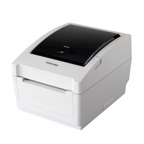
1. OUTLINE EO18-33025 1.1 Feature of the B-EV4D/EV4T 1. OUTLINE 1.1 Feature of the B-EV4D/EV4T 1.1.1 Front View (1) B-EV4D STATUS Lamp Media View Window FEED Button Top Cover Release Button Media Outlet SD Card Slot Cover SD Card Slot (2) B-EV4T STATUS Lamp Media View Window... -
Page 4: Rear View
1. OUTLINE EO18-33025 1.1 Feature of the B-EV4D/EV4T 1.1.2 Rear View Fanfold paper slot Ethernet interface USB Interface Connector Power Switch Parallel Interface Connector (Centronics) Power Jack Serial Interface Connector (RS-232C) 1.1.3 Interior (1) B-EV4D Print Head Top Cover Media Holder Feed Gap Sensor (Receiver) Media Holder Lock Switch... - Page 5 1. OUTLINE EO18-33025 1.1 Feature of the B-EV4D/EV4T (2) B-EV4T Ribbon Access Cover Ribbon Rewind Gear Print Head Top Cover Feed Gap Sensor (Receiver) Spring Guide Wheel (Take-up side) Media Holder Media Holder Spring Guide Wheel (Supply side) Lock Switch Media Guide Cover Open Sensor...
-
Page 6: Indications Of The Model Name
1. OUTLINE EO18-33025 1.2 Indication of the Model Name 1.2 Indication of the Model Name B - E V 4 D - G S 14 - QM - R RoHS compliance model Destination country/Region code QM: Standard for World Wide Interface 14: USB, Serial, Parallel and Ethernet Issue mode... -
Page 7: Basic Specifications
1. OUTLINE EO18-33025 1.3 Basic Specifications 1.3 Basic Specifications Model B-EV4D B-EV4T Construction Double walled casing & Clam shell design General Maintenance No tool required to repair thermal head and platen Characteristics Paper holder No roll spindle & No paper holder spring Direct thermal printing Direct thermal/thermal transfer Printer... - Page 8 1. OUTLINE EO18-33025 (Revision Date: Mar. 27, 2009) 1.3 Basic Specifications Model B-EV4D B-EV4T Printer Bitmap: Alpha-numeric 20 types + Kanji 4 types characteristics Fonts Outline: 2 types Writable characters, Optional TTF One LED w/ 3 colors (w/ silk screen print of “STATUS”) Feed key (w/ silk screen print of “...
- Page 9 1. OUTLINE EO18-33025 1.3 Basic Specifications Model B-EV4D B-EV4T Width 7.8” (198 mm) 7.8” (198 mm) Physical Height 6.7” (169.5 mm) 6.8” (173 mm) characteristics Depth 10.2” (258 mm) 10.2” (258 mm) Weight 2.5Kg or less 2.5Kg or less Related products Options Full cutter module (B-EV204-F-QM-R) Partial cutter module (B-EV204-P-QM-R)
-
Page 10: Key And Led
1. OUTLINE EO18-33025 1.4 Key and LED 1.4 Key and LED STATUS Lamp FEED Button The [FEED] button operates as FEED button or PAUSE button depending on the printer statuses. Pressing this button when the printer is in online state causes a media feed. As the FEED button Pressing this button after removing a cause of an error returns the printer to online state. -
Page 11: Supply Specifications
1. OUTLINE EO18-33025 1.5 Supply Specifications 1.5 Supply Specifications 1.5.1 Media Type The table below shows the size and shape of the media that can be used on this printer. Black Mark Black Mark Tag paper Label (on reverse side) (on reverse side) Cut position Feed Direction... -
Page 12: Detection Area Of The Transmissive Sensor
1.5 Supply Specifications NOTES: To ensure print quality and print head life use only TOSHIBA TEC approved media. When using a media roll of 76.2-mm (3”) inner core diameter, the 3”-Diameter Media Shaft included in the optional External Media Roll Hanger is required. -
Page 13: Ribbon
Outside NOTES: To ensure print quality and print head life use only TOSHIBA TEC specified ribbons. Too much difference in width between media and ribbon may cause ribbon wrinkles. To avoid ribbon wrinkles use a ribbon for proper media width shown in the above table. Do not use a ribbon that is narrower than media. -
Page 14: Electronic Specifications
2. ELECTRONICS SPECIFICATIONS EO18-33025 2.1 Block Diagram 2. ELECTRONIC SPECIFICATIONS 2.1 Block Diagram... -
Page 15: Main Pc Board Layout
2. ELECTRONICS SPECIFICATIONS EO18-33025 2.2 Main PC Board Layout 2.2 Main PC Board Layout U12: Serial Interface Controller JP7: Serial (RS-232C) JP4: Parallel (Centronics) DC Jack JP9: USB SW1: Power Switch JP3: Ethernet (10BASET/100BASETX) JP12: Print Head GS model: 203dpi Ground Terminal JP30: Print Head TS model: 300dpi... -
Page 16: Description Of The Main Pc Board
2. ELECTRONICS SPECIFICATIONS EO18-33025 2.3 Description of the Main PC Board 2.3 Description of the MAIN PC Board This PC board, the brain of the printer, is comprised of the following components. 32bit RISC CPU (U2): Type: AT91SAM9260 The 32bit RISC CPU operates the following processing: Controlling the interfaces •... - Page 17 2. ELECTRONICS SPECIFICATIONS EO18-33025 2.3 Description of the Main PC Board DC/DC Converter (U22, 23): Type: TS34063 It generates the voltages (+5V, +3.3V) from the power supply voltage (AC adapter). +5V and +3.3V are used as the operating voltage for each circuit. Eternet Transceiver (U8): Type: DM9161 This IC is used for controlling the Ethernet (10BASET/10BASETX).
- Page 18 2. ELECTRONICS SPECIFICATIONS EO18-33025 2.3 Description of the Main PC Board JP2 (SD Card Slot): Type: MS3B11-KAA-0 This connector is connected to the SD Card. Note: Recommended SD card specification. Signal • Supported DOS FAT file system. CD/DAT3 • Folders stored in the SD card should be in the 8.3 filename format. VSS1 •...
- Page 19 2. ELECTRONICS SPECIFICATIONS EO18-33025 2.3 Description of the Main PC Board JP4 (Parallel Interfcae): This connector is used for the Parallel (Centronics) interface. SPP Mode Nibble Mode Function Signal A low on this line indicates that there are valid data at the host. When this Strobe Strobe pin is de-asserted, the +ve clock edge...
- Page 20 2. ELECTRONICS SPECIFICATIONS EO18-33025 2.3 Description of the Main PC Board JP9 (USB): Type: Type B Connector This connector is used for the USB interface. Signal +5 V JP12 (Print Head): This connector is connected to the print head (for GS model, 203dpi). The voltages and signals for controlling the print head are input/output JP12-1 into/from the connector.
- Page 21 2. ELECTRONICS SPECIFICATIONS EO18-33025 2.3 Description of the Main PC Board JP14 (Stepping Motor): This connector is connected to the Stepping Motor. Signal MB (PHASE1) MA (PHASE1) MB (PHASE2) MA (PHASE2) JP16 (Cover Open Sensor): This connector is connected to the Cover Open Sensor. Signal +3.3V HEAD...
- Page 22 2. ELECTRONICS SPECIFICATIONS EO18-33025 2.3 Description of the Main PC Board JP24 (Stepping Motor Thermistior): This connector is connected to the Stepping Motor Thermistor. MOTOR TEMP signal is temperature of the stepping motor. Signal MOTOR TEMP JP28 (Feed Key/Status LED): This connector is connected to the Feed Key and Status LED.
-
Page 23: Replacing The Important Parts
It is also necessary to wipe off excessive oil as it collects dirt. NOTE: Before replacing the important parts, store the printer parameter data on a PC with the B-EV4 setting tool. Uploading the data from the PC to the printer after replacement restores the printer parameter setting to the status prior to replacement. -
Page 24: Replacing The Top Cover
3. REPLACING THE IMPORTANT PARTS EO18-33025 (Revision Date: Mar. 27, 2009) 3.1 Replacing the Top Cover 3.1 Replacing the Top Cover 3.1.1 B-EV4T model 1. Press down the top cover release button to unlock the top cover, then fully open the top cover. -
Page 25: B-Ev4D Model
3. REPLACING THE IMPORTANT PARTS EO18-33025 (Revision Date: Mar. 27, 2009) 3.1 Replacing the Top Cover 4. Remove the top cover. 5. Replace the top cover with a new one, then reassemble in the reverse order of removal. Top Cover 3.1.2 B-EV4D model 1. - Page 26 3. REPLACING THE IMPORTANT PARTS EO18-33025 (Revision Date: Mar. 27, 2009) 3.2 Replacing the Lower Cover 3. Release the media view window hooks which hold the top cover together with the top inner cover. Hook Top Inner Cover Top Cover Media View Window 4.
- Page 27 3. REPLACING THE IMPORTANT PARTS EO18-33025 (Revision Date: Mar. 27, 2009) 3.2 Replacing the Lower Cover 5. Disconnect the connector from the feed button PC board. Feed Button PC Board Connector 6. Remove the top cover. 7. Replace the top cover with a new one, then reassemble in the reverse order of removal.
-
Page 28: Replacing The Lower Cover
3. REPLACING THE IMPORTANT PARTS EO18-33025 (Revision Date: Mar. 27, 2009) 3.2 Replacing the Lower Cover 3.2 Replacing the Lower Cover 1. Turn the printer upside down and use the Phillips screwdriver to remove the 6 screws. 2. Remove the lower cover. Lower Cover T-3x12 Screw 3. -
Page 29: Replacing The Main Pc Board
3. REPLACING THE IMPORTANT PARTS EO18-33025 (Revision Date: Mar. 27, 2009) 3.3 Replacing the Main PC Board 3.3 Replacing the Main PC Board 1. Refer to section 3.2 to remove the lower cover. 2. Remove the screw from the main PC board. 3. - Page 30 6. Replace the main PC board with a new one, then reassemble in the reverse order of removal. After replacement, perform the following operations. ● Perform a media sensor calibration with the button of the printer or B-EV4 Setting Tool. Regarding the media sensor calibration, refer to the Owner’s Manual or the B-EV4 Setting Tool Specification posted on the Barcode Knowledge Pot.
-
Page 31: Replacing The Platen Ass'y
3. REPLACING THE IMPORTANT PARTS EO18-33025 (Revision Date: Mar. 27, 2009) 3.4 Replacing the Platen Ass’y 3.4 Replacing the Platen Ass’y 1. Refer to section 3.1 to open the top cover. 2. Release the platen holder tabs from the lower inner cover and vertically raise them. 3. -
Page 32: Replacing The Print Head Ass'y
3. REPLACING THE IMPORTANT PARTS EO18-33025 (Revision Date: Mar. 27, 2009) 3.5 Replacing the Print Head Ass’y 3.5 Replacing the Print Head Ass’y CAUTION! 1. NEVER touch the element when handling the Print Head. 2. NEVER touch the connector pins to avoid a breakdown of the Print Head by static electricity. - Page 33 3. REPLACING THE IMPORTANT PARTS EO18-33025 (Revision Date: Mar. 27, 2009) 3.5 Replacing the Print Head Ass’y 4. Remove the connector from the print head ass’y. 5. Remove the print head ass’y. Connector Print Head Ass’y 6. Replace the print head ass’y with a new one, then reassemble in the reverse order of removal.
-
Page 34: B-Ev4D Model
3. REPLACING THE IMPORTANT PARTS EO18-33025 (Revision Date: Mar. 27, 2009) 3.5 Replacing the Print Head Ass’y 3.5.2 B-EV4D model 1. Refer to section 3.1 to open the top cover. 2. The print head block is secured to the top inner cover with the latches. Push both sides of the bracket and pull the print head block. - Page 35 3. REPLACING THE IMPORTANT PARTS EO18-33025 (Revision Date: Mar. 27, 2009) 3.5 Replacing the Print Head Ass’y 3. Remove the two pins which secure the print head ass’y. Print Head Ass’y 4. Remove the connector from the print head ass’y. 5.
- Page 36 3. REPLACING THE IMPORTANT PARTS EO18-33025 (Revision Date: Mar. 27, 2009) 3.5 Replacing the Print Head Ass’y 6. Replace the print head ass’y with a new one, then reassemble in the reverse order of removal. [ Print head element side ] [ Print head bracket side ] Head Element...
-
Page 37: Replacing The Stepping Motor
3. REPLACING THE IMPORTANT PARTS EO18-33025 (Revision Date: Mar. 27, 2009) 3.6 Replacing the Stepping Motor 3.6 Replacing the Stepping Motor 1. Refer to section 3.2 to remove the lower cover. 2. Disconnect the stepping motor connector from the main board. 3. - Page 38 3. REPLACING THE IMPORTANT PARTS EO18-33025 (Revision Date: Mar. 27, 2009) 3.6 Replacing the Stepping Motor 5. Replace the stepping motor with a new one, then reassemble in the reverse order of removal. Be sure to apply FLOIL to the gear when reassembling. LUBRICATION Gear: FLOIL NOTE:...
-
Page 39: Replacing The Gear Cover
3. REPLACING THE IMPORTANT PARTS EO18-33025 (Revision Date: Mar. 27, 2009) 3.7 Replacing the Gear Cover 3.7 Replacing the Gear Cover 1. Refer to section 3.2 to remove the lower cover. 2. Use the Phillips screwdriver to remove the 4 screws. 3. - Page 40 3. REPLACING THE IMPORTANT PARTS EO18-33025 (Revision Date: Mar. 27, 2009) 3.7 Replacing the Gear Cover 5. Replace the gear cover and the each gears with a new one, then reassemble in the reverse order of removal. Be sure to apply FLOIL to the gear when reassembling. 3-18...
-
Page 41: Replacing The Feed Button Pc Board
3. REPLACING THE IMPORTANT PARTS EO18-33025 (Revision Date: Mar. 27, 2009) 3.8 Replacing the Feed Button PC Board 3.8 Replacing the Feed Button PC Board 1. Refer to section 3.1 to remove the top cover. 2. Remove the screws which fix the feed button PC board and the mylar sheet to the mechanism. -
Page 42: Replacing The Cover Open Sensor
3. REPLACING THE IMPORTANT PARTS EO18-33025 (Revision Date: Mar. 27, 2009) 3.9 Replacing the Cover Open Sensor 3.9 Replacing the Cover Open Sensor 1. Refer to section 3.1 to remove the top cover. 2. Remove the sensor connector from the main PC board. Main PC Board Sensor Connector (JP16) 3. -
Page 43: Replacing The Ribbon Sensor
3. REPLACING THE IMPORTANT PARTS EO18-33025 (Revision Date: Mar. 27, 2009) 3.10 Replacing the Ribbon Sensor (B-SV4T model only) 3.10 Replacing the Ribbon Sensor (B-SV4T model only) 1. Refer to section 3.1 to remove the top cover. 2. Remove the sensor connector from the main PC board. Main PC Board Sensor Connector (JP20) 3. -
Page 44: Replacing The Black Mark Sensor
3. REPLACING THE IMPORTANT PARTS EO18-33025 (Revision Date: Mar. 27, 2009) 3.11 Replacing the Black Mark Sensor 3.11 Replacing the Black Mark Sensor 1. Refer to section 3.1 to remove the top cover. 2. Remove the sensor connector from the main PC board. 3. - Page 45 B-EV4 Setting Tool. Failure to do this may cause a sensor error. Regarding the calibration with the button of the printer, refer to the Owner’s Manual. Regarding the calibration with the B-EV4 Setting Tool, refer to the B-EV4 Setting Tool Specification posted on the Barcode Knowledge Pot.
-
Page 46: Replacing The Feed Gap Sensor (Lower)
3. REPLACING THE IMPORTANT PARTS EO18-33025 (Revision Date: Mar. 27, 2009) 3.12 Replacing the Feed Gap Sensor (Lower) 3.12 Replacing the Feed Gap Sensor (Lower) 1. Refer to section 3.1 to remove the top cover. 2. Use the Phillips screwdriver to remove the 2 screws from the mylar sheet. 3. - Page 47 Failure to do this may cause a sensor error. Regarding the calibration with the button of the printer, refer to the Owner’s Manual. Regarding the calibration with the B-EV4 Setting Tool, refer to the B-EV4 Setting Tool Specification posted on the Barcode Knowledge Pot.
-
Page 48: Replacing The Feed Gap Sensor (Upper)
3. REPLACING THE IMPORTANT PARTS EO18-33025 (Revision Date: Mar. 27, 2009) 3.13 Replacing the Feed Gap Sensor (Upper) 3.13 Replacing the Feed Gap Sensor (Upper) 1. Refer to section 3.1 to remove the top cover. 2. Refer to section 3.2 to remove the lower cover. 3. - Page 49 Failure to do this may cause a sensor error. Regarding the calibration with the button of the printer, refer to the Owner’s Manual. Regarding the calibration with the B-EV4 Setting Tool, refer to the B-EV4 Setting Tool Specification posted on the Barcode Knowledge Pot.
-
Page 50: Troubleshooting
4. TROUBLESHOOTING EO18-33025 4.1 LED Status 4. TROUBLESHOOTING The following guide lists the most common problems that might be encountered when operating this bar code printer. If the printer still does not function after all suggested solutions have been invoked, please contact the Customer Service Department of your purchased reseller or distributor for assistance. -
Page 51: Print Quality
4. TROUBLESHOOTING EO18-33025 4.2 Print Quality 4.2 Print Quality Problem Possible Cause Recovery Procedure Check if interface cable is well Re-connect cable to interface. connected to the interface connector. The serial port cable pin configuration Please replace the cable with pin to pin is not pin to pin connected. -
Page 52: Maintenance
5. MAINTENANCE EO18-33025 5. MAINTENANCE 5. MAINTENANCE WARNING! DO NOT USE a spray cleaner containing flammable gas for cleaning this product, as this may cause a fire. This section presents the clean tools and methods to maintain your printer. 1. Please use one of following material to clean the printer. •... - Page 53 5. MAINTENANCE EO18-33025 5. MAINTENANCE Notes: Do not touch printer head by hand. If you touch it careless, please use ethanol to clean it. Please use 100% Ethenol. DO NOT use medical alcohol, which may damage the printer head. Regularly clean the print head and supply sensors once change a new ribbon to keep printer performance and extend printer life.
-
Page 54: Firmware Download Mode
6.1 FIRMWARE DOWNLOAD 6. SYSTEM MODE When the [FEED] button is held and the B-EV4 series is turned on, the printer is ready to start the system mode. As the STATUS lamp turns in the following order every 1.5 seconds, release the [FEED] button while the STATUS lamp indicates your desired mode to go into it. -
Page 55: Parameter Clear
6. SYSTEM MODE EO18-33025 (Revision Date: Mar. 27, 2009) 6.2 ABORT OF LABEL FORMAT AUTO CALL 6.2 ABORT OF LABEL FORMAT AUTO CALL When the STATUS lamp blinks in orange during the system mode, releasing the [FEED] button aborts a label format auto call. -
Page 56: Sensor Adjustment
[ 0 KB][ 0 KB] EXT CHAR AREA [ 0 KB][ 0 KB] BASIC AREA [ 0 KB][ 0 KB] PC SAVE AREA [ 704 KB][ 0 KB] INFORMATION B-EV4-Gx-QM 00000000001 TOTAL FEED 0.0 km TOTAL PRINT 0.0 km TOTAL CUT IP ADDRESS 192.168.10.20... - Page 57 PRINTED IN JAPAN EO18-33025...