Sign In
Upload
Manuals
Brands
Agilent Technologies Manuals
Inverter
33120A
Agilent Technologies 33120A Manuals
Manuals and User Guides for Agilent Technologies 33120A. We have
5
Agilent Technologies 33120A manuals available for free PDF download: User Manual, Service Manual, Quick Manual, Installation Instructions Manual
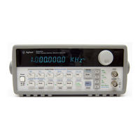
Agilent Technologies 33120A User Manual (313 pages)
15 MHz Function / Arbitrary Waveform Generator
Brand:
Agilent Technologies
| Category:
Inverter
| Size: 4.13 MB
Table of Contents
Convenient Bench-Top Features
3
Flexible System Features
3
The Front Panel at a Glance
4
Front-Panel Number Entry
5
Edit Menu
6
Modulation MENU
6
SWP (Sweep) MENU
6
The Front-Panel Menu at a Glance
6
Display Annunciators
7
The Rear Panel at a Glance
8
Table of Contents
11
Chapter 1 Quick Start
15
Quick Start
16
To Prepare the Function Generator for Use
17
Check the List of Supplied Items
17
Connect the Power Cord and Turn on the Function Generator
17
Perform a Complete Self Test
17
If the Function Generator Does Not Turn on
18
Remove the Power Cord
19
To Adjust the Carrying Handle
20
Bench-Top Viewing Positions
20
Carrying Position
20
To Set the Output Frequency
21
Enable the Frequency Modify Mode
21
Set the Units to the Desired Value
21
To Set the Output Amplitude
22
Enable the Amplitude Modify Mode
22
To Set a DC Offset Voltage
23
To Set the Duty Cycle
24
To Output a Stored Arbitrary Waveform
25
To Output a DC Voltage
26
To Store the Instrument State
27
To Rack Mount the Function Generator
29
Chapter 2 Front-Panel Menu Operation
31
Front-Panel Menu Operation
32
Front-Panel Menu Reference
33
A Front-Panel Menu Tutorial
35
Messages Displayed During Menu Use
36
Top of Menu
36
Menus
36
To Select the Output Termination
42
To Output a Modulated Waveform
43
To Output an FSK Waveform
46
To Output a Burst Waveform
49
To Output a Frequency Sweep
51
To Trigger a Burst or Sweep
53
To Turn off the Comma Separator
54
Chapter 3 Features and Functions
55
Features and Functions
56
Output Configuration
57
Output Function
57
Output Frequency
59
Output Amplitude
61
DC Offset Voltage
64
Output Units
66
Output Termination
67
Duty Cycle
68
SYNC Signal
70
Instrument State Storage
71
Amplitude Modulation (AM)
73
To Select am Modulation
73
Carrier Waveform Shape
74
Carrier Frequency
74
Modulating Waveform Shape
75
Modulating Waveform Frequency
76
Modulation Depth
76
Modulating Source
77
Frequency Modulation (FM)
78
To Select FM Modulation
78
Peak Frequency Deviation
82
Burst Modulation
83
Burst Trigger Source
84
Burst Source
85
To Select Burst Modulation
86
Burst Carrier Frequency
86
Burst Count
89
Burst Rate
90
Burst Phase
91
Frequency-Shift Keying (FSK) Modulation
92
To Select FSK Modulation
92
FSK Carrier Frequency
93
FSK “Hop” Frequency
94
FSK Rate
95
FSK Source
95
Frequency Sweep
96
To Select Sweep Modulation
96
Start Frequency and Stop Frequency
97
Sweep Time
98
Sweep Mode
98
Sweep Trigger Source
99
Triggering
100
Trigger Source Choices
101
Single Triggering in the Single Trigger Mode
102
Ext Trig / FSK / Burst Input Terminal
104
Arbitrary Waveforms
105
Creating and Storing an Arbitrary Waveform
105
Additional Information on Arbitrary Waveforms
110
System-Related Operations
111
Power-Down Recall Mode
111
Error Conditions
112
Self-Test
113
Display Control
114
Comma Separators
115
Firmware Revision Query
115
Remote Interface Configuration
116
GPIB Address
116
Remote Interface Selection
117
Baud Rate Selection
118
Parity Selection
118
Programming Language Query
119
SCPI Language Version Query
119
Calibration Overview
120
Calibration Security
120
To Unsecure for Calibration You Can Unsecure the Function
121
Calibration Count
123
Calibration Message
124
Power-On and Reset State
125
Chapter 4 Remote Interface Reference
127
Remote Interface Reference
128
SCPI Command Summary
129
The Apply Commands
129
Output Configuration Commands
130
Modulation Commands
131
Frequency-Shift Keying (FSK) Commands
132
Sweep Commands
132
Arbitrary Waveform Commands
133
Triggering Commands
134
System-Related Commands
134
Calibration Commands
135
RS-232 Interface Commands
135
Status Reporting Commands
136
IEEE-488.2 Common Commands
137
Simplified Programming Overview
138
Using the Apply Command
138
Using the Low-Level Commands
138
Reading a Query Response
139
Selecting a Trigger Source
139
Using the Apply Command
140
Apply Command Syntax
145
Output Configuration Commands
147
AM Modulation Commands
156
AM Overview
156
AM Commands
157
FM Modulation Commands
159
FM Overview
159
FM Commands
160
Burst Modulation Commands
162
Burst Modulation Overview
162
FSK Overview
169
Frequency-Shift Keying (FSK) Commands
169
FSK Commands
170
Frequency Sweep Commands
172
Sweep Overview
172
Arbitrary Waveform Overview
176
Function:shape USER
179
Using the IEEE-488.2 Binary Block Format
182
Triggering
188
System-Related Commands
190
Calibration Commands
195
RS-232 Interface Configuration
197
RS-232 Configuration Overview
197
RS-232 Data Frame Format
198
Connection to a Computer or Terminal
198
DTR / DSR Handshake Protocol
200
RS-232 Troubleshooting
201
RS-232 Interface Commands
202
The SCPI Status Registers
203
What Is an Event Register?
203
What Is an Enable Register?
203
The Status Byte Register
205
Bit Definitions – Status Byte Register
205
The Status Byte Summary Register Is Cleared When
205
Using Service Request
206
Using *STB? to Read the Status Byte
207
Using the Message Available Bit (MAV)
207
To Interrupt Your Bus Controller Using SRQ
207
To Determine When a Command Sequence Is Completed
208
The Standard Event Register
209
Bit Definitions – Standard Event Register
209
The Standard Event Register Is Cleared When
210
The Standard Event Enable Register Is Cleared When
210
Status Reporting Commands
211
An Introduction to the SCPI Language
213
Command Separators
215
Using the MIN and MAX Parameters
215
Querying Parameter Settings
216
SCPI Command Terminators
216
SCPI Parameter Types
217
Numeric Parameters Commands that Require Numeric Parameters
217
Halting an Output in Progress
218
To Set the GPIB Address
219
To Select the Remote Interface
220
To Set the Baud Rate
221
To Set the Parity
222
SCPI Conformance Information
223
SCPI Confirmed Commands
223
IEEE-488 Conformance Information
227
Chapter 5 Error Messages
229
Error Messages
230
Execution Errors
231
Invalid Character
231
Syntax Error
231
Invalid Separator
231
Undefined Header
232
Invalid Character in Number
232
Exponent too Large
232
Too Many Digits
232
Invalid String Data
233
String Data Not Allowed
233
Invalid Block Data
233
Block Data Not Allowed
233
Settings Conflict; Amplitude Has Been Adjusted
234
Settings Conflict; Duty Cycle Has Been Adjusted
234
Settings Conflict; Fm Deviation Has Been Adjusted
234
Data out of Range
236
Data out of Range; Amplitude
236
Data out of Range; Frequency
236
Data out of Range; Offset
236
Illegal Parameter Value
237
Self-Test Failed
237
Too Many Errors
237
Query
237
Command Not Allowed in Local
238
Phase-Locked Loop Is Unlocked
238
Block Length Must be Even
238
State Has Not Been Stored
238
Self-Test Errors
239
Calibration Errors
240
Cal Security Disabled by Jumper
240
Cal Secured
240
Invalid Secure Code
240
Arbitrary Waveform Errors
242
Cannot Overwrite a Built-In Arb Waveform
242
Arb Waveform Name too Long
242
Specified Arb Waveform Does Not Exist
243
Cannot Delete a Built-In Arb Waveform
243
Arb Waveform Must Contain at Least 8 Points
243
Chapter 6 Application Programs
245
Application Programs
246
BASIC Language Programs
246
C Language Programs
246
Compiling and Linking a C Program
247
Quickbasic Language Programs
249
Running a Quickbasic Program
249
BASIC / GPIB (Program 1)
250
Using the Apply Command
250
C / GPIB (Program 1)
251
Using the Low-Level Commands
254
Downloading an Arbitrary Waveform over GPIB
257
Using the Status Registers
263
Downloading an Arbitrary Waveform over RS-232
269
Quickbasic / RS-232 (Program 5)
270
Chapter 7 Tutorial
273
Tutorial
274
Direct Digital Synthesis
275
Signal Imperfections
278
Creating Arbitrary Waveforms
280
Output Amplitude Control
282
Floating Signal Generators
284
Attributes of AC Signals
285
Modulation
289
Parameter Definitions
296
Equations
297
Chapter 8 Specifications
299
Waveforms
300
Frequency Characteristics
300
Signal Characteristics
300
Output Characteristics
300
Sinewave Spectral Purity
300
Modulation Characteristics
301
System Characteristics
301
Frequency Sweep
301
General Specifications
302
Product Dimensions
303
Index
305
Declaration of Conformity
311
Advertisement
Agilent Technologies 33120A Service Manual (146 pages)
15 MHz Function/Arbitrary Waveform Generator
Brand:
Agilent Technologies
| Category:
Inverter
| Size: 4.84 MB
Table of Contents
Table of Contents
11
Chapter 1 Specifications
21
Chapter 2 Quick Start
21
To Prepare the Function Generator for Use
23
If the Function Generator Does Not Turn on
24
To Adjust the Carrying Handle
26
To Set the Output Frequency
27
To Set the Output Amplitude
28
To Set a DC Offset Voltage
29
To Set the Duty Cycle
30
To Output a Stored Arbitrary Waveform
31
To Output a DC Voltage
32
To Store the Instrument State
33
To Rack Mount the Function Generator
35
Chapter 3 Front-Panel Menu Operation
37
Front-Panel Menu Reference
39
A Front-Panel Menu Tutorial
41
To Select the Output Termination
46
To Output a Modulated Waveform
47
To Unsecure the Function Generator for Calibration
49
Chapter 4 Calibration Procedures
51
Agilent Calibration Services
53
Calibration Interval
53
Time Required for Calibration
53
Automating Calibration Procedures
54
Recommended Test Equipment
54
Test Considerations
55
Performance Verification Tests
56
Frequency Verification
58
Function Gain and Linearity Verification
58
DC Function Offset Verification
59
AC Amplitude Verification
59
Amplitude Flatness Verification
62
AM Modulation Depth Verification
63
Optional Performance Verification Tests
64
Chapter 4 Calibration Procedures (Continued)
64
Calibration Security Code
66
Calibration Count
68
Calibration Message
68
General Calibration/Adjustment Procedure
69
Aborting a Calibration in Progress
71
Frequency and Burst Rate Adjustment
71
Function Gain and Linearity Adjustment
72
AC Amplitude Adjustment (High-Z)
72
Modulation Adjustment
74
AC Amplitude Adjustment (50 W )
76
DC Output Adjustment
78
Duty Cycle Adjustment
79
AC Amplitude Flatness Adjustment
79
Output Amplifier Adjustment (Optional)
82
Error Messages
83
Chapter 5 Theory of Operation
85
Block Diagram Overview
87
Output Attenuator
88
Output Amplifier
89
AM Modulation
91
Pre-Attenuator
92
Square Wave and Sync
92
Filters
94
Waveform Dac/Amplitude Leveling/Waveform RAM
95
Direct Digital Synthesis (DDS ASIC)
97
System Dacs
98
Floating Logic
99
Earth-Referenced Logic
100
Power Supplies
100
Display and Keyboard
102
Chapter 6 Service
103
Operating Checklist
105
Types of Service Available
106
Repackaging for Shipment
107
Cleaning
107
Electrostatic Discharge (ESD) Precautions
108
Surface Mount Repair
108
To Replace the Power-Line Fuse
109
To Replace the Output Protection Fuse (F801)
109
Troubleshooting Hints
110
Self-Test Procedures
112
Chapter 7 Replaceable Parts
115
Replaceable Parts
115
Chapter 8 Schematics
129
33120A Block Diagram
131
Mechanical Disassembly
132
Floating Logic Schematic
133
Digital Waveform Data Synthesis
134
System DAC Schematic
135
Waveform DAC Schematic
136
Filters Schematic
137
Sync, Square Wave, and Attenuator Schematic
138
Output Amplifier Schematic
139
Output Attenuator Schematic
140
Earth Reference Logic Schematic
141
Power Supplies Schematic
142
Display and Keyboard Schematic
143
33120-66521 Component Locator Diagram
144
33120-66502 Component Locator Diagram
145
Agilent Technologies 33120A Service Manual (140 pages)
Function Generator / Arbitrary Waveform Generator
Brand:
Agilent Technologies
| Category:
Portable Generator
| Size: 7.12 MB
Table of Contents
Table of Contents
11
Chapter 2 Quick Start
21
To Prepare the Function Generator for Use
23
To Adjust the Carrying Handle
25
To Set the Output Frequency
26
To Set the Output Amplitude
27
To Set a DC Offset Voltage
28
To Set the Duty Cycle
29
To Output a Stored Arbitrary Waveform
30
To Output a DC Voltage
31
To Store the Instrument State
32
To Rack Mount the Function Generator
34
Chapter 3 Menu Tutorial
37
Front-Panel Menu Reference
39
A Front-Panel Menu Tutorial
41
To Select the Output Termination
46
To Oulput a Modulated Waveform
47
To Unsecure the Function Generator for Calibration
49
Chapter 4 Calibration Procedures
51
Hewlett-Packard Calibration Services
53
Calibration Interval
53
Time Required for Calibration
53
Automating Calibration Procedures
54
Recommended Test Equipment
54
Test Considerations
55
Performance Verification Tests
56
Frequency Verifi~Ation
58
Function Gain and Linearity Verification
58
Frequency Verification
58
DC Function Offset Verification
59
AC Amplitude Verification
59
DC Function Oftset Verification
59
Amplitude Flatness Verification
62
AM Modulation Depth Verification
63
Optional Performance Verification Tests
64
Chapter 4 Calibration Procedures
64
Calibration Security Code
66
Calibration Count
68
Calibration Message
68
General Calibration~A4Justment Procedure
69
Function Gain and Linearity Adjustment
70
AC Amplitude Adjustment (High Z)
70
Modulation Adjustment
72
AC Amplitude Adjustment
73
AC Amplitude Adjustment (50 Q )
73
DC Output Adjustment
76
Duty Cycle Adjustment
77
AC Amplitude Flatness Adjustment
77
Output Amplifier Adjustment Ioptional)
80
Output Amplifier Adjustment
80
Error Messages
81
Chapter 5 Theory of Operation
83
Block Diagram
84
Block Diagram Overview
85
Output Attenuator
86
Output Amplifier
87
Filters
88
Ram
89
Waveform Daciamplitude Leveling/Waveform RAM
89
Direct Digital Synthesis (DDS ASIC)
91
System Dacs
92
Floating Logic
93
Earth-Referenced Logic
94
Power Supplies
94
Power Supplies
95
Display and Keyboard
96
Chapter 6 Service
97
Operating Checklist
98
Types of Service Available
98
Repackaging for Shipment
98
Electrostatic Discharge (ESD) Precautions
100
Surface Mount Repair
100
To Replace the Power-Line Fuse
101
To Replace the Output Protection Fuse (F801)
101
Troubleshooting Hints
102
Self-Test Procedures
104
Self-Test, Prnced~~Res
104
Replaceable Parts
107
Backdating
120
Schematics
121
Floating Logic Schematic
122
System DAC Schematic
122
Waveform DAC Schematic
122
Filters Schematic
122
Sync, Square Wave, and Attenuator Schematic
122
Output Amplifier Schematic
122
Earth Reference Logic Schematic
122
Power Supplies Schematic
122
Display and Keyboard Schematic
122
33120-66501 Component Locator Diagram
122
Chapter 7 Replaceable Parts
140
Backdating
140
Advertisement
Agilent Technologies 33120A Quick Manual (12 pages)
Signal Generator
Brand:
Agilent Technologies
| Category:
Inverter
| Size: 0.7 MB
Table of Contents
Table of Contents
2
Basic Controls
3
Prerequisites
4
Setting up a Sine Wave
4
Adjusting the Amplitude
5
Method 1
5
Method 2
5
Adjusting the Frequency
5
Offset
5
Wave Forms
5
Sine
5
Square
5
Triangle/Sawtooth/ Noise
5
Arb (Arbitrary) (Sinc, Neg Ramp, Exp_Rise, Exp_Fall, Cardiac)
5
Burst
7
Setting up a Sweeping Frequency
8
Modulation
8
Amplitude Modulation
8
Frequency Modulation
10
Frequency Shift Keying (FSK)
11
Saving and Recalling
12
Agilent Technologies 33120A Installation Instructions Manual (6 pages)
Brand:
Agilent Technologies
| Category:
Laboratory Equipment
| Size: 0.23 MB
Advertisement
Related Products
Agilent Technologies 346A
Agilent Technologies 346B
Agilent Technologies 346C
Agilent Technologies 33220A
Agilent Technologies Agilent 33500 Series
Agilent Technologies 33250A
Agilent Technologies 339B
Agilent Technologies 33521A
Agilent Technologies 33522A
Agilent Technologies 33210A
Agilent Technologies Categories
Measuring Instruments
Laboratory Equipment
Test Equipment
Water Pump
Power Supply
More Agilent Technologies Manuals
Login
Sign In
OR
Sign in with Facebook
Sign in with Google
Upload manual
Upload from disk
Upload from URL