Follett Symphony 25HI400A Installation & Service Manual
Ice and water dispensers
Hide thumbs
Also See for Symphony 25HI400A:
- Installation, operation and service manual (48 pages) ,
- Installation, operation and service manual (48 pages)
Table of Contents
Advertisement
Quick Links
Order parts online
www.follettice.com
25CI400A Countertop Dispenser
with SensorSAFE™ option
Following installation, please forward this manual
Ice and Water Dispensers
25CI400A/W, 25HI400A, 50CI400A/W, 50HI400A
Installation, Operation and Service Manual
25CI400A/W Lever
Countertop Dispenser
to the appropriate operations person.
801 Church Lane • Easton, PA 18040, USA
Toll free (800) 523-9361 • (610) 252-7301
Fax (610) 250-0696 • www.follettice.com
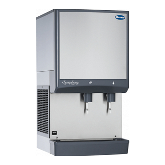
25HI400A Wall Mount Dispenser
© Follett Corporation
00187153R01
Advertisement
Table of Contents
Troubleshooting

Related Manuals for Follett Symphony 25HI400A


Summary of Contents for Follett Symphony 25HI400A
- Page 1 25CI400A/W, 25HI400A, 50CI400A/W, 50HI400A Installation, Operation and Service Manual 25CI400A/W Lever Countertop Dispenser 801 Church Lane • Easton, PA 18040, USA Toll free (800) 523-9361 • (610) 252-7301 Fax (610) 250-0696 • www.follettice.com 25HI400A Wall Mount Dispenser © Follett Corporation 00187153R01...
-
Page 2: Table Of Contents
Contents Welcome to Follett ........3 Before you begin ....... 3 Contact Information . -
Page 3: Welcome To Follett
Before you begin After uncrating and removing all packing material, inspect the equipment for concealed shipping damage. If damage is found, notify the shipper immediately and contact Follett Corporation so that we can help in the filing of a claim, if necessary. -
Page 4: Specifications
Specifications Countertop Front View 21" (534mm) 25CI400A/W 36" (915mm) 50CI400A/W 40" (1016mm) Wall mount Front View 21" (534mm) 25HI400A/W 36" (915mm) 50HI400A/W 40" (1016mm) Right Side View 24" (610mm) Condenser inlet (water- cooled only) Condenser outlet (water- cooled only) 3/4" FPT drain 2"... -
Page 5: Electrical
Electrical 115V, 60Hz, 1 phase, 14.0 amps. Connect to dedicated 20 amp circuit, fuse or breaker. Note: It is preferred that circuit be protected by a GFCI. Furnished with 7 ft (2m) power cord with a 90° NEMA hospital grade 5-20 plug. Ambient Maximum Air temp... -
Page 6: Installation
Installation Before you begin Level dispenser in both directions to ensure proper operation. Provide clearances noted in clearances table on page 5. Countertop models provide the option of taking utilities out bottom or back of dispenser. Wall mount model utilities exit through back of dispenser only. - Page 7 Fig. 4 Fig. 5 2. Disconnect the internal water line from the potable water connection fitting. 3. Remove fitting from the back wall of the dispenser (Fig. 4.1). 4. Relocate fitting to internal bulkhead and reconnect (Fig. 5.1). 6. Remove power cord strain relief (Fig. 4.2). 7.
-
Page 8: Installing Wall Mount Dispensers
Installing wall mount dispensers WARNING • Wall mount dispensers are intended to be mounted above a sink, eliminating the need for a drain pan. • Before beginning installation verify that the sink size and location meet the requirements shown in Fig. 7. • If requirements are not met, a drain pan must be used to prevent ice and water from falling on counter or floor. • FAILURE TO TAKE THESE PRECAUTIONS COULD RESULT IN SLIPS AND FALLS ON WET FLOORS Fig. 7 Minimum Sink Requirements Minimum sink requirements (without drain pan) (shown without drain pan) Front View Front View Sink centered Sink centered below dispenser below chutes... - Page 9 Fig. 10 Dispenser bottom view 10.3 10.1 10.2 7. Connect supplied 3/8" water line between water supply and water inlet fitting (Fig. 10.1). 8. Using supplied 3/4" drain tubing and barbed fittings, connect 3/4" barbed drain elbow fitting on dispenser to 3/4" FNPT drain (Fig. 10.2). 9.
-
Page 10: Icemaker Cleaning & Sanitizing
Icemaker cleaning & sanitizing Periodic cleaning of Follett’s icemaker system is required to ensure peak performance and delivery of clean, sanitary ice. The following cleaning procedures should be performed at least as frequently as recommended, and more often if environmental conditions dictate. WARNING • To reduce risk of electrical shock disconnect... -
Page 11: Start-Up Following Cleaning
20. Turn power to icemaker OFF. 21. Disconnect transport tube from evaporator outlet port. Rinse compression nozzle in clean water and reinstall on evaporator outlet. Reconnect transport tube to compression nozzle. 22. Drain any remaining sanitizing solution from evaporator. 23. Fill reservoir almost to overflowing with clean, 120 F (49 C) water, and drain. -
Page 12: Dispenser Cleaning & Sanitizing
Dispenser cleaning & sanitizing Periodic cleaning of Follett’s ice and water dispenser system is required to ensure peak performance and delivery of clean, sanitary ice. The following cleaning procedures should be performed at least as frequently as recommended, and more often if environmental conditions dictate. -
Page 13: Service
The icemaking process The Follett icemaker uses a stainless steel jacketed evaporator and operates on a continuous freezing cycle. Water is supplied to the evaporator from the water reservoir where the water level is controlled by a float valve. -
Page 14: Disassembly And Replacement Instructions
6. Remove motor assembly. Ice transport tube replacement CAUTION • Tubing must be supplied by Follett Corporation 1. Disconnect power. Remove top and partially slide icemaker out of dispenser as described on page 16. 2. Disconnect end of tube from icemaker. -
Page 15: Icemaker Removal
Icemaker removal WARNING To reduce risk of shock disconnect power before servicing. Fig. 16– All models 1. Remove front cover (Fig. 16). Fig. 17 – All models 2. Remove splash panel (Fig. 17). 25CI400A/W • 25HI400A • 50CI400A/W • 50HI400A Fig. 18 – All models 18.1 3. Lower drain pan protector (Fig. 18.1). Remove and discard shipping screw (Fig. - Page 16 Fig. 20 – Water-cooled only 20.1 7. Shut off inlet and outlet valves to water-cooled condenser and disconnect fittings (Fig. 20.1). Fig. 21 – Water-cooled only 8. Lift and position water-cooled lines into hook (Fig. 21.1). Fig. 22 – All models 22.1 22.2 9. Partially slide icemaker from dispenser (Fig. 22.1). 10.
- Page 17 Fig. 24 – Water-cooled only 24.1 13. Use hooks on icemaker electrical box to hang box on bracket (Fig. 24.1). 14. Remove icemaker from dispenser (Fig. 24.2). Fig. 25 – All models WARNING • Electrical box must be in “UP” position before supplying power •...
-
Page 18: Evaporator Disassembly
Evaporator disassembly Note: The upper bearing, lower bearing and auger assemblies must be replaced as assemblies. The bottom and top bearing assemblies cannot be field assembled to factory specifications (Fig. 26).. 1. Disconnect power to icemaker. 2. Shut off water to icemaker. 3. -
Page 19: Gearmotor Replacement
Gearmotor replacement 1. Disassemble evaporator as described above. 2. Disconnect the wire connectors. 3. Remove four screws holding gear motor mounting plate to base of icemaker and lift gearbox and motor clear of icemaker. 4. Remove machine screws holding mounting plate to motor. -
Page 20: Electrical Systems
Electrical systems WARNING To reduce risk of shock disconnect power before servicing. WARNING • Electrical box must be in “UP” position before supplying power • Start relay is gravity sensitive, and MUST be in “UP” position • Failure to comply may cause equipment to overheat, resulting in equipment failure, equipment damage or fire hazard Air-cooled icemaker... -
Page 21: Wiring Diagram - Lever Dispense Model
Wiring diagram - lever dispense model SOFTWARE SENSOR WATER LABEL RESET POWER 25CI400A/W • 25HI400A • 50CI400A/W • 50HI400A LINE DRIVE COMP I.D. I.D. EARTH RELAY START START CAPACITOR START COMP. T.O.L. -
Page 22: Wiring Diagram - Sensorsafe Model
Wiring diagram - SensorSAFE model SENSOR WATER RESET POWER LINE DRIVE COMP I.D. SOFTWARE LABEL I.D. EARTH RELAY START START CAPACITOR START COMP. T.O.L. 25CI400A/W • 25HI400A • 50CI400A/W • 50HI400A... -
Page 23: Icemaker Operational And Diagnostic Sequences
Icemaker operational and diagnostic sequences The wiring diagrams that follow illustrate the circuitry of Follett icemakers. Both normal operation (stages 1 - 6) and non-normal diagnostic sequences showing torque-out (stages 7 - 10) for use in troubleshooting are shown. Circuitry notes The icemaker receives power from two sources – the main power supply and the bin control signal power from the dispenser. -
Page 24: Normal Operation - Stage 1
Normal operation – Stage 1 Power is supplied to L1 of the control board. The ice level control in the dispenser is closed and calling for ice, supplying signal voltage to the control board. The control board will now go through the start-up sequence. Less than 30 seconds will elapse as the water sensor located in the float reservoir checks for water in the reservoir. -
Page 25: Normal Operation - Stage 3
Normal operation – Stage 3 After the initial high current draw drops off, the gearmotor start relay contacts open, dropping out the start winding. As the compressor comes up to normal running speed, the compressor start relay contacts also open, dropping out the start winding of the compressor. The icemaker is now in a normal icemaking mode. The icemaker will begin to produce ice and continue to produce ice until the bin level control in the ice dispenser is satisfied. -
Page 26: Normal Operation - Stage 5
Normal operation – Stage 5 The drive motor now shuts down and the DR LED is off. The B-T LED remains on for 20 minutes. The icemaker will not start while the B-T LED is on. To restart the icemaker for troubleshooting purposes, depress the reset button to clear the control board. -
Page 27: Diagnostic Sequence - Stage 7
Diagnostic sequence – Stage 7 The 20 minute error LED (20M) is on, indicating that the control board has sensed an over-torque condition (above 3 AMPS on the gearmotor). The 20M LED remains on for 20 minutes after an over-torque condition has occurred. The icemaker remains off as long as the 20M LED is on. When the 20M LED goes off, the control board will try to go through a normal start-up sequence. -
Page 28: Diagnostic Sequence - Stage 9
Diagnostic sequence – Stage 9 The second error (2ND) LED comes on if an over-torque condition occurs while the 60M LED is still lighted. The 2ND LED indicates that two consecutive over-torque situations have occurred. The icemaker will be shut down at this time and will not restart unless the manual reset button is depressed. -
Page 29: Refrigeration Cycle
Refrigeration cycle high pressure high side service port switch condenser filter dryer low side service port compressor evaporator high high pressure pressure pressure pressure thermostatic vapor vapor liquid liquid expansion valve 25CI400A/W • 25HI400A • 50CI400A/W • 50HI400A... -
Page 30: Refrigeration Data
1. Non-contaminated refrigerant removed from any 2. In the event of system contamination (for example, production capacity/ 24 hr. period 3. Follett Corporation does not approve of recovered Evacuation Evacuate the system to a level of 500 microns. When 90 F... -
Page 31: Dispenser Troubleshooting
Dispenser troubleshooting Before calling for service 1. Check for ice in the ice storage area. 2. Check that congealed ice is not causing a jam. 3. Check that all switches and circuit breakers are on. 4. Check that all drains are clear. Lever model troubleshooting guide Problem Does not dispense ice. -
Page 32: Icemaker Troubleshooting
WTR LED. 1. Clean or replace filter, clean condenser. 2. Remove obstruction. 3. Clean evaporator. 4. Provide proper exhaust air provisions per Follett installation manual. 5. Replace expansion valve. 6. Check for leaks; repair, evacuate, and weigh in correct charge. - Page 33 2. Check discharge pressure and adjust water regulator valve. 3. Clean or replace filter, clean condenser coil. 4. Provide inlet and exhaust air provisions per Follett icemaker installation manual. 5. Replace compressor. 1. Clean or replace filter, clean condenser coil.
-
Page 34: Dispenser Replacement Parts
Dispenser replacement parts Dispenser exterior Part # Description 501608 Baffle, ice 501614 Wheel, dispense (includes drive bar, rotating agitator, threaded bar & rod) 502821 Wheel, dispense (wheel only) 501609 Agitator, rotating 502712 Bracket, ice tube 501100 Screw 501612 Rod, threaded (includes knurled nut) 501617 Drive bar assembly (includes threaded rod and nut) 0996030... -
Page 35: Lever Models
Dispense chute and splash panel areas – lever models Part # Description 502057 Fastener, dispense chute bracket 00187682 Tube, water station 00185116 Bracket, lever 502409 Switch, dispense, ice, lever actuated (includes 502418) 502409 Switch, dispense, water, lever actuated (includes 502418) 00192864 Bracket, chute (includes fasteners 502057) 00182808 Lever, dispense 00192948 Chute and funnel, ice 00184390... -
Page 36: Dispenser Electrical Box - Lever Models
Dispenser electrical box – lever models Part # Description 500514 Thermostat 502209 Switch, dispenser power 502209 Switch, icemaker bin signal 00195818 Cord and socket (female), icemaker power 00195826 Cord and socket (female), bin signal 502336 Socket (female), icemaker power 502334 Socket (female), bin signal 502776 Power cord 25CI400A/W •... -
Page 37: Dispense Chute And Splash Panel Areas - Sensorsafe Models
Dispense chute and splash panel areas – SensorSAFE models Part # Description 502057 Fastener, dispense chute bracket 00187682 Tube, water station 00195982 Sensor, ice dispense 00195982 Sensor, water dispense 00196006 Lens, sensors 00192864 Bracket, chute (includes fasteners 502057) 502359 Clean switch, SensorSAFE (includes 501841) 00192948 Chute and funnel, ice 00184390 Chute, water 502925... -
Page 38: Dispenser Electrical Box - Sensorsafe Models
Dispenser electrical box – SensorSAFE models Part # Description 500514 Thermostat 502209 Switch, dispenser power 502209 Switch, icemaker bin signal 502242 Board, SensorSAFE 501959 Standoff, board (4 required) 00195818 Cord and socket (female), icemaker power 00195826 Cord and socket (female), bin signal 502336 Socket (female), icemaker power 502334 Socket (female), bin signal 502776... -
Page 39: Wheel Motor And Drive System
Wheel motor and drive system Part # Description 501861 Wheel motor, 120V, 60Hz 501026 Washer, thrust 501607 Fan blade, wheel motor 00182246 Chain, pitch 64, link 502692 Sprocket, drive shaft, 35T (includes 500367) 501019 Sprocket, wheel motor, 10T 501024 Bearing, drive shaft 500799 Connecting link, chain 500367 Key, drive shaft 205991... -
Page 40: Water And Drain
Water and drain Part # Description 502921 Valve, water shut off 502922 Clip, shut off valve 00134502 Elbow, 1/4" x 3/8" 502923 Tee, 1/4" 502920 Strainer 502925 Elbow, 3/8" 00184549 Drain tube, hopper 00195958 Drain, waste 00195966 Fitting, water-cooled condenser inlet 00195966 Fitting, water-cooled condenser outlet 00137315... -
Page 41: Icemaker Replacement Parts
Icemaker replacement parts Evaporator Part # Description 502735 Coupling, vee band, includes nut 502736 Bearing assembly, top 502110 Loop, ice compression, beveled 502737 Auger 502725 Evaporator (includes insulation jacket, 502740) 500496 O ring, bearing housing 502738 Bearing assembly, bottom (includes O rings and condensate shield) 501063 O ring, mounting base 500744... -
Page 42: Air-Cooled Icemakers
Air-cooled icemakers 25CI400A/W • 25HI400A • 50CI400A/W • 50HI400A... - Page 43 Part # Description 502724 Drier 00195917 Condenser coil, air-cooled 502116 Water sensor 00163824 Reservoir mounting bracket 500504 Float valve & reservoir 00187187 Reservoir overflow tube 00141440 Evaporator water feed and drain line Evaporator (see page 41 for complete breakdown) 502079 Tubing, polypropylene, reservoir supply (sold by foot) 502078 Fitting, plastic, float valve (includes sleeve &...
-
Page 44: Water-Cooled Icemakers
Water-cooled icemakers 25CI400A/W • 25HI400A • 50CI400A/W • 50HI400A... - Page 45 Part # Description 502724 Drier 500537 Valve, water regulating (includes 501810) 501810 Iso-washer (for water regulating valve) 502116 Water sensor 500504 Float valve & reservoir 00195941 Reservoir mounting bracket 502079 Tubing, polypropylene, reservoir supply (sold by foot) 502078 Fitting, plastic, float valve (includes sleeve & stem) Evaporator (see page 41 for complete breakdown) 00141440 Evaporator water feed and drain line...
-
Page 46: Icemaker Electrical Components
Icemaker electrical components Part # Description 502780 Capacitor, start, compressor, 115V, 60Hz 501588 Relay start, compressor, 115V, 60Hz 502331 Board, control circuit, 115V, 60Hz 502116 Water sensor 502392 Switch, on/off, compressor 501959 Board, stand off control (4 required) 00195834 Cord and plug (male), icemaker power 00195842 Cord and plug (male), bin signal 502235... - Page 48 Chewblet is a registered trademark of Follett Corporation, registered in the US. Follett reserves the right to change specifications at any time without obligation. Certifications may vary depending on country of origin. 801 Church Lane • Easton, PA 18040, USA Toll free (800) 523-9361 •...