Table of Contents
Advertisement
Quick Links
INSTRUCTION, OPERATING AND
MAINTENANCE MANUAL FOR
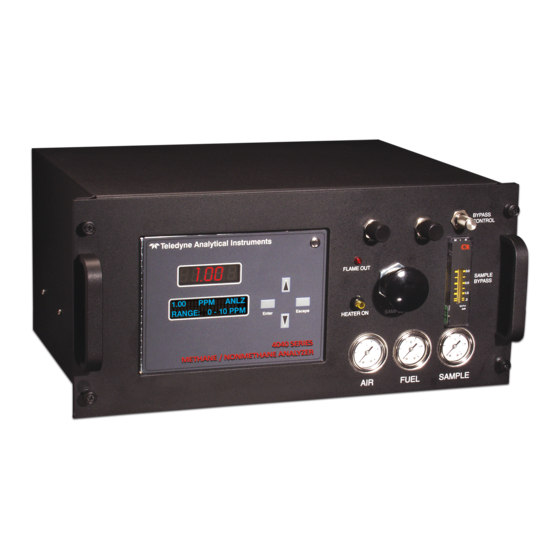
MODEL 4040
P/N M4040
ECO: #XX-XXXX
DATE 02/22/06
DANGER
Toxic and/or flammable gases or liquids may be present in this monitoring system.
Personal protective equipment may be required when servicing this instrument.
Hazardous voltages exist on certain components internally which may persist for
a time even after the power is turned off and disconnected.
Only authorized personnel should conduct maintenance and/or servicing. Before
conducting any maintenance or servicing, consult with authorized
supervisor/manager.
Teledyne Analytical Instruments
i
Advertisement
Table of Contents

Related Manuals for Teledyne 4040


Summary of Contents for Teledyne 4040
- Page 1 INSTRUCTION, OPERATING AND MAINTENANCE MANUAL FOR MODEL 4040 P/N M4040 ECO: #XX-XXXX DATE 02/22/06 DANGER Toxic and/or flammable gases or liquids may be present in this monitoring system. Personal protective equipment may be required when servicing this instrument. Hazardous voltages exist on certain components internally which may persist for a time even after the power is turned off and disconnected.
- Page 2 Any safeguards required such as locks, labels, or redundancy, must be provided by the user or specifically requested of Teledyne at the time the order is placed.
-
Page 3: Safety Messages
NOTE: Additional information and comments regarding a specific component or procedure are highlighted in the Symbol form of a note. STAND-BY: This symbol indicates that the instrument is on Stand-by but circuits are active. Teledyne Analytical Instruments... - Page 4 Manuals do get misplaced. Additional manuals can be obtained from Teledyne at the address given in the Appendix. Some of our manuals are available in electronic form via the internet. Please visit our website at: www.teledyne-ai.com.
-
Page 5: Additional Safety Information
Since the use of this instrument is beyond the control of Teledyne, no responsibility by Teledyne, its affiliates, and agents for damage or injury from misuse or neglect of this equipment is implied or assumed. - Page 6 Series 4040 system. See the procedures for purging and leak checking this instrument on the following pages. If toxic gases or other hazardous materials are introduced into the sample system, the same precautions regarding leak checking and purging apply to the sample lines and sample supply or delivery lines.
-
Page 7: Procedure For Removal Of Internal Inaccessible Shock Hazards
THIS INSTRUMENT IS DESIGNED TO BE OPERATED IN A NONHAZARDOUS AREA. THE ANALYZER USES HYDROGEN GAS AND/OR OTHER COMBUSTIBLE GASES IN ITS OPERATION. THIS EQUIPMENT, IF NOT USED AND MAINTAINED PROPERLY CAN BE AN EXPLOSION HAZARD. THE ANALYZER, Teledyne Analytical Instruments... - Page 8 PRINCIPLES OF OPERATION OF THIS EQUIPMENT ARE UNDERSTOOD BY THE USER. SINCE THE USE OF THIS INSTRUMENT IS BEYOND THE CONTROL OF TELEDYNE, NO RESPONSIBILITY BY TELEDYNE, ITS AFFILIATES AND AGENTS FOR DAMAGE OR INJURY RESULTING FROM MISUSE OR NEGLECT OF THIS INSTRUMENT IS IMPLIED OR ASSUMED.
-
Page 9: Table Of Contents
2.2.4 Flame Ionization Detection Cell 2.3 Detection Cell 2.3.1 Electrometer-Amplifier 2.3.2 Anode Power Supply 2.3.3 Flame Guard Circuit 2.3.4 Flame Ignition Circuit Installation ................... 25 3.1 Unpacking the Analyzer 3.2 Mounting the Analyzer 3.3 User Connections 3.3.1 Electrical Power Connections Teledyne Analytical Instruments... - Page 10 Series 4040 3.3.3.1 Primary Input Power 3.3.3.2 Fuse Installation 3.3.3.3 50-Pin Equipment Interface Connector 3.3.3.4 Analog Output 3.3.3.5 Alarm Relays 3.3.3.6 Digital Remote Cal Inputs 3.3.3.7 Range ID Relays 3.3.3.8 Network I/O 3.3.3.9 Pin Out Table 3.3.4 RS-232 Port 3.3.5 Supporting Gases 3.3.5.2 Effluent...
- Page 11 4.12 Span 4.13 The Alarms Function 4.14 The Range Function 4.15 Changing Stream 4.16 Analog output Adjustment 4.17 Standby 4.18 Advanced User Functions 4.18.1 Timing Appendix ..................67 Specifications and Initial Settings: Recommended Spare Parts List Drawing List Teledyne Analytical Instruments...
-
Page 12: List Of Figures
Series 4040 List of Figures Figure 1-1: 19” Rack Piping Diagram-Model 4060 ..... 22 Figure 1-2: Flame Ionization Cell........... 24 Figure 3-1: Gas Connections............27 Figure 3-2: Equipment Interface Connector Pin Arrangement..29 Figure 4-1: Front Panel View of Regulator and Gages....48... - Page 13 Table 3-5: Remote Calibration Connections........32 Table 3-6: Range ID Relay Connections ........33 Table 3-7: Pin out of 50 pin D-Sub Connector....... 33 Table 3-8: Commands via RS-232 Input ........35 Table 3-9: Required RS-232 Options ..........35 Teledyne Analytical Instruments xiii...
- Page 14 Series 4040 Teledyne Analytical Instruments...
-
Page 15: Introduction
Introduction Introduction Teledyne Analytical Instruments Series 4040, Methane/ Non- methane Analyzer, is designed to measure the quantity of variety of hydrocarbons present in the sample gas. The Analyzer is a microprocessor controlled digital instrument based on Teledyne’s highly successful Model 402R series analog Total Hydrocarbon Analyzer, coupled with a gas separation Column and a switching valve. -
Page 16: Principle Of Operation
Series 4040 1.2 Principle of Operation The sample is brought to a heated compartment (50 - 80° C per application) and into a sample loop and a 10-port, 2 position (Position A & B) switching valve. In valve Position B the carrier gas, nitrogen, pushes the sample into a Column to separate methane from the remaining hydrocarbons. -
Page 17: Introduction
Series 4040 uses a Flame Ionization Detector to sense hydrocarbons. The FID was selected based on the positive performance and extensive experience in the use of this detector in other Teledyne analyzers namely Model 402R and Model 4020. The FID has proven itself to be a rugged, stable, long life sensor giving years of trouble free operation in various applications. -
Page 18: Sample System
Operational Theory The Series 4040 Analyzer is composed of three subsystems: 1. Sample System 2. Detector Cell 3. Electronic Signal Processing, Display and Control 2.2 Sample System The Analyzer contains three (3) separate isothermal chambers controlled by individual PID temperature controllers, viewed just behind the Front Panel. - Page 19 Operational Theory Series 4040 Figure 2-1 19” Rack Piping Diagram-Model 4040 Teledyne Analytical Instruments...
-
Page 20: Gas Flow Control System
THE POWER CORD. The collector is interconnected with the electrometer-amplifier PC board by a coaxial cable. Although the cable and fittings are intended for coaxial service, the cable is actually being used as a shielded single- conductor connection. Teledyne Analytical Instruments... - Page 21 Operational Theory Series 4040 The anode-igniter, as its name implies, serves two functions. When relay K2 at PCB part number B74671 is energized, the coil becomes an electrical heating element that glows red-hot and ignites the hydrogen fuel. When relay K2 at B74671 is de-energized, the coil is connected to the +260 volt DC terminal of the anode-flame guard power supply PC board.
-
Page 22: Electrometer-Amplifier
2.3.4 Flame Ignition Circuit The flame ignition circuit includes the anode-igniter electrode (in the detector cell), a transformer, and processor controlled relay. The circuit is automatically energized when the FID cools due to lack of flame. Teledyne Analytical Instruments... - Page 23 Operational Theory Series 4040 If automatic ignition fails five times, there will be a message that reports this, and the flame can be manually ignited by pressing simultaneously the Up and Down key. Teledyne Analytical Instruments...
- Page 24 Operational Theory Teledyne Analytical Instruments...
-
Page 25: Installation
3.2 Mounting the Analyzer The Series 4040 is a general-purpose analyzer and as such is designed with (non-sealed) enclosures. It must be installed in an area where the ambient temperature is not permitted to drop below 32ºF nor rise above 100ºF. -
Page 26: User Connections
Installation Series 4040 Regardless of configuration, the analyzer/system must be installed on a level surface with sufficient space allocated on either side for personnel and test equipment access. Subject to the foregoing, the Analyzer/system should be placed as close to the sample point as is possible. -
Page 27: Figure 3-1: Gas Connections
“chasing” the red glow (and hydrocarbon deposits) down to the open end of the tube. Cap tubing while not in use with suitable non- contaminating caps. Teledyne Analytical Instruments... - Page 28 NITROGEN GAS, ULTRA ZERO GRADE WITH THC LESS THAN 0.05 PPM. 3.3.3 Electrical Connections Figure 3-1 shows the Series 4040 rear panel. There are connections for power, digital communications, and both digital and analog concentration output. For safe connections, no uninsulated wiring should be able to come in contact with fingers, tools or clothing during normal operation.
-
Page 29: Primary Input Power
(0-1 VDC, and 4-20mA DC). Each pair (1 and 3 ), (2 and 4 ) of outputs may be sourced to 1 of 4 possible measurements: % of Range for CH4. % of Range for NMH. Teledyne Analytical Instruments... -
Page 30: Alarm Relays
Installation Series 4040 % of Range for THC (THC – Total Hydrocarbon is the summation of the CH4 and NMH values). Waveform. Waveform is the FID detection level updated 10 times each second. The output is compared against the maximum input for the Analog to Digital Conversion hardware and scaled to a 0-1VDC (or 4-20mA DC) output. -
Page 31: Table 3-4: Alarm Relay Contact Pins
Can be set to trigger by levels of CH4, NMH, or THC. System Alarm: Actuates when power is removed from analyzer. It is triggered if 4040 fails to ignite after five times. Note: (Reset by pressing the STANDBY button to remove power. Then press STANDBY again and any other button except SYSTEM to resume. -
Page 32: Digital Remote Cal Inputs
Installation Series 4040 3.3.3.6 D IGITAL EMOTE NPUTS The digital remote calibration input accepts 0 V (off) or 24 V dc (on) for remote control of calibration. (See Remote Calibration Protocol below.) See Table 3-5 for pin connections. Floating input. A 5–24 V input across the + and – pins puts the Span: analyzer into the Span mode. -
Page 33: Range Id Relays
1 ID, Medium range is assigned to Range 2 ID, and High range is assigned to Range 3 ID. Table 3-6 lists the pin connections. Contacts are normally open, and they close when 4040 switches to that particular range. Table 3-6: Range ID Relay Connections... - Page 34 Installation Series 4040 Remote Span + Remote Span - Span Solenoid Return Span Solenoid Hot Range 3 Contact Range 3 Contact Alarm 3 C Contact Range 1 Contact Range 2 Contact - Output 0-1 v (Channel 2) + Output 0-1 v (Channel 1)
-
Page 35: Rs-232 Port
Section 4.1: Equipment) will be required to operate the analyzer. The recommended composition of these gases is specified in the Application Data section of the Appendix. The gases should be supplied from cylinders that are equipped with the type of regulator specified in the aforementioned sections. Teledyne Analytical Instruments... - Page 36 Installation Series 4040 CAUTION: UNDER NO CIRCUMSTANCES SHOULD YOU EMPLOY A REGULATOR THAT IS NOT EQUIPPED WITH A METALLIC DIAPHRAGM ANYWHERE IN THE SYSTEM. The regulators should be inspected prior to installation to be sure that they are oil-free. Failure to comply with these directives will result...
-
Page 37: Effluent
Warm up time is set by the software at the factory but may be overridden by pressing the <ENTER> key. DO NOT attempt to ignite the flame during warm up countdown. Condensation will occur. Teledyne Analytical Instruments... -
Page 38: Activating The Support Gases
Installation Series 4040 3.5 Activating the Support Gases 3.5.1 Air 1. Set the air tank regulator to 30 psig. 2. Adjust the Analyzer Air regulator until the air pressure gauge reads the recommended air pressure of 9 psig. After the air is flowing through the sensor and warm-up time has been completed, activate the following gases: 3.5.2 Carrier Gas... -
Page 39: Flame Ignition
See Figure 4-1. The Series 4040 will automatically attempt a flame ignition sequence following the warm up period, which has been preset at the factory. -
Page 40: Ignition And/Or Flame Guard Circuit Failure
Installation Series 4040 display: flame failure, check air, fuel and the flame failure LED will be on. 3. Open the cylinder supply valve and re-ignite the flame by pushing the up and down buttons simultaneously. 3.6.2 Ignition and/or Flame Guard Circuit Failure... - Page 41 Installation Teledyne Analytical Instruments...
- Page 42 Operation Series 4040 Teledyne Analytical Instruments...
-
Page 43: Operation
It will go through a warm-up period, followed by a diagnostic self-test routine. Note: The 4040 is always either analyzing or in a span calibration. The analysis has 2 phases, the CH4 phase and the NMH phase, as does the span calibration. -
Page 44: Default Parameters
Operation Series 4040 4.2 Default Parameters The versatility of this analyzer usually results in significant changes being made to parameters over the course of time to better suit a particular application. Occasionally processes change requiring alteration to alarms, ranges etc. At some time, it may be beneficial to reset the analyzer to the default conditions as it was when shipped from the factory. -
Page 45: Navigation And Data Entry
ON/OFF, YES/NO, or ENABLE/DISABLE type values. 4.4.2 ENTER The ENTER key is used in several context-sensitive ways. 2. When showing the CH4/NMH analysis modes, the ENTER key toggles the LINE 2 display. LINE 2 display mode 1 data: - Current analysis mode Teledyne Analytical Instruments... -
Page 46: Escape
Operation Series 4040 - Dynamic (real time) FID input level - Time spent in mode - Range - Activity indicator LINE 2 display mode 2 data: - Current analysis mode - Analysis TOTAL AREA from most recent pass of current mode. -
Page 47: Menu Structure
The value will revert to the original before modification (if any). 4.5 Menu Structure The 4040 screen setup consists of several classes of screens and items. No item occupies more than 1 line. It is important to read and understand the NAVIGATION AND DATA ENTRY section to fully understand the menu structure. -
Page 48: Main Menus
Used to define and/or start an automatic calibration AUTO-CAL: sequence. AUTOCAL is not available for standard configurations of the 4040. Used to change the amplification of the incoming signal. GAIN: This is factory set, and should not change. Used to establish password protection or change PASSWORD: the existing password. -
Page 49: Expanded Menus
Span in 7 days Span in 12 hours ----------------------- PASSWORD ----------------------- Enter Password 'T' 'A' 'I' ----------------------- GAIN ADJUST ----------------------- GAIN 1 ----------------------- ----------------------- Password Incorrect Change Password ----------------------- ----------------------- Enter New Password 'T' 'A' 'I' ----------------------- ----------------------- Teledyne Analytical Instruments... - Page 50 ----------------------- Password Mismatch ----------------------- Password Changed! ----------------------- LOGOUT ----------------------- Restrict Access? ENTER-YES ESCAPE-NO ----------------------- MODEL ----------------------- 4040 HC Monitor V2.0 8/22/05 ----------------------- SELF TEST ----------------------- Begin Self-Test? ENTER-YES ESCAPE-NO ----------------------- ----------------------- Running Diagnostic - Test - Test DAC A - Test...
- Page 51 AL-1 HIGH AL-1 NON-FAILSAFE AL-1 NON-LATCHING AL-1 20.00 ppm AL-1 SOURCE CH4 AL-2 DEFEATED AL-2 HIGH AL-2 NON-FAILSAFE AL-2 NON-LATCHING AL-2 50.00 ppm AL-2 SOURCE CH4 ----------------------- RANGE ----------------------- Range Select: Auto AutoRange Src: CH4 Man Rng: Teledyne Analytical Instruments...
- Page 52 Operation Series 4040 R1: 0-10.00ppm R2: 0-100.00ppm R3: 0-1000.00ppm ----------------------- ANALOG-OUT ADJUST ----------------------- CH1 mA Offset: CH1 mA Gain: CH1 Select: CH2 Select: ----------------------- CHANGE STREAM ----------------------- STREAM: ANALYZE ----------------------- TIMING ----------------------- CH4 I/P: 50%/50% CH4 TIME: 02m30s CH4 I Begin: 00m40s...
-
Page 53: Setting Up An Auto-Cal
The gain has been set at the factory such that the analyzer will work reliably within the prescribed range of operation. The user may change the gain when a different level of sample is to be analyzed. Teledyne Analytical Instruments... -
Page 54: Password Protection
Operation Series 4040 To setup the GAIN 1) From the Analysis Screen, press an arrow key to enter the Setup Mode. The VFD will display the first 2 lines of functions available. ________________________________________________ -> GAIN ADJUST PASSWORD ________________________________________________ <▲▼> If the arrow is not adjacent to the GAIN ADJUST menu item, use the ▲▼... - Page 55 ENTER PASSWORD SCREEN ________________________________________________ Enter a Password 'T' 'A' 'I' ________________________________________________ <▲▼> Use the ▲▼ keys to change the letters to the proper password. <Enter> Press <Enter> to advance to the next letter Teledyne Analytical Instruments...
- Page 56 Steps back to the previously entered letter or, if on the first letter, returns to the MAIN MENU. If the correct password has been entered the 4040 now allows access to all the SUBMENU items. The 4040 next presents the CHANGE PASSWORD screen.
-
Page 57: Logging Out
The system will continue analysis, however. To log out: <▲▼> From the MAIN MENU scroll to field of LOGOUT function. <Enter> Press <Enter> to logout . The screen will display the message: ________________________________________________ Restrict Access? ENTER=Yes ESCAPE=NO ________________________________________________ Teledyne Analytical Instruments... -
Page 58: The Model Screen
It is accessed via the MAIN MENU by scrolling (▲▼> to MODEL and pressing <Enter>. 4.11 System Self-Diagnostic Test The Model 4040 has a built-in self-diagnostic testing routine. Preprogramming signals are sent through the power supply, output board, preamp board and sensor circuit. The return signal is analyzed, and at the end of the test the status of each function is displayed on the screen, either as OK or BAD. -
Page 59: Span
From the MAIN MENU, scroll down to the SPAN function. <Enter> Press <Enter> to activate the SPAN function. ________________________________________________ -> CH4 Sp: 8.00 ppm NMH Sp: 2.00 ppm Span Begin ________________________________________________ ________________________________________________ Begin Span: ENTER-YES ESCAPE-NO ________________________________________________ Teledyne Analytical Instruments... -
Page 60: The Alarms Function
4.13 The Alarms Function The Model 4040 is equipped with two alarms and a system failure alarm relay. Each alarm relay has a set of form "C" contacts rated for 3 amperes resistive load at 250 VAC. See Figure in Chapter 3, Installation and/or the Interconnection Diagram included at the back of this manual for relay terminal connections. - Page 61 TRIGGER POINT: This is the threshold at which an active alarm can enter into alarm condition. If an alarm is HIGH, ACTIVE, and set at 20.00 ppb, then when the analysis concentration is at or above 20.00 ppb an alarm condition is initiated or maintained. Teledyne Analytical Instruments...
-
Page 62: The Range Function
Operation Series 4040 SOURCE: The alarm can react to measurement levels of CH4, NMH, or THC (the sum of the previous 2). CAUTION: IT IS NOT GOOD PRACTICE TO SILENCE AN EXISTING ALARM BY SETTING THE ALARM ATTRIBUTE TO ‘DEFEAT”. THE ALARM WILL NOT AUTOMATICALLY RETURN TO “ACTIVE”... -
Page 63: Changing Stream
Use the <Enter> key to move over to the Offset field. <Enter> <▲▼> Use the UP/DOWN keys to change each digits value. <Enter> Use the <Enter> key to save the value. <Escape> Use the <Escape> key to revert to the original value. Teledyne Analytical Instruments... -
Page 64: Standby
Operation Series 4040 Use the same procedure to set the gain of the instrument. After the last digit is entered, the final <Enter> press will accept the gain value. The values entered do not have explicit units of current or voltage. -
Page 65: Advanced User Functions
Operation To exit STANDBY, scroll again to the STANDBY function and press <Enter> again. 4.18 Advanced User Functions The Model 4040 provides additional functions for tailoring the instrument to your specific application. These functions include: 20. Timing 4.18.1 Timing Timing controls the parameters of the valve and data acquisition. It is specific to the setup of the instrument and must be determined at the factory or TAI trained personnel. - Page 66 Operation Series 4040 Teledyne Analytical Instruments...
-
Page 67: Appendix
One System Alarm for AC power failure and flame out, fail safe, ‘C’ type relay contacts. Calibration Contact: Calibration Contact, ‘A’ Type Relay contact for span mode indication. RS232 Output: Provided Ambient Temp: 0 – 40º C. Install in a well ventilated area Teledyne Analytical Instruments... -
Page 68: Recommended Spare Parts List
Appendix Series 4040 Recommended Spare Parts List Qty. Description B74671 PC board, Flame guard & anode power supply B74677 PC board, Electrometer-amplifier B30927 PC board, Temperature control C75825A Micro-processor PC board A46128 Coaxial cable B-13207 Sensor Assy. C62371A Display PCB Assy. -
Page 69: Drawing List
Schematic, Flame guard, anode power supply PC board D-65506 Schematic, Back panel/Power supply PC board PC Board Assemblies B-74671 PCB Assy, anode power supply, flame guard B-74677 PCB Assy, electrometer C-75825A PCB Microprocessor C-65507A PCB power supply Teledyne Analytical Instruments...