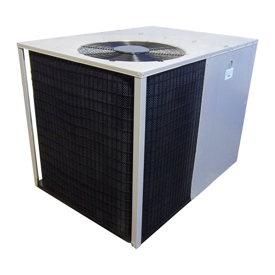
Nordyne P5RF-X48K User Manual And Installation Instructions
15 seer 2-stage r-410a single package air conditioner
Hide thumbs
Also See for P5RF-X48K:
- User manual and installation instructions (17 pages) ,
- Installation instructions manual (20 pages)
Table of Contents
Advertisement
Quick Links
15 SEER
2-Stage R-410A Single Package Air Conditioner
Single Package Air Conditioner
Read this owner information to become familiar with the capabilities and use
of your appliance. Keep this with literature on other appliances where you
have easy access to it in the future. If a problem occurs, check the instructions
and follow recommendations
given. If these suggestions don't eliminate your
problem, call your installing contractor or distributor in your area.
INTRODUCTION
Most any air conditioner will keep you cool. Our air conditioner was designed to do
it efficiently. Efficiency means less cost to you while keeping you comfortable.
WHYYOUR
AIR CONDITIONER
WORKS
SO WELL,
SO QUIETLY
1.
Air is cooled by a large evaporator coil. Moisture is also removed from the air by
this same coil.
2.
Air is then delivered through the main duct, via registers, into your home.
3.
Return air is drawn through the return register.
4.
This air enters the unit, passes through the evaporator coil, is cooled and dehumidi-
fied. Then the cycle begins again.
Advertisement
Table of Contents

Summary of Contents for Nordyne P5RF-X48K
- Page 1 15 SEER 2-Stage R-410A Single Package Air Conditioner Single Package Air Conditioner Read this owner information to become familiar with the capabilities and use of your appliance. Keep this with literature on other appliances where you have easy access to it in the future. If a problem occurs, check the instructions and follow recommendations given.
-
Page 3: Section 1. Owner Information
SECTION 1. The indoor blower will cycle on and off to maintain the indoor temperature at the desired OWNER INFORMATION heating level. OPERATING INSTRUCTIONS To Shut Off Your Air Conditioner --Set thermostat system switch to OFF and the To OperateYour Air Conditioner for Cooling-- thermostat fan switch to AUTO. -
Page 4: Section 2. Installer Information
3. For f ree airflow, make s ure your r eturn The electrical supply should be checked to de- register isnot c overed and that t he filter i s termine if adequate power is available. If there clean. is any question concerning the power supply, 4. - Page 5 a. Remove the bands from around the unit. 6ft. b. Unfold the top and bottom cap flanges. c. Carefully remove the top cap and tube. 24" CLEARANCES Minimum clearances, as specified in Figure 2, MUST be maintained from adjacent struc- tures to provide room for proper servicing and air circulation.
-
Page 6: Supply Duct
4. INSTALLTH E RETU RN AN D SU PPLY AIR REG[STER FITTINGS ON THE UNIT The supply and return fittings are included with select models. If supplied, the duct fittings are shipped in the supply duct.They attach to the unit openings with a flange and bead arrangement, secured with two sheet metal screws. -
Page 7: Typical Applications
TYPICAL APPLICATIONS ® ® SINGLE DUCT APPLICATION MULTIPLE DUCT APPLICATION Ref. No. Description 12"x 20" Return Air 16" x 20" Air Filter 12"x 20" Grille Supply Damper 14" Diameter Flex Return Duct 12" Diameter Flex Supply Duct 12" x 12" x 12" "Y" Fitting Figure 6. -
Page 8: Condensate Drain
CONNECTING THE RETURN AND SUPPLY AIR FLEXIBLE DUCTS The supply duct for all units is 12" in diam- eter. The return duct is 14" diameter for all air conditioning units. The flexible ducts can be connected to the corresponding fittings with the clamps pro- P-Trap vided with the ducts. -
Page 9: Electrical Connections
LOCATING THE THERMOSTAT Locate the thermostat away from drafts and slamming doors and place itwhere there is a free flowof air. Mount on an inside wall approximately five feet from the floor. o;i i I Do not locate near a lamp, kitchen range, direct sunlight, or in line with air flow from supply High Voltage... -
Page 10: System Operation
2 Wire Coo]inq Thermostat Stage Electd¢ Heat o_ao_ TI,er,,lostat Figure 10. Low Voltage Connections SYSTEM OPERATION Verify that the discharge air grilles are adjusted and the system is balanced. PRE-START CHECK LIST Verify that there are no air leaks in the duct work. - Page 11 Packaged Air Conditioner - Single Phase NOTES: 1. Disconnect all power before servicing. 1. Couper le courant avant de faire letretien. 2. For supply connections copper conductors only. 2. EmpIoyez uniquement conducteurs en cuivre. suitable systems that exceed 15O V to ground. 3 Ne convient installations...
- Page 12 Packaged Air Conditioner - Single Phase NOTES: 1. Disconnect all power before servicing, 1. Couper le courant avant de faire letretien. 2, For supply connections use copper conductors only, 2, EmpIoyez uniquement des conducteurs en culvre. 3, Not suita hie on systems that exceed...
- Page 13 P5RF Charging Charts PSRF-X24K Charging Chart - Cooling ve refrigerant when above curve ] "_ 460 ._/I _' 420 _- 380 "3 340 ] Add refrigerant when below curve I Liquid Temperature PSRF-X36K Charging Chart - Cooling ._-Remove refrigerant when above curve ] "_ 460 .,!' _' 420...
- Page 14 P5RF Charging Charts (continued) PSRF-X48K Charging Chart - Cooling __|veo " refrigerant when above curve ].._ "- s 460 = 420 _. 380 -o 360 •5 340 :3 320 I Add refrigerant when bel..• ........I ..Liquid Temperature PSRF-X60K Charging Chart - Cooling __[_:qove refrigerant when above curve I...
- Page 16 INSTALLER PLEASE LEAVE THESE INSTALLATION INSTRUCTIONS WITH THE HOMEOWNER. HIIiilII!!!UJL 7090800 (Replaces 709036A) Specifications and illustrations subject to change without notice and without incurring obligations. Printed in U.S.A. (09/09) O'Fallon, MO...


