Table of Contents
Advertisement
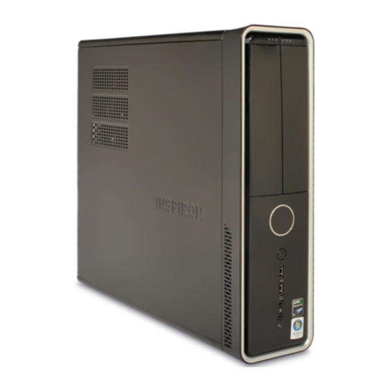
Dell™ Inspiron™ 535s/537s/545s/546s Service Manual
Technical Overview
Before You Begin
Computer Cover
Support Bracket
Front Bezel
Memory
PCI and PCI Express Cards
Drives
Models DCSLE and DCSLF
Notes, Cautions, and Warnings
NOTE:
A NOTE indicates important information that helps you make better use of your computer.
CAUTION:
A CAUTION indicates potential damage to hardware or loss of data if instructions are not followed.
WARNING:
A WARNING indicates a potential for property damage, personal injury, or death.
Information in this document is subject to change without notice.
© 2009 Dell Inc. All rights reserved.
Reproduction of these materials in any manner whatsoever without the written permission of Dell Inc. is strictly forbidden.
Trademarks used in this text: Dell, the DELL logo, and Inspiron are trademarks of Dell Inc.; Microsoft and Windows are either trademarks or registered trademarks of Microsoft
Corporation in the United States and/or other countries.
Other trademarks and trade names may be used in this document to refer to either the entities claiming the marks and names or their products. Dell Inc. disclaims any
proprietary interest in trademarks and trade names other than its own.
March 2009 Rev. A00
Fans
Front I/O Panel
Processor
System Board
Power Supply
Battery
System Setup
Advertisement
Table of Contents

Related Manuals for Dell Inspiron 535s


Summary of Contents for Dell Inspiron 535s
- Page 1 Corporation in the United States and/or other countries. Other trademarks and trade names may be used in this document to refer to either the entities claiming the marks and names or their products. Dell Inc. disclaims any proprietary interest in trademarks and trade names other than its own.
-
Page 2: Before You Begin
A component can be replaced or—if purchased separately—installed by performing the removal procedure in reverse order. Technical Specifications For information on technical specifications of your computer, see the Setup Guide that shipped with your computer or see the Dell Support website at support.dell.com. - Page 3 3. Disconnect all telephone or network cables from the computer. 4. Disconnect your computer and all attached devices from their electrical outlets. 5. Press and hold the power button while the system is unplugged to ground the system board. ...
-
Page 4: Removing The Front Bezel
WARNING: Before working inside your computer, read the safety information that shipped with your computer. For additional safety best practices information, see the Regulatory Compliance Homepage at www.dell.com/regulatory_compliance. WARNING: To guard against electrical shock, always unplug your computer from the electrical outlet before removing the cover. -
Page 5: Removing The Support Bracket
WARNING: Before working inside your computer, read the safety information that shipped with your computer. For additional safety best practices information, see the Regulatory Compliance Homepage at www.dell.com/regulatory_compliance. WARNING: To guard against electrical shock, always unplug your computer from the electrical outlet before removing the cover. -
Page 6: Replacing The Support Bracket
4 hinge tab 5 hinge 6 support bracket Replacing the Support Bracket Inspiron 535s/537s 1. Align and insert the hinges at the bottom of the support bracket into the hinge tabs located along the edge of the computer. ... -
Page 7: Removing Pci And Pci Express Cards
WARNING: Before working inside your computer, read the safety information that shipped with your computer. For additional safety best practices information, see the Regulatory Compliance Homepage at www.dell.com/regulatory_compliance. WARNING: To guard against electrical shock, always unplug your computer from the electrical outlet before removing the cover. -
Page 8: Configuring Your Computer After Removing Or Installing A Pci/Pci Express Card
3. Remove the support bracket (see Removing the Support Bracket). 4. Prepare the card for installation. See the documentation that came with the card for information on configuring the card, making internal connections, or otherwise customizing it for your computer. - Page 9 Card Entering System Setup). Entering System Setup). 2. Go to Onboard Audio 2. Go to Onboard Audio Controller and then Controller and then change the setting to change the setting to Disabled. Enabled. 3. Connect the external 3. Connect the external audio devices to the audio devices to the sound card's connectors.
-
Page 10: Removing The Battery
WARNING: Before working inside your computer, read the safety information that shipped with your computer. For additional safety best practices information, see the Regulatory Compliance Homepage at www.dell.com/regulatory_compliance. WARNING: A new battery can explode if it is incorrectly installed. Replace the battery only with the same or equivalent type recommended by the manufacturer. - Page 11 Back to Contents Page ...
-
Page 12: Removing The Computer Cover
WARNING: Before working inside your computer, read the safety information that shipped with your computer. For additional safety best practices information, see the Regulatory Compliance Homepage at www.dell.com/regulatory_compliance. WARNING: To guard against electrical shock, always unplug your computer from the electrical outlet before removing the cover. -
Page 13: Replacing The Computer Cover
Replacing the Computer Cover 1. Ensure that all cables are connected, and fold cables out of the way. 2. Ensure that no tools or extra parts are left inside the computer. 3. Align the tabs at the bottom of the computer cover with the slots located along the edge of the computer. ... -
Page 14: Removing The Processor
WARNING: Before working inside your computer, read the safety information that shipped with your computer. For additional safety best practices information, see the Regulatory Compliance Homepage at www.dell.com/regulatory_compliance. WARNING: To guard against electrical shock, always unplug your computer from the electrical outlet before removing the cover. -
Page 15: Replacing The Processor
You must position the processor correctly in the socket to avoid permanent damage to the processor and the computer when you turn on the computer. 3. If the release lever on the socket is not fully extended, move it to that position. Inspiron 535s/537s/545s... - Page 16 2 processor pin-1 indicator 3 processor 4 release lever 4. For Inspiron 535s/537s/545s, orient the front and rear alignment-notches on the processor with the front and rear alignment-notches on the socket. 5. Align the pin-1 corners of the processor and socket.
- Page 17 12. Replace the computer cover (see Replacing the Computer Cover). Back to Contents Page ...
-
Page 18: Removing A Hard Drive
WARNING: Before working inside your computer, read the safety information that shipped with your computer. For additional safety best practices information, see the Regulatory Compliance Homepage at www.dell.com/regulatory_compliance. WARNING: To guard against electrical shock, always unplug your computer from the electrical outlet before removing the cover. -
Page 19: Replacing A Hard Drive
a. Pull the securing tab upwards and slide the hard drive out and up. 1 securing tab 2 power cable 3 data cable 4 hard drive 5 shoulder screws (4) 6. Replace the support bracket (see Replacing the Support Bracket). -
Page 20: Removing A Media Card Reader
You can use the FlexBay USB cable to install a media card reader at a later time. 5. Remove the media card reader. Inspiron 535s/537s a. Press in on the securing tab on the side of the media card reader and slide it out. 1 power cable 2 FlexBay USB cable... -
Page 21: Replacing A Media Card Reader
8. Connect your computer and devices to electrical outlets, and then turn them on. Replacing a Media Card Reader 1. Follow the procedures in Before You Begin. 2. Remove the computer cover (see Removing the Computer Cover). ... -
Page 22: Removing An Optical Drive
You can use the data cable to install an optical drive at a later time. 5. Remove the optical drive. Inspiron 535s/537s a. Press in on the securing tab on the side of the optical drive and slide it out. 1 data cable 2 power cable 3 securing tab 4 shoulder screws (2) 5 optical drive ... -
Page 23: Replacing An Optical Drive
1 data cable 2 power cable 3 securing tab 4 shoulder screws (2) 5 optical drive 6. Replace the front bezel (see Replacing the Front Bezel). 7. Replace the computer cover (see Replacing the Computer Cover). ... -
Page 24: Removing The Processor Fan And Heat Sink Assembly
WARNING: Before working inside your computer, read the safety information that shipped with your computer. For additional safety best practices information, see the Regulatory Compliance Homepage at www.dell.com/regulatory_compliance. WARNING: To guard against likelihood of electric shock, laceration by moving fan blades or other unexpected injuries, always unplug your computer from the electrical outlet before removing the cover. -
Page 25: Replacing The Processor Fan And Heat Sink Assembly
3. Replace the processor fan and heat sink assembly. Inspiron 535s/537s/545s a. Align the captive screws on the processor fan and heat sink assembly to the four metal screw hole projections on the system board. b. Tighten the four captive screws that secure the processor fan and heat sink assembly to the system board. -
Page 26: Removing The Chassis Fan
1 processor fan and heat sink assembly 2 clamp lever 3 bracket projection 4 clamp grip 5 bracket 4. Connect the processor fan and heat sink assembly cable to the fan connector on the system board (see System Board Components). -
Page 27: Replacing The Chassis Fan
1 screw 2 chassis fan Replacing the Chassis Fan 1. Follow the procedures in Before You Begin. 2. Align the top and bottom chassis fan tabs with the projections in the chassis, and slide the chassis fan towards the back of the computer. 1 bottom tab 2 top tabs (2) 3 screw ... -
Page 28: Removing The Front I/O Panel
WARNING: Before working inside your computer, read the safety information that shipped with your computer. For additional safety best practices information, see the Regulatory Compliance Homepage at www.dell.com/regulatory_compliance. WARNING: To guard against electrical shock, always unplug your computer from the electrical outlet before removing the cover. - Page 29 1. Align and slide the I/O panel into the I/O panel clamp slot. 2. Replace the screw that secures the I/O panel to the chassis. 3. Connect the cables to the system board connectors. 4. Replace the hard drive (see Replacing a Hard Drive).
-
Page 30: Removing Memory
WARNING: Before working inside your computer, read the safety information that shipped with your computer. For additional safety best practices information, see the Regulatory Compliance Homepage at www.dell.com/regulatory_compliance. WARNING: To guard against electrical shock, always unplug your computer from the electrical outlet before removing the cover. -
Page 31: Recommended Memory Configuration
notch memory module CAUTION: To avoid damage to the memory module, press the memory module straight down into the connector while you apply equal force to each end of the memory module. 5. Insert the memory module into the connector until the memory module snaps into position. If you insert the memory module correctly, the securing clips snap into the cutouts at each end of the memory module. - Page 32 1 Pair A: matched pair of memory 2 Pair B: matched pair of memory modules in connectors DIMM1 and modules in connectors DIMM2 and DIMM3 DIMM4 Inspiron 546s 1 Pair B: matched pair of memory 2 Pair A: matched pair of memory modules in connectors DIMM3 and modules in connectors DIMM1 and DIMM4...
-
Page 33: Removing The Power Supply
6. Remove the three screws that secure the power supply to the computer chassis. 1 screws (3) 2 power supply 3 release latch (only for Inspiron 535s and 537s) 7. For Inspiron 535s and 537s, press down on the release latch. - Page 34 2. Replace the three screws that secure the power supply to the computer chassis. NOTE: Route the DC power cables under the chassis tabs. The cables must be properly routed to prevent the cables from being damaged. 3. Connect the DC power cables to the system board and drives. ...
-
Page 35: Entering System Setup
1. Turn on (or restart) your computer. 2. When the DELL logo appears, press <F2> immediately. NOTE: Keyboard failure may result when a key on the keyboard is held down for extended periods of time. To avoid possible keyboard failure, press and release <F2>... - Page 36 Cache Indicates the amount of installed memory. Memory Installed Indicates the amount of available memory. Memory Available Indicates the frequency of installed memory. Memory Speed Indicates the channel mode of installed memory. Memory Channel Mode Indicates the type of installed memory. System Memory Type ...
- Page 37 S1(POS); S3(STR) (S3(STR) by default). ACPI Suspend Type On; Off (On by default) Remote Wake Up Enabled; Disabled (Disabled by default). Auto Power On Auto Power On Date 0:00:00 Auto Power On Time Off; On; Last (Off by default). AC Recovery ...
- Page 38 1 MB, 8 MB (8 MB by default). Video Memory Size FIXED, DVMT (DVMT by default). DVMT Mode 128 MB, 256 MB, MAX (128 MB by default). DVMT/FIXED Memory Size Integrated Peripherals USB Controller—Enabled or Disabled (Enabled by default). USB Device Setting USB Operation Mode—High Speed;...
-
Page 39: Changing Boot Sequence For The Current Boot
Changing Boot Sequence for the Current Boot You can use this feature, for example, to tell the computer to boot from the CD drive so that you can run the Dell Diagnostics on the Drivers and Utilities media, but you want the computer to boot from the hard drive when the diagnostic tests are complete. You can also use this feature to restart your computer to a USB device such as a floppy drive, memory key, or CD-RW drive. -
Page 40: Clearing Forgotten Passwords
4. Press plus (+) or minus (–) to change the boot priority of device. Clearing Forgotten Passwords WARNING: Before working inside your computer, read the safety information that shipped with your computer. For additional safety best practices information, see the Regulatory Compliance Homepage at www.dell.com/regulatory_compliance. 1. Follow the procedures in Before You Begin. -
Page 41: Clearing Cmos Settings
Inspiron 546s 4. Remove the 2-pin jumper plug from pins 2 and 3 and fix it on pins 1 and 2. 5. Turn on the computer, wait for approximately five seconds, and then turn off the computer. If required, press and hold the power button to turn off the computer. - Page 42 Inspiron 535s/537s Inspiron 545s Inspiron 546s 4. Replace the computer cover (see Replacing the Computer Cover).
-
Page 43: Flashing The Bios
The BIOS may require flashing when an update is available or when replacing the system board. 1. Turn on the computer. 2. Locate the BIOS update file for your computer at the Dell Support website at support.dell.com. 3. Click Download Now to download the file. ... -
Page 44: Removing The System Board
WARNING: Before working inside your computer, read the safety information that shipped with your computer. For additional safety best practices information, see the Regulatory Compliance Homepage at www.dell.com/regulatory_compliance. WARNING: To guard against electrical shock, always unplug your computer from the electrical outlet before removing the cover. -
Page 45: Replacing The System Board
1. Gently align the system board into the chassis and slide it towards the back of the computer. CAUTION: Ensure that the port retention springs are not damaged while replacing the sytem board. Inspiron 535s/537s 1 back of the computer 2 port retention spring Inspiron 545s/546s 1 back of the computer 2 port retention springs (3) - Page 46 2. Replace the screws that secure the system board to the chassis. 3. Connect the cables that you removed from the system board. CAUTION: Ensure that the processor fan and heat sink assembly is correctly seated and secure. ...
-
Page 47: Technical Overview
System Board Components WARNING: Before working inside your computer, read the safety information that shipped with your computer. For additional safety best practices information, see the Regulatory Compliance Homepage at www.dell.com/regulatory_compliance. Inside View of Your Computer power supply support bracket... - Page 48 (FAN_CPU) (DIMM1) memory module connector (DIMM2) 6 password reset jumper (CLR_PSW) main power connector SATA connector (SATA_1) (ATX1_POWER1) SATA connector (SATA_0) 10 front panel connector (FRONTPANEL) 11 CMOS reset jumper (CLR_CMOS) 12 front panel USB connector (F_USB2) 13 front panel USB connector 14 front panel audio (FP_AUDIO) (F_USB1) 15 PCI card slot (PCI_2)
- Page 49 12 V power connector (PWR2) processor socket processor fan connector memory module connector (CPU_FAN1) (DIMM4) memory module connector memory module connector (DIMM3) (DIMM2) memory module connector password reset jumper (PSWD1) (DIMM1) main power connector (PWR1) 10 battery socket (BAT1) 11 CMOS reset jumper (CLR_CMOS1) 12 front panel connector (FP1) 13 SATA connector (SATA_2) 14 SATA connector (SATA_1) 15 SATA connector (SATA_0)