Table of Contents
Advertisement
owners
manual
MODEL NO.
113.24181
7
Serial
Number
................................
Model and serial
number may be found
at the rear
of the base.
You should record both
model and serial number
in a safe place for
futu re use.
CAUTION-.
Read
GENERAL
and
ADDITIONAL
SAFETY
INSTRUCTIONS
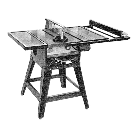
CRRFTSHRHo
12-INCH
MOTORIZED
TABLE SAW
• assembly
• operating
= repair parts
Sold
by SEARS,
ROEBUCK
AND
CO.,
Chicago,
IL
60684
U_S.A.
Part No. 62597
L_ ;_,,,:
Advertisement
Table of Contents

Related Manuals for Craftsman 113.24181


Summary of Contents for Craftsman 113.24181
- Page 1 MODEL NO. 113.24181 Serial Number Model and serial number may be found at the rear of the base. You should record both model and serial number in a safe place for futu re use. CAUTION-. Read GENERAL ADDITIONAL...
- Page 2 ON CRAFTSMAN this Craftsman Table Sae fails due to a defect by simply contacting the nearest Sears store or Service Center throughout and you also have other 13.
- Page 3 SEE PAGE 17 ADJUSTMENTS... SEE PAGE 23 MAINTENANCE... SEE PAGE 26 STABI LITY OF SAW If there is any tendency for the saw to tip over or move during certain cutting operations extremely large heavy panels or long heavy boards, the saw should be bolted down.
- Page 4 For greatest safety and efficiency when ripping, use the maximum diameter blade for which the saw is designed, since under these conditions the spreader is nearest the blade. 15, Adjust table inserts flush with the table top. NEVER operate the saw unlessthe proper insert is installed.
- Page 5 If power cord is worn or cut, or damaged it replaced immediately. CAUTION: This saw is wired for operation only. Connect to a 15 ampere branch circuit protected ampere time delay or circuit saver fuse breaker, WARNING:...
- Page 6 TOOLS NEEDED P, iers :iii! ?ii: iii iiii:!iii i;l Combination Square Model 113.24181 Motorized Table Saw isshipped complete in one carton including Two Table Extensions and Steel Legs. Separate all parts from packing materials and check each one with the illustration and the list of Loose Parts to make certain all items are accounted for, before discarding any packing material.
- Page 7 Install Iockwashers and nuts. DO NOT TIGHTEN. After all screws, washers and nuts are installed, all nuts. Install leveling feet. Place saw in upright position. Before proceeding with the assembly, Blade Squareness must be checked at this time. CHECKING TABLE INSERT 2.
- Page 8 18 (approx. dia. of hole 5/16 in.) Insert screws through holes in EXTENSION table. Install Iockwashers and screw on the nuts . .. NOT TIGHTEN. Align front edge of extension with front edge of saw table. Pull Extension UPWARDS above table surface...
- Page 9 2 Spacers, 3/4 in. dia. x 1/2 in. long 2 Self-threading nuts Lay guide bars on table. NOTE: The various holes in the bars allow repositioned on the saw and also makes them to other models, Insert 1 1/2 in. long screw through...
- Page 10 9. Holdrodwithone hand andwitha pliers start screwing on ONE of the nuts only ATURN OR TWO ... screw on other nut the same way. 10. Using TWO 7/16 in. wrenches or pliers tighten both of the nuts. 11. Slide the bars so that screws are in the MIDDLE of the slotted holes.
- Page 11 For very close adjustments, grasp the guide bar with hands and move the fence with your thumbs. Place fence on saw but DO NOT LOCK Move the REAR END of the fence slightly left when...
- Page 12 If the fence does not slide easily along the bars, the pressure of the spring can be REDUCED. 1. Loosen the screws. 2. Move spring slightly toward rear of fence screw_ rip fence must be PARALLEL Miter Gauge grooves Move along side of groove.
- Page 13 The folded paper will be used as a "spacing gauge". Place RIP FENCE on table CAREFULLY against blade so that it is parallel to the blade, and just TOUCHES tips of saw teeth . .. LOCK KNOB. Lift up both ANTI-KICKBACK PAWLS... of the SETSCREW WRENCHES in the notches the pawls out of the way.
- Page 14 POSSIBLE HAZARDOUS OTHERS. B. TO turn saw ON . .. stand to either side of the blade never in line with it ... switch lever and pull END of lever out. After turning switch ON, always allow the blade to come up to full speed before cutting.
- Page 15 YOUR SAFETY, TURN "OFF" REMOVE PLUG FROM SOURCE OUTLET BEFORE REMOVING front end, and pull toward OPERATE WITHOUT IN PLACE. USE THE SAW BLADE WHEN SAWING . . . DADO MOLDING INSERT OR MOLDING. cuts Make WHEN...
- Page 16 ARBOR WRENCH table, PULL ARBOR nut. ARBOR wrench PUSH ARBOR make sure the of the saw ... are clean, and free must be against TEETH POI NTING FRONT BLADE of the cut (kerf) line up mark on PULL TO LOOSEN...
-
Page 17: Basic Saw Operation Using
BASIC SAW OPERATION CROSSCUTTING, MITER CUTTING, COMPOUND MITER CUTTING and when RABBETING across the end of a narrow workpiece, THE GAUGE IS USED. WARNING: YOUR OBSERVE THE FOLLOWING SAFETY iN ADDITION TO THE SAFETY iNSTRUCTIONS PAGES 2, 3, and 4. - Page 18 CROSSCUTTING CROSSCUTTING is known cutting the grain, at 90 ° , or square with both side of the wood. This is done with miter graduations on the miter gauge average woodworking. some cases accuracy is required, when making angle cuts, for example, make a trial and then...
- Page 19 1. NEVER USE THERIPFENCE A SA LENGTH S TOP BECAUSE THE CUTOFF PIECECOULDBIND BETWEEN THEFENCE A ND THEBLADE CAUSING A KICKBACK. 2. When m aking r epetitive c uts shorter than 6 in.,clamp a block of wood 3 in. long to thetable toactasalength stop.
-
Page 20: Rip Fence
Frequently check the action of the ANTI-KICKBACK PAWLS by passing the workpiece alongside of the spreader while saw is OFF. Pull the workpiece TOWARD you. If the PAWLS do RIPPING RIPPING is known... -
Page 21: Rip Fence
When "WIDTH RIP" is 2 in. to 6 in. wide PUSH STICK to feed the work. When WIDTH OF RIP is NARROWER stick CANNOT be used because the guard will interfere AUXILIARY FENCE/WORK PUSH BLOCK. Attach auxiliary fence to rip fence with Feed the workpiece by hand until the end is approx. -
Page 22: Shown
RESAWING RESAWING is known as ripping a piece of wood its thickness. NOTE: RESAW a piece of wood than 3-9/16 in... it will be necessary guard AUXILIARY SUPPORT. (See "Work Helpers"). Do not attempt to resaw BOWED or WARPED material. Clamp it to the table so that the workpiece will SLIDE EASILY but not TILT... -
Page 23: Miter Gauge
WARNING: FOR YOUR OWN SAFETY, TURN SWITCH "OFF" REMOVE PLUG FROM POWER SOURCE OUTLET BEFORE MAKING ANY ADJUSTMENTS• MITER GAUGE NOTE: The holes for the stop pin and the graduations are manu-_actured to very close tolerances which provide accuracy for average woodworking• In some cases where extreme accuracy is required, when making angle cuts, for example, make a trial cut and then recheck it. -
Page 24: Blade To Table
8. Grasp spreader bar at rear of saw and move sideways •.. recheck blade alignment with square. 9. When blade is PARALLEL to groove.., "C'" and "'D". 10. Lay saw on its LEFT SIDE and tighten screws "'A" and SnB01" BLADE TILT, OR SQUARENESS OF BLADE TO TABLE 90 °... - Page 25 If blade ISSQUARE totable; A. Check p ointer If POINTER D OES NOTpointto the"0" markonthe bevel scale; B. Loosen screw andadjust pointer ... using m edium screwdriver. If blade isNOT SQUARE t otable..,the90 ° stop screw must b eADJUSTED. 1. Unscrew g 0 ° STOP SCREW three or fourturns using 3/16in.setscrew wrench.
-
Page 26: Maintenance
Do not allow sawdust to accumulate inside the saw. Frequently blow out any dust that may accumulate inside the saw cabinet and the motor. Frequently clean your cutting tools with Craftsman Gum and Pitch Remover. A coat of automobile-type wax applied to the table will help to keep the surface clean and allow workpieces to slide more freely. -
Page 27: Lubrication
Lay the saw on its LEFT SIDE. Clean following parts with Pitch Remover; BEVEL GEARS, TEETH, TILT WORM Lubricate these parts and other bearing with SAE No. 20 or No. 30 engine oil. -
Page 28: Trouble Shooting
TURN SWITCH "OFF" AND ALWAYS REMOVE PLUG FROM POWER SOURCE SHOOTING -- GENERAL PROBABLE CAUSE 1. Discard Blade and use a different blade. 2. See "Getting To Know Your Saw" to tighten section, "Tilt Lock Knob. 1. See "Adjustments" gauge not adjusted 1. -
Page 29: Breaker
1. Motor Motor overheats. 2. Improper cooling. (Air circulation restricted through motor due to sawdust, accumulating inside of saw). Starting relay in 1. Burned relay contacts motor will not (due to extended hold-in periods caused operate. by low line voltage, etc.) 2. - Page 30 Figure PARTS LIST FOR CRAFTSMAN 12-INCH MOTORIZED MODEL NUMBER 113.24181 TABLE SAW "0...
-
Page 31: Assembly
*Screw, Soc. Set 3/8-16 x 7/8 STD 541031 *Nut, Hex 5/16-18 STD 551231 *Lockwasher, 62539 Spacer, Fence Guide Bar PARTS LIST FOR CRAFTSMAN 12-INCH MODEL NUMBER 113.24181 Always order by Part Number - not by Key Number FIGURE 1 PARTS LIST... - Page 32 PARTS LIST FOR CRAFTSMAN 12-INCH MOTORIZED TABLE SAW MODEL NUMBER 113.24181 ..._ 66 _----_ 67 -'-" 69 Figure 2...
-
Page 33: Assembly
PARTS LiST FOR CRAFTSMAN 12-INCH MOTORIZED TABLE SAW Part Description 62459 Motor Assembly (See Fig. 4) 30494 Collar 60177 +Blade, Saw, 12" Chisel Tooth 6362 Nut, Saw Arbor 3540 Wrench, Arbor 63062 Wrench, Shaft STD 600803 *Screw, Self-Tapping, No. 8-32 x 3/8", Pan Hd. -
Page 34: Assembly
PARTS LIST FOR CRAFTSMAN FIGURE 62581 62524 STD 551031 62534 60049 62527 423350 62582 STD611005 62528 62529 62531 62583 62533 STD 551210 62532 STD 600805 Standard Hardware Item - May be Purchased Locally. 12-INCH MOTORIZED MODEL NUMBER 113.24181 3 - 62581 FENCE ASSEMBLY... -
Page 35: Available
Item -- May be Purchased attempt to repair this motor repair is done by qualified Service Repair service is available at your 12-INCH MOTORIZED TABLE SAW 113.24181 TO SWITCH AVAILABLE AT YOUR MOTOR ASSEMBLY Description Motor Assembly Control (w/Nameplate) Self-Tapping, No.6-32... -
Page 36: Assembly
PARTS LiST FOR CRAFTSMAN 9 --------_ _-J"_--'--" 8 SEE WIRING DIAGRAM, PAGE 5 FIGURE 5 -- SWITCH ASSEMBLY Part Description 62466 Bracket, Housing STD 601103 Screw, Type 23, 10-32 x 3/8", Pan Hd. STD 551210i Lockwasher, External No. 10 STD 541110 Nut, Hex., 10-32 x 3/8x... -
Page 37: Assembly
PARTS LIST FOR CRAFTSMAN MODEL NUMBER FIGURE 6- 62325 MITER GAUGE ASSEMBLY Part 62325 tGauge Assembly, Miter 62524 STD 551031 *Washer, Plain, 21/64 x 1 x 1/16" 37893 *Screw, Pan Hd. 8-32 x 5/16" STD 600803 37895 37896 *Screw, Pan Hd., w/Lockwasher,... -
Page 38: Assembly
PARTS LIST FOR CRAFTSMAN MODEL NUMBER FIGURE 7 -- 62594 GUARD Part 62594 60297 62391 62395 62389 62390 STD 551025 *Washer, 17/64 x 5/8 x 1/16" 62136 62396 62595 62410 STD 571810 *Pin, Roll, 3/16 x 15/16" 62134 * Standard Hardware Item - May Be Purchased Locally. -
Page 39: Assembly
PARTS LIST FOR CRAFTSMAN MODEL NUMBER FIGURE 8 -- 62589 TABLE EXTENSION Part 62589 Extension Assembly, Complete 60323 Screw, Serrated Truss Hd., 1/4-20 x 1" Extension 62590 62549 Bracket, Corner Support No. 2 62548 Bracket, Corner Support No. 1 STD 541025... -
Page 40: Repair Parts
Sears Service Center and most Sears, Roebuck Be sure to provide all pertinent The model number of your 12-inch table saw will be found plate attached to your saw, at the rear of the base. WHEN...