Table of Contents
Advertisement
f
Save This Manual
For Future Reference
S£ARS
owner's
manual
Model No.
113,244580
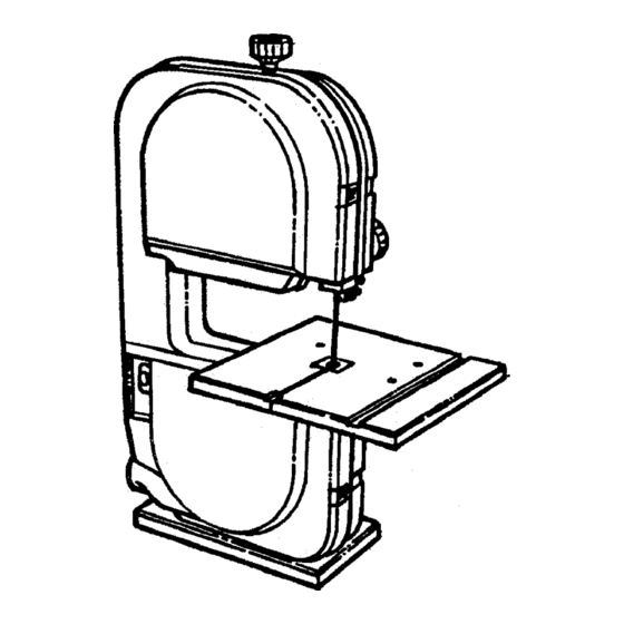
Two Wheel
9 Inch Band Saw
Serial
Number
Model and serial numbers
may be found at the rear of
the base.
You
should
record
both
model and serial number in
a safe place for future use.
FOR YOUR
SAFETY
SE/ Uq S/CRAFTSMAN
TWO WHEEL
9 INCH BAND SAW
• assembly
• operating
• repair parts
READ ALL
INSTRUCTIONS
CAREFULLY
Sears, Roebuck
and Co., Hoffman
Estates,
IL. 60179 U.S.A.
Part No. SP5872
J
Printed in Taiwan
Advertisement
Table of Contents

Related Manuals for Craftsman 113.244580


Summary of Contents for Craftsman 113.244580
- Page 1 Save This Manual For Future Reference S£ARS owner's manual Model No. 113,244580 Two Wheel 9 Inch Band Saw SE/ Uq S/CRAFTSMAN Serial Number Model and serial numbers may be found at the rear of TWO WHEEL the base. should record...
-
Page 2: Safety Instructions For Band Saw
FULL ONE YEAR WARRANTY ON CRAFTSMAN BAND SAW If within one year from the date of purchase, this Craftsman Band Saw fails due to a defect in material or workmanship, Sears will repair it, free of charge. WARRANTY SERVICE IS AVAILABLE... -
Page 3: Plan Your Work
To avoid injury from jams, slips, thrown pieces or ; Do not wear loose clothing, gloves, neckties or jewelry broken blades. (rings, wrist watches). They can get caught and draw Inspect your blade. you into moving parts. • Choose the right blade size, style and cutting speed for •... -
Page 4: Whenever Sawblade Is Moving
Safety Instructions for Band Saws (continued) Whenever Sawblade Is Moving: • Wait for all moving parts to stop. • Remove switch key. WARNING: Don't let familiarity (gained from fre- When backing up the workpiece, the blade may bind quent use of your band saw) cause a careless mis- in the kerr (cut). -
Page 5: Motor Specifications And Electrical Requirements
Motor Specifications and Electrical Requirements Power Supply and Motor Specifications It is recommended that you have a qualified electrician replace the Two prong outlet with a properly grounded The A-C motor used in this saw is non-reversibletype, hav- Three prong outlet. ing the followingspecifications: Grounding Lug Maximum Developed H.P. -
Page 6: Table Of Contents
Motor Specifications and Electrical Requirements (continued) 5. Motor troubles may be traced to loose or incorrect con- heating and motor burn-out, use the table below to deter- nections, overload, reduced input voltage (such as mine the minimum wire size (A.WG.) extension cord. -
Page 7: Unpacking And Checking Contents
Unpacking and Checking Contents Tools Needed Tools required for assembly and alignment: • #2 Phillips screwdriver • Adjustable wrench. • Combination Square Combination Square Must be True Straight Edge of Draw Light Board 3/4" Thick #2 Phillips Screwdriver Line on Board This Edge Must be 6"... -
Page 8: List Of Loose Parts
Unpacking and Checking Contents (continued) List of Loose Parts NOTE: Before beginning assembly, check that all parts are included. If you are missing any part, do not assem- ble the saw. Contact your Sears Service Center to get the missing part. Sometimes small parts can get lost in pack- aging material. -
Page 9: Assembly
Assembly WARNING: For your own safety, never connect plug to power source outlet until all assembly steps are complete, and you have read and under- stood the safety and operational instructions. From the loose parts find the following items: Item No. Description 1/4-20 x 7/8"... -
Page 10: Installing The Blade
Assembly (continued) Installing the Blade and l I WARNING: unplug saw before removing or installing blade. Turn off saw, remove switch key 1. Open front cover by pushing in upper and lower latches. 2. Loosen the upper slide lock knob and position the blade guard/guide assembly about half way between the table and the frame. -
Page 11: Alignment (Adjustments)
Alignment (Adjustments) Tension Adjusting Knob Tensioning the Blade be permanently damaged. Wear your safety gog- I WARNING: Cut material can be thrown. Eyes can gles. I WARNING: Turn off saw, remove switch key and unplug before adjusting. 1. Turn blade tension adjusting knob clockwise until the proper section of knob stern is aligned with top of band saw frame. -
Page 12: Adjusting Upper Blade Guard Assembly
Alignment (Adjustments) (continued) Adjusting Upper Blade Guard Assembly Upper Slide The upper blade guard assembly should always be set Lock Knob about 1/8" above or as close as possible to the top sur- face of the workpiece being cut. 1. Loosen the upper slide lock knob. Upper Guard Assembly 2. -
Page 13: Adjusting The Blade Guides And Back-Up Bearing
Adjusting the Blade Guides and Back-Up Bearing Upper I WARNING: Turn off saw, remove switch key and I unplug before making any adjustments. Bearing NOTE: The upper and lower blade guides and back-up Cap Screw bearings support the band saw blade during cutting oper- ations. -
Page 14: Adjusting Motor Belt Tension
Alignment (Adjustments) (continued) 2. If adjustment is necessary, loosen the upper motor Adjusting Motor Belt Tension bolt and lower motor pivot bolt. Move the motor to cor- WARNING: Turn off saw, remove switch key and I rect the belt tension. Retighten both motor bolts. unplug before making any adjustments. -
Page 15: Clamping Band Saw To Workbench
Clamping Band Saw to Workbench The band saw can be clamped directly to a workbench using two (2) or more "C" clamps on base of unit. Mounting Band Saw to Accessory Legset Cat. No. 9-22244 Oaoa ,,,d Attach to holes indicated by "m" Legset Mounting Holes... -
Page 16: Getting To Know Your Band Saw
Getting to Know Your Band Saw 1. Blade Guides - Supports the blade and keeps it from 7. Tracking Adjustment Set Screw - Adjust to Keep twisting during operation. An adjustment is necessary blade running in center of wheels. when blades are changed or replaced. 8. - Page 17 13. On-Off Switch - The On-Off switch has a locking fea- ture. This feature is intended to help prevent unautho- rized and possible hazardous use by children and others. 1. To turn band saw "On" insert key into switch. NOTE: Key is made of yellow plastic, located in loose parts bag.
-
Page 18: Safety Instructions For Basic Band Saw Operation
Safety Instructions for Basic Band Saw Operation Before Using the Saw: • Remove adjusting keys and wrenches. Form a habit of checking for removing keys and adjusting WARNING: to avoid mistakes that could cause seri- wrenches from table top before turning it on. ous, permanent injury, do not plug the saw in until To avoid injury from jams, slips or thrown pieces or the following steps have been completed. -
Page 19: Dress For Safety
Safety Instructions for Basic Band Saw Operation (continued) Dress For Safety Plan the Way You Will Hold the Workpiece From Start To Finish. • Any power saw can throw foreign objects into the eyes. This can cause permanent eye damage. Wear safety •... -
Page 20: Basic Band Saw Operations
Basic Band Saw Operations General Cutting safety instructions in "Safety Instructions for Band I CAUTION: For your safety, comply with all the l Saw" section before using the band saw. A band saw is a "curve cutting" machine. It is also used for straight-line cutting operations such as crosscutting, ripping, mitering, beveling, compound cut- ting and resawing. -
Page 21: Maintenance
Maintenance Do not allow filth to build up on the table the guides or the back-up bearings. Clean them with Craftsman Gum and Pitch Remover. I DANGER: Never put lubricants on the blade while it I is spinning. -
Page 22: Troubleshooting
Troubleshooting WARNING: For your own safety, turn switch "Off" and remove plug from power source outlet before trouble shooting your band saw/sander. General Trouble Probable Cause Remedy Blade does not run in the 1. Not tracking properly. 1. Adjust tracking, see Alignment section, "Tracking the approximate center of the Blade". -
Page 23: Motor
Motor NOTE: Motors used on wood-working tools are particularly susceptible to the accumulation of sawdust and wood chips and should be blown out or "vacuumed" frequently to prevent interference with normal motor ventilation and proper operation of the centrifugally-operated starting switch. Trouble Probable Cause Remedy... -
Page 24: Repair Parts
Parts List For Craftsman 9-inch Band Saw Model No. 113.244580 Figure I 9 10 I /l_J I t_tt 9 1011... -
Page 25: Parts List
Parts List For Craftsman 9 Inch Band Saw Model No. 113.244580 Always Order By Part Number- Not By Key Number Figure I - Drive Assembly Parts Part No. Description Part No. Description Knob Tension 824064 Block Guide 824042 * Washer 21/64 x 47/64 x 1/16... - Page 26 Notes...
- Page 27 Notes...
- Page 28 SEARS owner's TWO WHEEL manual 9 INCH BAND SAW Model No. 113.244580 For the repair or replacement parts you need Two Wheel Call 7 am - 7 pro, 7 days a week 1-800-366-PART 9 Inch Band Saw (1-800-366-7278) For in-home major brand repair service Call 24 hours a day, 7 daysa week 1-8OO-4-REPAIR (1-800-473-7247)