Table of Contents
Advertisement
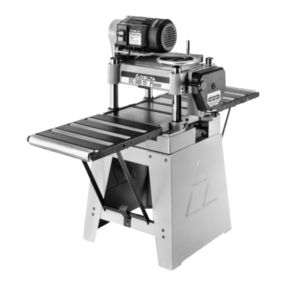
Shown with Delta
Model 50-654 Accessory
Planer Stand and
Roller Extension Tables
To learn more about DELTA MACHINERY
visit our website at: www.deltamachinery.com.
For Parts, Service, Warranty or other Assistance,
1-800-223-7278 (
please call
DC-380 15" Planer
(Model 22-680, Single Phase)
(Model 22-681, Three Phase)
1-800-463-3582).
In Canada call
PART NO. 1346996 - 07-30-04
Copyright © 2004 Delta Machinery
Advertisement
Table of Contents

Related Manuals for Delta 22-681


Summary of Contents for Delta 22-681
- Page 1 For Parts, Service, Warranty or other Assistance, 1-800-223-7278 ( please call DC-380 15" Planer (Model 22-680, Single Phase) (Model 22-681, Three Phase) 1-800-463-3582). In Canada call PART NO. 1346996 - 07-30-04 Copyright © 2004 Delta Machinery...
-
Page 2: Table Of Contents
IMPORTANT SAFETY INSTRUCTIONS ............2 SAFETY GUIDELINES . -
Page 3: Safety Guidelines
SAFETY GUIDELINES - DEFINITIONS It is important for you to read and understand this manual. The information it contains relates to protecting YOUR SAFETY and PREVENTING PROBLEMS. The symbols below are used to help you recognize this information. Indicates an imminently hazardous situation which, if not avoided, will result in death or serious injury. Indicates a potentially hazardous situation which, if not avoided, could result in death or serious injury. -
Page 4: General Safety Rules
READ AND UNDERSTAND ALL WARNINGS AND OPERATING INSTRUCTIONS BEFORE USING THIS EQUIPMENT. Failure to follow all instructions listed below, may result in electric shock, fire, and/or serious personal injury or property damage. 1. FOR YOUR OWN SAFETY, READ THE INSTRUCTION MANUAL BEFORE OPERATING THE MACHINE. -
Page 5: Additional Specific Safety Rules
ADDITIONAL SAFETY RULES FOR PLANERS FAILURE TO FOLLOW THESE RULES MAY RESULT IN SERIOUS PERSONAL INJURY DO NOT OPERATE THIS MACHINE until it is completely assembled and installed according to the instructions. A machine incorrectly assembled can cause serious injury. OBTAIN ADVICE from your supervisor, instructor, or another qualified person if you are not thoroughly familiar with the operation of this... -
Page 6: Grounding Instructions
MOTOR SPECIFICATIONS The motor supplied with your 15” Planer is either a three horsepower, single phase motor, or a three horsepower, three phase motor. The three horsepower, single phase motor is wired for 230 Volt operation and the three horsepower, three phase motor is wired for 200-220 Volt operation. -
Page 7: Functional Description
FUNCTIONAL DESCRIPTION FOREWORD Delta Model 22-680 is a 15" (381mm) Planer with adjustable feed rate for optimum planing under load. It has the following cutting capacities; 15" (381mm) width, 6½" (165mm) thickness and 1/8" (5mm) depth of cut. NOTICE: THE PHOTO ON THE MANUAL COVER ILLUSTRATES THE CURRENT PRODUCTION MODEL. -
Page 8: Carton Contents
Your new 15" Planer is shipped complete in one box (Fig. 2). IMPORTANT: Care must be taken when removing the machine from the container. The machine is very heavy and a minimum of four people will be required to lift the machine (see the section “LIFTING THE MACHINE”). -
Page 9: Assembly
(J). LIFTING THE MACHINE 1. IMPORTANT: CARE MUST BE TAKEN WHEN LIFTING THE MACHINE ONTO A STAND OR WORKBENCH. THE PLANER IS VERY HEAVY AND A MINIMUM OF FOUR PEOPLE WILL BE REQUIRED TO LIFT THE MACHINE AS FOLLOWS: 2. - Page 10 ASSEMBLING SWITCH TO PLANER (THREE PHASE MACHINE ONLY) The switch for the three phase 15² Planer is supplied wired to the motor and is to be fastened to the planer as follows: 1. Line up the two holes (A) Fig. 10A, in the switch bracket (C) with the two threaded holes (B) in the left front of the machine.
- Page 11 (C). The offset between the top shelf of the stand and the base of the planer will be on the left side. Mount the machine to the top shelf using the four 1" long hex head screws, flat washers, lock washers and hex nuts supplied.
-
Page 12: Operation
OVERLOAD PROTECTION (Three Phase Machine Only) The three phase machine is provided with overload protection which will shut off the motor if the planer is overloaded or if line voltage falls below safe levels. If the motor shuts off due to overloading or low voltage, let the motor cool for approximately five minutes. -
Page 13: Feed Speed Control
DEPTH OF CUT ADJUSTMENT The depth of cut on your planer is controlled by raising or lowering the head assembly (A) Fig. 22, which contains the cutterhead and feed rollers. The head assembly (A) moves on four precision ground steel columns, three of which are shown at (B). - Page 14 MACHINE IS DISCONNECTED FROM THE POWER SOURCE. A series of anti-kickback fingers (A) Fig. 27, are provided on the infeed end of the planer, to prevent kickback of the workpiece during the planing operation. These anti- kickback fingers operate by gravity and no adjustment is required.
- Page 15 CHECKING, ADJUSTING AND REPLACING KNIVES To check, adjust or replace the knives, proceed as follows: DISCONNECT MACHINE FROM POWER SOURCE. 1. Remove four screws (A) Fig. 30 and Fig. 31, and remove top cover (B). 2. Loosen two screws (C) Fig. 32, and pivot motor assembly (D) to the front.
- Page 16 Fig. 34 5. If the knives are removed for sharpening, care must be exercised in replacing and resetting them, as follows: A. Remove the knife (M) Fig. 37, locking bar (N), and locking screws (K) from the cutterhead. Repeat this process for the two remaining knives, locking bars, and locking screws.
- Page 17 ADJUSTING HEIGHT OF CHIPBREAKER The chipbreaker extends down around the front of the cutterhead and raises as stock is fed through the planer. The chipbreaker “breaks or curls” the chips as they leave the cutterhead and the bottom edge of the chipbreaker helps hold the stock flat down on the table during the planing operation.
- Page 18 ADJUSTING HEIGHT OF INFEED ROLLER The infeed roller is adjusted at the factory at 0.040" below the cutting circle. To check and adjust the height of the infeed roller, proceed as follows: DISCONNECT MACHINE FROM POWER SOURCE. 1. Make sure the knives are adjusted properly as explained under “CHECKING, ADJUSTING AND REPLACING KNIVES.”...
- Page 19 Your planer is supplied with two table rollers (A) Fig. 47, which aid in feeding the stock by reducing friction and turn as the stock is fed through the planer. It is not possible to give exact dimensions on the proper height setting of the table rollers because each type of wood behaves differently.
- Page 20 Repeat STEPS 2 and 3 on outfeed end of table. 4. If head casting is not parallel to table, tilt planer on its side as shown in Fig. 51. Remove bolt (C) and loosen bolt (D) Fig. 51, which will allow you to move the idler sprocket assembly (E) far enough to release tension on chain as shown in Fig.
-
Page 21: Troubleshooting
2. Plane to Thickness – Place the side you just surfaced in STEP 1 face down and feed the board through the planer, plane until this side is flat. Then plane both sides of the board until you are satisfied with the thickness, making thin cuts, alternating sides with each pass. -
Page 22: Maintenance
KEEP MACHINE CLEAN Periodically blow out all air passages with dry compressed air. All plastic parts should be cleaned with a soft damp cloth. NEVER use solvents to clean plastic parts. They could possibly dissolve or otherwise damage the material. Wear ANSI Z87.1 safety glasses while using compressed air. -
Page 23: Service
PARTS, SERVICE OR WARRANTY ASSISTANCE All Delta Machines and accessories are manufactured to high quality standards and are serviced by a network • of Porter-Cable Delta Factory Service Centers and Delta Authorized Service Stations. To obtain additional information regarding your Delta quality product or to obtain parts, service, warranty assistance, or the location of the nearest service outlet, please call 1-800-223-7278 (In Canada call 1-800-463-3582). - Page 24 PORTER-CABLE (CENTROS DE SERVICIO DE PORTER-CABLE Parts and Repair Service for Porter-Cable (Obtenga Refaccion de Partes o Servicio para su Herramienta en los Siguientes Centros de Porter-Cable ARIZONA Tampa 33609 Tempe 85282 (Phoenix) 4538 W. Kennedy Boulevard 2400 West Southern Avenue Phone: (813) 877-9585 Suite 105 Fax: (813) 289-7948...