Table of Contents
Advertisement
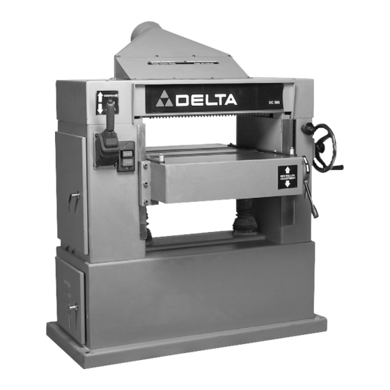
DC-580 20" Planer
(Model 22-450, Three Phase)
(Model 22-451, Single Phase)
PART NO. 1349960 - 06-02-05
Copyright © 2005 Delta Machinery
To learn more about DELTA MACHINERY
visit our website at: www.deltamachinery.com.
For Parts, Service, Warranty or other Assistance,
1-800-223-7278 (
1-800-463-3582).
please call
In Canada call
Advertisement
Table of Contents

Related Manuals for Delta DC-580 20" PLANER 22-450


Summary of Contents for Delta DC-580 20" PLANER 22-450
- Page 1 DC-580 20" Planer (Model 22-450, Three Phase) (Model 22-451, Single Phase) PART NO. 1349960 - 06-02-05 Copyright © 2005 Delta Machinery To learn more about DELTA MACHINERY visit our website at: www.deltamachinery.com. For Parts, Service, Warranty or other Assistance, 1-800-223-7278 ( 1-800-463-3582).
-
Page 2: Table Of Contents
NOT be modified and/or used for any application other than for which it was designed. If you have any questions relative to its application DO NOT use the product until you have written Delta Machinery and we have advised you. -
Page 3: Safety Guidelines
SAFETY GUIDELINES - DEFINITIONS It is important for you to read and understand this manual. The information it contains relates to protecting YOUR SAFETY and PREVENTING PROBLEMS. The symbols below are used to help you recognize this information. Indicates an imminently hazardous situation which, if not avoided, will result in death or serious injury. Indicates a potentially hazardous situation which, if not avoided, could result in death or serious injury. -
Page 4: General Safety Rules
GENERAL SAFETY RULES IMPORTANT SAFETY INSTRUCTIONS Delta may cause damage to the machine or injury to the user. 14. USE THE PROPER EXTENSION CORD. Make sure your extension cord is in good condition. When using an extension cord, be sure to use one heavy enough to PROTECTION. -
Page 5: Additional Specific Safety Rules
ADDITIONAL SPECIFIC SAFETY RULES FAILURE TO FOLLOW THESE RULES MAY RESULT IN SERIOUS INJURY. DO NOT OPERATE THIS MACHINE until it is completely assembled and installed according to the instructions. A machine incorrectly assembled can cause serious injury. OBTAIN ADVICE from your supervisor, instructor, or another qualified person if you are not thoroughly familiar with the operation of this machine. -
Page 6: Functional Description
FUNCTIONAL DESCRIPTION FOREWORD The Delta Indusrial Model 22-450 (DC-580) 20" Planer has a 3-phase, 5HP motor with an LVC magnetic starter and automatic reset overload protection; 3-knife cutterhead, sectional serrated infeed roll, double bed rollers and polyurethane outfeed roller, sectional chipbreakers, dust chute, knife-setting gage, and wrench. The Delta Industrial Model 22-451 (DC-580) 20"... -
Page 7: Carton Contents
The DC-580, 20" planer is shipped complete in one container mounted to a shipping skid. Remove the wooden crate from around the machine. The planer is shipped with the motor, motor pulleys and belts assembled to the machine. Fig. 2, illustrates the loose items supplied with the machine. - Page 8 NOTE: The other lifting lug is located at the rear and the opposite end of the machine. Carefully remove the planer from the shipping skid. Thread handle assembly (A) Fig. 3, into handwheel (B) and tighten locknut (C).
- Page 9 ASSEMBLING DUST HOOD A dust hood with a 5" opening is supplied with your machine and is to be used when connecting the planer to a dust collector or a central dust collection system. Position dust hood (A) Fig. 8, against the rear of the machine and on top of cutterhead guard (B).
-
Page 10: Electrical Connections
Remove plastic shield (D) Fig. 11, from terminal strip (E). THREE PHASE OPERATION If the planer is wired for three phase operation, connect the three power lines to terminals (F), (G) and (K) Fig. 12, and the green ground wire to ground terminal (H). -
Page 11: Operation
STARTING AND STOPPING THE PLANER 1. The power switch (A) Fig. 13 is located on the front of the planer. To turn the machine on, push the “START” button. 2. To turn the machine off, push the stop button (B). - Page 12 Fig. 16 FEED ROLLER SPEEDS Your planer is equipped with feed roller speeds of 20 and 30 feet per minute depending on belt placement on the pulleys. As a rule, a faster feed rate is used for general planing operations, while a slower feed rate (because it provides more cuts per inch of stock) gives a finer and smoother finish to the workpiece.
- Page 13 TABLE ROLLERS Your planer is supplied with two table rollers (A) Fig. 21, which aid in feeding the stock by reducing friction be- tween the stock and the table and rotate as the stock is fed through the planer. 1. To raise the table rollers, loosen locking lever (B) Fig.
- Page 14 ANTI-KICKBACK FINGERS A series of anti-kickback fingers (A) Fig. 27, are provided on the infeed end of the planer to prevent kickback of the workpiece during planing operations. These anti-kickback fingers operate by gravity and no adjustment is required. It...
- Page 15 CHECKING AND ADJUSTING DRIVE BELT TENSION Proper belt tension is when there is approximately 1/4" deflection, using light finger pressure on the drive belts (A) Fig. 28, midway between pulleys. If an adjustment is necessary, proceed as follows: Fig. 28 DISCONNECT MACHINE FROM POWER SOURCE.
- Page 16 CHECKING AND ADJUSTING FEED ROLLER BELT TENSION Proper tension on the feed roller belt is obtained when there is approximately 1/2" deflection, using light finger pressure on feed roller belt (A) Fig. 30. midway between pulleys (B) and (C), with feed roller lever (D) engaged. If an adjustment is necessary, proceed as follows: DISCONNECT MACHINE FROM POWER SOURCE.
- Page 17 CHECKING, RESETTING AND REPLACING KNIVES When checking, resetting and replacing knives, proceed as follows: DISCONNECT MACHINE FROM POWER SOURCE. 2. Remove locking screw (E) Fig. 4, and raise top cover (A) Fig. 33, to expose cutterhead (B). 3. Carefully place knife setting gage (C) Figs. 34 and 35, so the gage is positioned on the radiused section of cutterhead (B).
- Page 18 The chipbreakers will rise as stock is fed through the planer and “breaks or curls” the wood chips. The bottom of the chipbreakers must be parallel to the knives and set .040" below the cutting circle. To check and...
- Page 19 ADJUSTING PRESSURE BAR The pressure bar is located directly behind the cutterhead and rides on the planed surface of the stock, pressing the stock downward on the table. The pressure bar must be parallel to the knives and tangent to the table and set .010" below the cutting circle.
- Page 20 7. Tighten locknuts (E) Fig. 45 after adjustments are com- pleted. ADJUSTING INFEED ROLLER The infeed roller feeds the stock into the planer while the stock is being surfaced. The infeed roller must be positioned uniformly across the planer and .040" below the cutting circle to feed the stock without slipping.
- Page 21 The table height scale indicates the distance the table is from the cutting circle (depth of cut). To check and adjust the pointer, proceed as follows: 1. Run a piece of wood through the planer and stop the machine. 2. Measure the thickness of the planed end of the stock as shown in Fig.
-
Page 22: Troubleshooting
2. Plane to Thickness – Place the side you planed in STEP 1 face down and feed the board through the planer. Plane until this side is flat, then plane both sides of the board until you are satisfied with the thickness. Make thin cuts, and alternate sides with each pass. -
Page 23: Service
Two Year Limited New Product Warranty Delta will repair or replace, at its expense and at its option, any new Delta machine, machine part, or machine accessory which in normal use has proven to be defective in workmanship or material, provided that the customer returns the product prepaid to a Delta factory service center or authorized service station with proof of purchase of the product within two years and provides Delta with reasonable opportunity to verify the alleged defect by inspection. - Page 24 Phone: (604) 420-0102 Fax: (604) 420-3522 The following are trademarks of PORTER-CABLE • DELTA (Las siguientes son marcas registradas de PORTER-CABLE • DELTA S.A.) (Les marques suivantes sont des marques de fabriquant de la PORTER-CABLE • DELTA): Auto-Set Contractor’s Saw II™, Delta ®...