Table of Contents
Advertisement
²
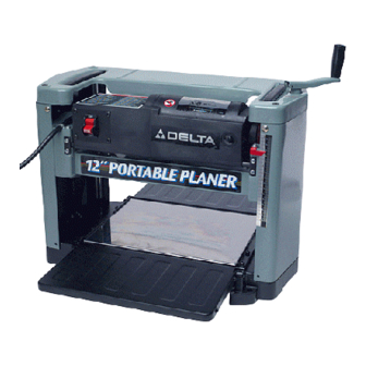
12
Portable Planer
(Model 22-540)
PART NO. 901606 (013)
Copyright © 2001 Delta Machinery
To learn more about DELTA MACHINERY
ESPAÑOL: PÁGINA 17
visit our website at: www.deltamachinery.com.
For Parts, Service, Warranty or other Assistance,
1-800-223-7278 (
1-800-463-3582).
please call
In Canada call
Advertisement
Table of Contents

Related Manuals for Delta 22-540


Summary of Contents for Delta 22-540
- Page 1 ² Portable Planer (Model 22-540) PART NO. 901606 (013) Copyright © 2001 Delta Machinery To learn more about DELTA MACHINERY ESPAÑOL: PÁGINA 17 visit our website at: www.deltamachinery.com. For Parts, Service, Warranty or other Assistance, 1-800-223-7278 ( 1-800-463-3582). please call...
-
Page 2: Safety Rules
If you have any questions relative to a particular application, DO NOT use the machine until you have first contacted Delta to determine if it can or should be performed on the product. - Page 3 4. MAKE all adjustments with the power off. 5. DISCONNECT machine from power source when making repairs. 6. NEVER turn the planer “ON” before clearing the table of all objects (tools, scraps of wood, etc.). 7. KEEP knives sharp and free of all rust and pitch.
-
Page 4: Grounding Instructions
CONNECTING TOOL TO POWER SOURCE A separate electrical circuit should be used for your tools. This circuit should not be less than #12 wire and should be protected with a 20 Amp time lag fuse. If an extension cord is used, use only 3-wire extension cords which have 3- prong grounding type plugs and 3-hole receptacles which accept the tool’s plug. -
Page 5: Extension Cords
FOREWORD Delta Model 22-540 is a 12" (305mm) Portable Planer with adjustable feed rate for optimum planing under load. It has the following cutting capacity; 12" (305mm) width , 6" (152mm) thickness and 3/16" (5mm) depth of cut. Features include;... -
Page 6: Unpacking And Cleaning
After cleaning, cover the unpainted sufaces with a good quality paste wax. CAUTION: CARE MUST BE TAKEN WHEN CLEANING THE CUTTERHEAD AS THE KNIVES ARE SHIPPED IN THE CUTTERHEAD AND THEY ARE VERY SHARP. Figs. 2 and 3, ILLUSTRATE THE PLANER AND ALL LOOSE ITEMS SUPPLIED WITH THE MACHINE. -
Page 7: Assembly Instructions
The infeed and outfeed extension tables (A) Fig. 6, are shipped attached to the machine in the raised position. Lower the tables (A) on both sides of the planer as shown in Fig. 6. The top surface of extension tables should be level with the planer table. - Page 8 ASSEMBLING CHIP DEFLECTOR 1. Assemble chip deflector (A) Fig. 7, to the planer by inserting end of chip deflector over the top of the cutterhead. Make certain the two screws, one of which is shown at (B) are inserted upward through the two slots (C) in the chip deflector.
-
Page 9: Operating Controls And Adjustments
(B). NOTE: One revolution of the handle will move the cutterhead up or down approximately 5/64 . An English/metric scale (C) and pointer (D) is located on the side of the planer for ease in setting the height of the cutterhead. RECOMMENDED... -
Page 10: Leveling Extension Tables
(A) with one end extending out over the extension table as shown. Check to see if the infeed table is level with the planer table on both ends of the extension table. 2. If an adjustment is necessary, loosen locknut (C) Fig. -
Page 11: Replacing And Resetting Knives
Fig. 21 Fig. 22 5. If an adjustment to one or both knives is necessary, slightly loosen the seven locking screws, six of which are shown at (C) Fig. 21, by turning the screws CLOCKWISE into the knife locking bar just enough to relieve stress in the cutterhead and not disturb the knife setting. -
Page 12: Lifting Straps
3. Plane to Thickness – Place the side you just surfaced in STEP 2 face down and feed the board through the Planer, as shown in Figs. 24 and 25. Plane both sides of the board until you are satisfied with the thickness, making thin cuts with each pass. -
Page 13: Maintenance
(C) Fig. 29, and a light coat of spray lubricant to chains (F). Replace the side cover. 4. Lay the planer on its back and squirt oil on the feed roller bushings (D) Fig. 30, at each end of the feed rolls (E). - Page 14 Delta Building Trades and Home Shop Machinery Delta will repair or replace, at its expense and at its option, any Delta machine, machine part, or machine accessory which in normal use has proven to be defective in workmanship or material, provided that the customer returns the product prepaid to a Delta factory service center or authorized service station with proof of purchase of the product within two years and provides Delta with reasonable opportunity to verify the alleged defect by inspection.
- Page 15 NOTES...
- Page 16 NOTES...
- Page 17 Parts and accessories for Porter-Cable Delta products should be obtained by contacting any Porter-Cable Delta Distributor, Authorized Service Center, or Porter-Cable Delta Factory Service Center. If you do not have access to any of these, call 888-848-5175 and you will be directed to the nearest Porter-Cable Delta Factory Service Center. Las Estaciones de Servicio Autorizadas están ubicadas en muchas grandes ciudades.