Advertisement
12½" Portable Planer
(Model 22-560, 22-565 W/Stand)
Model 22-565 W/Stand
PART NO. 903361 (016)
Copyright © 2001 Delta Machinery
To learn more about DELTA MACHINERY
ESPAÑOL: PÁGINA 19
visit our website at: www.deltamachinery.com.
For Parts, Service, Warranty or other Assistance,
1-800-223-7278 (
1-800-463-3582).
please call
In Canada call
Advertisement
Table of Contents

Related Manuals for Delta 22-560


Summary of Contents for Delta 22-560
- Page 1 12½" Portable Planer (Model 22-560, 22-565 W/Stand) Model 22-565 W/Stand PART NO. 903361 (016) Copyright © 2001 Delta Machinery To learn more about DELTA MACHINERY ESPAÑOL: PÁGINA 19 visit our website at: www.deltamachinery.com. For Parts, Service, Warranty or other Assistance, 1-800-223-7278 ( 1-800-463-3582).
-
Page 2: General Safety Rules
If you have any questions relative to a particular application, DO NOT use the machine until you have first contacted Delta to determine if it can or should be performed on the product. - Page 3 ADDITIONAL SAFETY RULES FOR PLANERS 1. DO NOT operate your tool until it is completely 16. MAKE SURE the workpiece is free from nails and assembled and installed according to the instructions. other foreign objects which could cause injury or damage to the blades.
-
Page 4: Unpacking And Cleaning
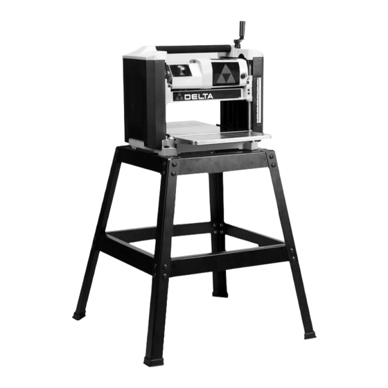
FOREWORD Delta Model 22-560 is a 12½" (317mm) Portable Planer. It has the following cutting capacity; 12½" (317mm) width, 6" (152mm) thickness and 3/32" (3mm) maximum depth of cut. Features include; basic machine with powerful 15 amp, 120 volt motor, dust chute, two-knife cutterhead with double-edged reversible knives, knife-installation tool, and wrench. - Page 5 ASSEMBLY Stand Assembly For Model 22-565 A - Top Brace 17-7/8" (4) B - Bottom brace 22-1/4" (4) C - Leg (4) D - Rubber feet (4) E - Carriage bolt M8 x 1.25 x 16 (32) F - Flange nut M8 x 1.25 (36) * - Hex head flange screw M8 x 1.25 x 35 (4) (For fastening planer to stand) * not shown 1.
- Page 6 ASSEMBLING CUTTERHEAD RAISING AND LOWERING HANDLE 1. Assemble the cutterhead raising and lowering handle (A) Fig. 7, to shaft (B), making certain flat on shaft is engaged with flat in handle. Fig. 7 2. Fasten cutterhead raising and lowering handle (A) Fig.
-
Page 7: Grounding Instructions
CONNECTING TOOL TO POWER SOURCE POWER CONNECTIONS A separate electrical circuit should be used for your tools. This circuit should not be less than #12 wire and should be protected with a 20 Amp time lag fuse. If an extension cord is used, use only 3-wire extension cords which have 3- prong grounding type plugs and 3-hole receptacles which accept the tool’s plug. -
Page 8: Operating Controls And Adjustments
EXTENSION CORDS MINIMUM GAUGE EXTENSION CORD RECOMMENDED SIZES FOR USE WITH STATIONARY ELECTRIC TOOLS Use proper extension cords. Make sure your extension Ampere Total Length Gauge of Rating Volts of Cord in Feet Extension Cord cord is in good condition and is a 3-wire extension cord which has a 3-prong grounding type plug and a 3-hole up to 25 18 AWG... - Page 9 SCALE AND POINTER A dual English/Metric scale (D) Fig. 17, and pointer (E) is conveniently located on the front of the machine and in- dicates the thickness of the finished workpiece. Adjust- ment to the pointer can be made by running a piece of wood through the machine.
-
Page 10: Cord Storage
KNIFE TRANSFER TOOL STORAGE 1. The knife transfer tool (A) Fig. 20, supplied with your planer, can easily be stored underneath the outfeed table extension (B) when not being used. A Velcro strip (C) is provided on the tool and underneath the table for this purpose. -
Page 11: Replacing Knives
Fig. 25 Fig. 26 CARRYING HANDLE/STOCK TRANSFER BAR 1. Your planer is provided with a foam covered carrying handle (A) Fig. 25, located on top of the machine, for ease in transporting the planer. Carrying handles are also provided at the base of the planer on each side which allow you to lift the machine with ease. - Page 12 6. Figure 29 illustrates the cutterhead (C) locked in place allowing access to the knife locking bar (E). Fig. 29 7. Using the wrench (E) Fig. 30, supplied, unscrew the six screws, five of which are shown at (F), only enough until locking bar (D) separates from knife, allowing knife to be removed.
- Page 13 10. Remove knife transfer tool and tighten the six screws, five of which are shown at (F) Fig. 33, using wrench (E) supplied. 11. Replace other knife by rotating head 180 degrees and repeat STEPS 5 THROUGH 10. Fig. 33 12.
- Page 14 3. Make sure the knives are inserted into the cutterhead properly, as explained under “REPLACING KNIVES.” 4. Place the gage block (A) Fig. 37, on the table, over a 0.020" feeler gage and position the gage block (A) directly underneath the cutterhead. Raise or lower the head assembly and rotate the cutterhead, by following STEP 5 under “REPLACING KNIVES,”...
-
Page 15: Maintenance
MAINTENANCE BRUSH INSPECTION AND REPLACEMENT DISCONNECT TOOL FROM POWER SOURCE. Brush life varies. It depends on the load on the motor. Check the brushes after the first 50 hours of use for a new machine or after a new set of brushes has been installed. - Page 16 Two Year Limited Warranty Delta will repair or replace, at its expense and at its option, any Delta machine, machine part, or machine accessory which in normal use has proven to be defective in workmanship or material, provided that the customer returns the product prepaid to a Delta factory service center or authorized service station with proof of purchase of the product within two years and provides Delta with reasonable opportunity to verify the alleged defect by inspection.