Hanna Instruments HI 720 Instruction Manual
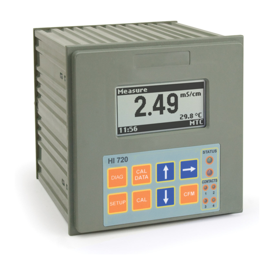
Conductivity process controller with inductive probe
Hide thumbs
Also See for HI 720:
- Instruction manual (84 pages) ,
- Manual (2 pages) ,
- Instruction manual (2 pages)

Related Manuals for Hanna Instruments HI 720


Summary of Contents for Hanna Instruments HI 720
- Page 1 Instruction Manual HI 720 Conductivity Process Controller with Inductive Probe w w w . h a n n a i n s t . c o m...
-
Page 2: Table Of Contents
TABLE OF CONTENTS WARRANTY .....................4 PRELIMINARY EXAMINATION ................5 MODEL IDENTIFICATION ..................5 GENERAL DESCRIPTION & THEORY OF OPERATION .......... 6 SPECIFICATIONS ....................9 FUNCTIONAL DESCRIPTION ................10 INSTALLATION ....................12 OPERATIONAL GUIDE ..................14 • SETUP MODE ..................14 • CALIBRATION MODE ................34 •... -
Page 3: Warranty
If the repair is not covered by the warranty, you will be notified of the charges incurred. If the instrument is to be returned to Hanna Instruments, first obtain a Returned Goods Authorization number from the Customer Service department and then send it with shipping costs prepaid. -
Page 4: General Description & Theory Of Operation
For an inductive cell, the cell constant is defined as the measured conductivity, GENERAL DESCRIPTION & THEORY OF OPERATION obtained by making a loop through the sensor with a resistor R, multiplied by This instrument allows conductivity measurements without any electrical contact that R value. -
Page 5: Specifications
The main features of the HI 720 controller series include: SPECIFICATIONS • Measurement and control of conductivity or concentration • Concentration can be measured as usual TDS (fixed ratio) or through custom conductivity/temperature/concentration curves Range 0 to 2000 mS/cm (auto-ranging) -30 to 130°C / -22 to 266°F •... -
Page 6: Functional Description
FUNCTIONAL DESCRIPTION Graphic display (128 x 64 dots) Connections for conductivity probe DIAG key, to enter/exit diagnostic mode; to change the conductivity or Connections for Pt100/Pt1000 temperature sensor concentration range while in setup or calibration mode Digital Transmitter input SETUP key, to enter/exit setup mode Hold input CAL DATA key, to enter/exit last calibration data viewing mode Advanced Cleaning input (optional) -
Page 7: Installation
INSTALLATION It is also possible to use a separate Pt100/Pt1000 temperature probe. In the case of shielded wire, connect the shield to pin 4. In the case of a 2-wire Mechanical Dimensions sensor connect the Pt100/Pt1000 to pins 1 and 3, and short pins 2 and 3 with a jumper wire. -
Page 8: Operational Guide
OPERATIONAL GUIDE The user can choose the desired parameter with the up & down arrow keys, and confirm the selection by pressing CFM. The HI 720 process controller can operate in six main modes: Note For some groups, it is necessary to enter several sublevels before •... - Page 9 This table lists all available setup items together with their code, short descrip- Setup Item Description Valid Values Default tion, valid values and default setting. TEMPERATURE b.03 Temperature measure °C, °F °C Setup Item Description Valid Values Default unit (see note 32) GENERAL SETTINGS b.10 Temp.
-
Page 10: Hold Mode
Setup Item Description Valid Values Default Setup Item Description Valid Values Default Curve 1/2/3/4 Table (see note 34) Setpoint 2 d.03 Not compensated 0 to f.s. 0 μS/cm C.24 Setpoint 2 reset time 0.1 to 999.9 minutes 999.9 min. conductivity value for C.25 Setpoint 2 rate time 0.0 to 999.9 minutes... - Page 11 Setup Item Description Valid Values Default Setup Item Description Valid Values Default Analog Output 1 Other Parameters O.13 Analog output 1 0 to f.s. 1999 μS/cm C.70 Hold mode end delay 00 to 99 seconds 00 sec (O_VARMIN1 ≤ maximum value C.80 On/Off control 00:00 to 30:00 min.
- Page 12 Setup Item Description Valid Values Default Setup Item Description Valid Values Default INPUT COMMUNICATION I.00 Input selection Inductive probe or Inductive P .14 Remaining SMS 000 to 200, or 222 (note 10) Digital transmitter probe (see note 22) I.03 Digital transmitter 00 to 99 P .15 Repeated SMS...
- Page 13 Setup Item Description Valid Values Default Setup Item Description Valid Values Default ERROR CONFIGURATION ERROR CONFIGURATION E.01 Low alarm (01) Alarm relay -------------> On E.21 Temperature level Alarm relay -------------> On 22 mA fault current----> Off error (21) 22 mA fault current----> On 3.6 mA fault current--->...
- Page 14 Setup Item Description Valid Values Default NOTES: ERROR CONFIGURATION ( 1 ) M1 can not be set to “On/Off high” or “On/Off low” if O.10 is set to E.91 EEPROM corruption Alarm relay -------------> On “Control-setpoint 1” and vice versa. (91) 22 mA fault current---->...
- Page 15 ( 3 ) When a wrong setup code or value is confirmed, the controller does not Error Alarm 22 mA 3.6 mA Hold Auto- move from the current window, and displays a blinking WRONG message till the Config. Relay fault curr. fault curr. mode cleaning sending user changes the value.
- Page 16 TDS values in setup (excluding the temperature compensation table and the con- ( 1 7 ) If the relay 1 (or relay 2) mode is set to “Control-setpoint 1”, the analog centration curves) are automatically updated, so that the “new value / new f.s.” output 1 can not be set to “Control-setpoint 1”, and vice versa.
- Page 17 If the item P .14 has been set to “222”, no expiration date check will be done. ( 3 0 ) This parameter set the number of latest measurements used to calculate an average value. The average is calculated both for conductivity/concentration ( 2 6 ) This item is particularly useful in noisy environment, to filter measurement and temperature.
-
Page 18: Calibration Mode
zero calibration, and the “Wait ...” message will flash on the LCD. After com- ALIBRATION pleting the procedure, the meter will ask for confirmation to proceed with the The controller is factory calibrated for temperature as well as for the analog previously selected calibration point. -
Page 19: Control Mode
• Use a Checktemp or another calibrated thermometer with a resolution of 0.1° ONTROL as reference thermometer, and immerse the temperature sensor in the ice The control mode is the normal operational mode for this meter. During control bath as near to the Checktemp as possible. mode HI 720 fulfills the following main tasks: •... - Page 20 If the “hold mode” is selected for the relay, then it is energized only when the Using the integral function (reset), the controller reaches a more stable output meter is in hold mode. In this case there is no time boundary for the relay ON around the setpoint providing a more accurate control than the ON/OFF or state.
- Page 21 A simple and profitable procedure is described in this manual and can be used Example: in almost all applications. • Max. slope = 30 mS / 5 min = 6 mS/min The user can vary five different parameters, i.e. setpoint value (S1 or S2), devia- •...
-
Page 22: Idle Mode
The Fail Safe mode is accomplished by connecting the external alarm circuit between the FS•C (Normally Open) and the COM terminals. This way, an alarm While in idle mode, the device only performs measurements. It does not activate will warn the user when measurement overtakes the alarm thresholds, power relays or generate a control signal to the analog output(s). -
Page 23: Diagnostic Mode
3. Configuration changes: setup group, setup pa- IAGNOSTIC rameter, date & time of the modification, previous The diagnostic mode allows the user to check if some value, new value. errors are still active on the controller, or view the If the description of the previous and/or new value event log file. -
Page 24: Temperature Compensation
TEMPERATURE COMPENSATION Up to 10 actual conductivity/temperature couples can be entered to define the curve for the temperature compensation. If the setup item b.01 is set to ATC, then an automatic temperature compensa- The default values for the temperature compensation table are: tion of the conductivity readings will be performed using the temperature values Couple Actual Conductivity... -
Page 25: Concentration Curves
CONCENTRATION CURVES • C is the concentration corresponding to the conductivity K at the tempera- ture T , and T is the temperature of the isotherm just above T The instrument allows the user to insert up to 4 con- centration tables, and each table is defined by up to The diagram shows the 25 triplets of conductivity (K), temperature (T) and... -
Page 26: Hold Mode
After the cause which made the instrument enter the hold mode expires, the HOLD MODE device exits the hold mode, but control and alarms remain disabled for a user- This function is started by: selectable delay (0 to 99 seconds). In that situation, measurements are normally acquired, displayed and recorded through the analog or RS485 output. -
Page 27: In-Line Cleaning
IN-LINE CLEANING • Hold mode end delay: if the device was controlling, then the hold mode end delay must expire before restarting control. The cleaning feature allows an automatic cleaning action of the electrodes. To perform cleaning, the controller activates an external device (pump). If the device is in normal measurement mode, when performing a cleaning ac- Cleaning actions never take place if no relay is configured for cleaning. -
Page 28: Communication
COMMUNICATION Connections The connections for the 6-pin RS485 terminal provided are as follows: For remote interaction with your controller, enter the setup mode, confirm the “Communication” menu, and select the “Connection type” from among 4 avail- able options: • PC •... - Page 29 RS485 Protocol for HI 720 Command Parameter Remarks Commands are composed of four parts: address, command identifier, param- CNNP Sets setup item C.NN (e.g. “r.01”) with eter, end of command. The end of command corresponds to the CR char (0x0d). parameter P (*) (not available Some commands are used when the master is requesting information from the...
- Page 30 b.33, d.03: if range is 1999 μS/cm C.10, C.20 Disabled = OFF if range is 19.99 mS/cm On/Off high = OOHI ; On/Off low = OOLO if range is 199.9 mS/cm PID high =PIdH ; PID low = PIdL if range is 2000 mS/cm O.01, O.02 Disabled = OFF C.11, C.12, C.13, C.21, C.22, C.23, C.30, C.31, C.34, O.12, O.13, O.15:...
- Page 31 For all items with a fixed set of choices, blank spaces on the left of the value the first HI 92500 software version compatible with the firmware, even if it may not displayed are replaced with “*” (as many “*” characters are needed to reach the be able to exploit all the features of the firmware, e.g.
- Page 32 Examples of answer to the ECR command are: bit 4 setup updated (set to 1 after a device power-up, device reset or a change in setup made through instrument • NN<STX>02.16mSC<ETX>= 2.16 mS/cm, control is ON & alarm is OFF keyboard;...
- Page 33 The meaning of “start_date ” and “start_time ” is: desD (calibration) USED FOR COND. CALIBRATION ONLY Cell constant or installation factor value • for errors: date and time at which the error was generated desD (cleaning) used • for setup events: date and time of a setup item change •...
-
Page 34: Short Messaging Service (Sms)
bit 1 Temperature outside the user concentration table (SMS) HORT ESSAGING ERVICE bit 2 Conductivity outside the user concentration table It is possible to connect the controller to a GSM cellular engine (HI 504900 or bit 3 Concentration outside the user concentration table HI 504901). - Page 35 The communication baud rate is set through the item P .01 and it will be the same stood as an information request. The instrument will hang up the call and send for any connection type. an SMS about its current status (number of remaining messages, currently mea- sured values and active errors).
-
Page 36: Modem Connection
When the SIM card is recharged, its expiration date has to be manually updated ODEM ONNECTION (setup items P .17 to P .19). A modem connection can be established between HI 720 and a remote compu- The instrument compares the expiration date with the current date (from RTC), ter over telephone line. -
Page 37: Errors - Fault Conditions
Many devices can be monitored through a remote modem, simply connecting ERRORS - FAULT CONDITIONS all the devices and the modem (or cellular module) to the same RS485 network. The below fault conditions may be detected by the software: • EEPROM data error •... -
Page 38: Alarm - Error Configuration
(*): When the digital transmitter is used, these errors are generated in the digital ALARM - ERROR CONFIGURATION transmitter, but they are handled as if they were generated in the controller. This section is dedicated to all the possible error causes for alarm generation, and to the actions performed according to the alarm configuration (setup menu •... -
Page 39: Selftest Procedures
SELFTEST PROCEDURES 3. EEPROM data corruption in the transmitter 4. Digital transmitter is not calibrated The selftest procedures can be performed by entering the TEST menu in the setup 5. Other failures in the transmitter excluding: life check mode and selecting the desired test. error, conductivity input overflow, or temperature probe broken error Note... - Page 40 If the checksum fails, a fault alarm is generated according to the user configura- Once a value is entered, the corresponding current is immediately erogated by tion for the EEPROM corruption error (see “Alarm - Error configuration” section), the selected output and no confirmation is required. and the user will be asked to confirm or ignore a request of EEPROM reset.
-
Page 41: Accessories
ACCESSORIES NDUCTIVE ONDUCTIVITY ROBES ONDUCTIVITY ALIBRATION OLUTIONS HI 7030L 12880 μS/cm, 500 mL bottle HI 8030L 12880 μS/cm, 500 mL FDA bottle HI 7031L 1413 μS/cm, 500 mL bottle HI 8031L 1413 μS/cm, 500 mL FDA bottle HI 7034L 80000 μS/cm, 500 mL bottle HI 8034L 80000 μS/cm, 500 mL FDA bottle HI 7035L... - Page 42 Recommendations for Users Before using these products, make sure that they are entirely suitable for the environment in which they are used. Operation of these instruments in residential areas could cause unacceptable interferences to radio and TV equipment. To maintain the EMC performance of equipment, the recommended cables noted in the user's manual must be used.
- Page 43 SALES AND TECHNICAL SERVICE CONTACTS Australia: Tel. (03) 9769.0666 • Fax (03) 9769.0699 China: Tel. (10) 88570068 • Fax (10) 88570060 Egypt: Tel. & Fax (02) 2758.683 Germany: Tel. (07851) 9129-0 • Fax (07851) 9129-99 Greece: Tel. (210) 823.5192 • Fax (210) 884.0210 Indonesia: Tel.