Table of Contents
Advertisement
Quick Links
Instruction Manual
Instruction Manual
Instruction Manual
Instruction Manual
Instruction Manual
H H H H H I I I I I 8410
8410
8410
8410
8410
Dissolved Oxygen
Dissolved Oxygen
Dissolved Oxygen
Dissolved Oxygen
Dissolved Oxygen
P P P P P rocess Controller
rocess Controller
rocess Controller
rocess Controller
rocess Controller
w w w . h a n n a i n s t . c o m
w w w . h a n n a i n s t . c o m
w w w . h a n n a i n s t . c o m
w w w . h a n n a i n s t . c o m
w w w . h a n n a i n s t . c o m
1
Advertisement
Table of Contents

Related Manuals for Hanna Instruments HI 8410


Summary of Contents for Hanna Instruments HI 8410
- Page 1 Instruction Manual Instruction Manual Instruction Manual Instruction Manual Instruction Manual H H H H H I I I I I 8410 8410 8410 8410 8410 Dissolved Oxygen Dissolved Oxygen Dissolved Oxygen Dissolved Oxygen Dissolved Oxygen P P P P P rocess Controller rocess Controller rocess Controller rocess Controller...
-
Page 2: Table Of Contents
Dear Customer, Thank you for choosing a HANNA instruments product. ® Please read this instruction manual carefully before using the instrument. This manual will provide you with all the necessary information for correct use of the instruments, as well as a precise idea of thier versatility in a wide range of applications. -
Page 3: Preliminary Examination
PRELIMINARY EXAMINATION PRELIMINARY EXAMINATION PRELIMINARY EXAMINATION PRELIMINARY EXAMINATION PRELIMINARY EXAMINATION Remove the instrument from the packing material and examine it care- fully to make sure that no damage has occurred during shipping. If there is any damage, notify your dealer. The meter is supplied complete with •... -
Page 4: Functional Description Hi 8410
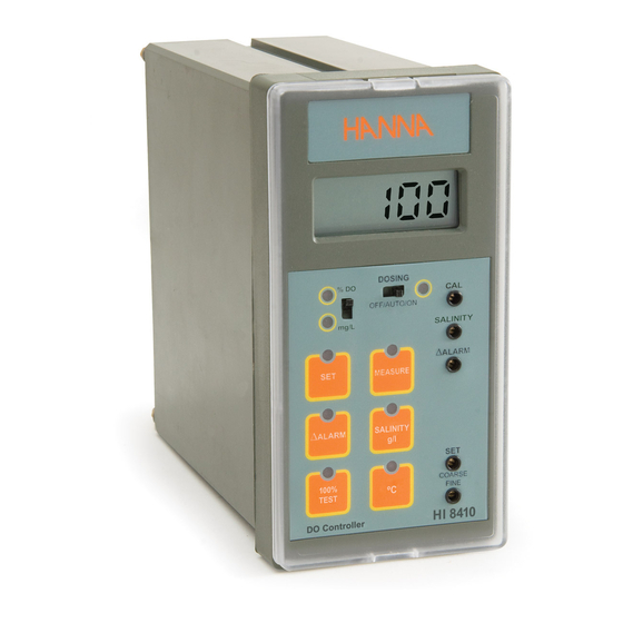
FUNCTIONAL DESCRIPTION H FUNCTIONAL DESCRIPTION H FUNCTIONAL DESCRIPTION HI I I I I 8410 8410 8410 FUNCTIONAL DESCRIPTION H FUNCTIONAL DESCRIPTION H 8410 8410 KEYPAD MEASURE To read measurements and enable diagnostic tests ΔALARM To display and set the tolerance of the alarm To display and set the working dosing point SALINITY g/L To display and set the salinity factor (active only... - Page 5 LEDS % DO To indicate that the D.O. is displayed in % of saturation mg/L To indicate that the D.O. is displayed in mg/L To indicate that the dosage is active ΔALARM To indicate an alarm condition DOSAGE MODE SWITCH To indicate that the continuous ON or OFF mode is selected from dosing switch SWITCHES OFF/AUTO/ON...
- Page 6 REAR PANEL OF HI 8410 DO probe connection terminals SET terminals for connection to a dosing pump ALARM terminals for connection to an external alarm device Power supply terminals Fuse holder mA OUTPUT terminals for connection to a recorder Hysteresis set knob (0.5 to 2.4 mg/L) Disable overtime dosing connection Overtime dosing set knob (about 5 to 60 min) Unplug the instrument from power supply before replacing the fuse.
- Page 7 MECHANICAL DIMENSIONS OF HI 8410 Front view of the panel-mounted unit These dimensions show the cutout size for the installation. Side view of the panel-mounted unit Adjustable location brackets (supplied with the meter) allow the indicator to slide into the cutout and will hold the unit securely in place. 190 mm (7.50") is the minimum amount of room required to install the indicator with the cables connected.
-
Page 8: D.o. Probes
D.O. PROBES D.O. PROBES D.O. PROBES D.O. PROBES D.O. PROBES All Hanna D.O. probes are shipped dry. To hydrate the probe and prepare it for use proceed as follows: 1. Remove the black & red plastic cap. This cap is used for ship- ping purposes only and can be thrown away. -
Page 9: Specifications Hi 8410
SPECIFICATIONS H SPECIFICATIONS HI I I I I 8410 SPECIFICATIONS H 8410 8410 8410 SPECIFICATIONS H SPECIFICATIONS H 8410 Range 0.0 to 50.0 mg/L (ppm) O 0 to 600 % O -5.0 to 50.0 °C Resolution 0.1 mg/L or 1% (O ) / 0.1 °C Accuracy ±1% of reading (O... -
Page 10: Connections
CONNECTIONS CONNECTIONS CONNECTIONS CONNECTIONS CONNECTIONS REAR CONNECTIONS FOR HI 8410 • Power Connection Terminals 4-screw-terminal-strip for connection to a 3-wire power cable according to the indicated voltage (115 or 230V). • Probe connection For connection of the HI76410 DO probe. Connect the wires according with the indicated color. - Page 11 (terminals 5, 6) • Alarm Contacts During normal operation these terminals remain closed. If the measured D.O. level is not within the tolerance of the set value, the alarm con- tact is open. These contacts act only as a switch. See also page 15. •...
-
Page 12: Operational Guide
AUTO mode The dosage is activated and deactivated ac- cording with the selected setpoint. The corre- sponding DOSAGE MODE LED (right side of the switch) is off. Be sure that the DOSAGE switch is in AUTO position when the meter is in normal operat- ing mode. - Page 13 Ensure that the HI 76410 DO probe is connected to the meter according with the colors indicated on the mask. OPERATING INFORMATION All parameters are set through the front panel keys and trimmers. When any key is pressed, the corresponding LED lights up to indicate that the function is active.
- Page 14 Press the SALINITY g/L and the display will show the salinity. Use a small screw driver to adjust the SALINITY trimmer to display the desired salinity value (within the 0 to 51 g/L range). ALTITUDE COMPENSATION (mg/L range only) When salinity compensation is not required (i.e. not salty water), the SALINITY trimmer can be used to set the altitude correction value.
-
Page 15: Taking Measurements With Hi 8410
The alarm contacts of HI 8410 remain closed during normal operation. If the measured conductivity level is not within the tolerance of the set value, the alarm contact will be open. HYSTERESIS SET Turn the hysteresis knob (rear panel) in the desired position (from 0.5 to 2.4 mg/L range) The dosage will be active according to the DO reading set point value and hysteresis set value. -
Page 16: Calibration Procedure
CALIBRATION PROCEDURE CALIBRATION PROCEDURE CALIBRATION PROCEDURE CALIBRATION PROCEDURE CALIBRATION PROCEDURE Calibration is a very simple 1-point procedure, performed in air. Ensure the probe is ready for measurements, i.e. the membrane is filled with electrolyte (see “Probe Preparation” section for details). Switch the meter on, select the % DO mode and turn the CAL trimmer to display 100%. -
Page 17: Led Indication
LED INDICATION LED INDICATION LED INDICATION LED INDICATION LED INDICATION All LEDs above the keys or near switches indicate the state of each function, whether it is active or the display is indicating the mode. % DO LED It is on if the mode selection switch is in the upper position, indicating that the selected range is % DO. -
Page 18: Probe Maintenance & Cleaning
HI 710016 Shockproof rubber boot, orange color Calibration screwdriver (20 pcs) HI 731326 * To be replaced by authorized technical personnel only. Hanna Instruments reserves the right to modify the design, construction and appearance of its products without advance notice. -
Page 19: Warranty
If the repair is not covered by the warranty, you will be notified of the charges incurred. If the instrument is to be returned to HANNA instruments , first obtain a ®... - Page 20 SALES & TECHNICAL SERVICE CONTACTS SALES & TECHNICAL SERVICE CONTACTS SALES & TECHNICAL SERVICE CONTACTS SALES & TECHNICAL SERVICE CONTACTS SALES & TECHNICAL SERVICE CONTACTS Australia: Tel. (03) 9769.0666 • Fax (03) 9769.0699 China: Tel. (10) 88570068 • Fax (10) 88570060 Egypt: Tel.