
Related Manuals for Hanna Instruments HI 9912


Summary of Contents for Hanna Instruments HI 9912
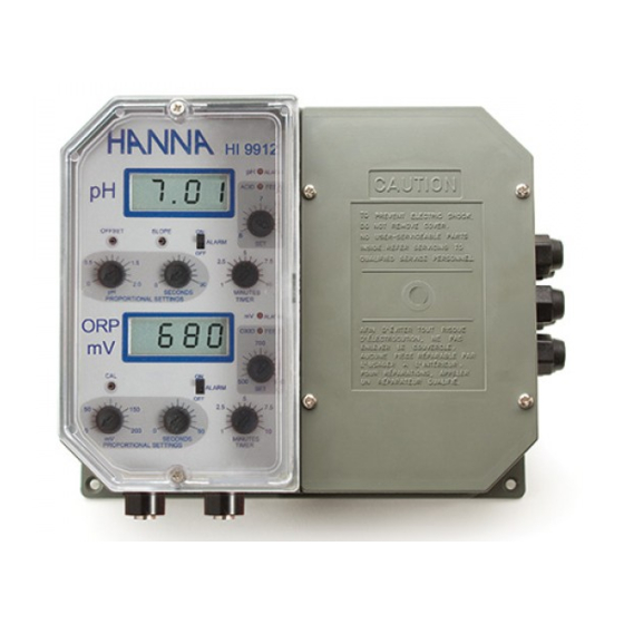
- Page 1 Instruction Manual HI 9912 Wall Mounted Dual pH/ORP Controller AL AR 10 0 20 0 A LA SE T SE T O R P LI N E These Instruments are in http://www.hannainst.com Compliance with the CE Directives...
-
Page 2: Table Of Contents
Dear Customer, Thank you for choosing a Hanna Product. Please read this instruction manual carefully before using the instru- ment. This manual will provide you with the necessary information for a correct use of the instrument, as well as a more precise idea of its versatility. -
Page 3: Preliminary Examination
PRELIMINARY EXAMINATION PRELIMINARY EXAMINATION PRELIMINARY EXAMINATION PRELIMINARY EXAMINATION PRELIMINARY EXAMINATION Remove the instrument from the packing material and examine it carefully to make sure that no damage has occurred during shipping. If there is any noticeable damage, notify your Dealer. Note: Save all packing materials until you are sure that the instrument functions correctly. -
Page 4: Mechanical Layouts
The Hanna controllers incorporate a triple contact alarm system. When activated, the alarm contacts will open or close, triggering the mechanism of your choice, whether a buzzer, light or any other electrical device. The controller is housed in a rugged, modular, fiber-reinforced ABS housing. - Page 5 Fig. 3 Figure 3 is a dimensioned, bottom view of the Wall Mounted Controller. The modular design isolates the control circuitry from the contacts making it possible to make the connections and then close the compartment. Adjustments can then be made only in the control area, without having to open the contacts compartment.
-
Page 6: Functional Diagram
FUNCTIONAL DIAGRAM HI 9912 FUNCTIONAL DIAGRAM HI 9912 FUNCTIONAL DIAGRAM HI 9912 FUNCTIONAL DIAGRAM HI 9912 FUNCTIONAL DIAGRAM HI 9912 FRONT PANEL Left panel HI 9912 ALARM ACID FEED ALARM OFFSET SLOPE ALARM SECONDS MINUTES PROPORTIONAL SETTINGS TIMER ALARM ALARM OXID FEED SET pH... - Page 7 17. Triple contact alarm in a Normally Closed (NC) or a Normally Open (NO) position 18. Powered dosage terminals for pH correction 19. Powered dosage terminals for ORP correction 20. 110/115V or 220/240V power configuration 21. Incoming power terminals 22. Fuses BOTTOM VIEW 23.
- Page 8 Specifications HI 9912 RANGE 0.00 to 14.00 pH and 0 to 1000 mV RESOLUTION 0.01 pH and 1mV ACCURACY ±0.02 pH and ±5 mV (@20°C/68°F) TYPICAL EMC ±0.1 pH and ±6 mV DEVIATION CALIBRATION Through "OFFSET" and "SLOPE" trimmers for pH and “CAL”...
-
Page 9: Connections & Wiring
CONNECTIONS & WIRING CONNECTIONS & WIRING CONNECTIONS & WIRING CONNECTIONS & WIRING CONNECTIONS & WIRING GENERAL POINTS relay terminals relay terminals powered powered • The relay terminals relay terminals relay terminals of the controller are powered powered powered. You can simply hook up your pumps or electrovalves directly to the controller and do not need additional power supply. - Page 10 Diagram) and remove the jumpers remove the jumpers remove the jumpers remove the jumpers shorting the matching remove the jumpers pin terminals. • When using a separate probe for grounding purposes, wire it to the Matching Pin terminals on the right hand panel and remove the jumpers remove the jumpers remove the jumpers (see 14 and 15 - Functional Diagram).
- Page 11 • If the actual measurements are above or below the setpoints by a margin greater than the user-selectable alarm threshold, the alarm terminal is activated, triggering the mechanism of your choice. The alarm LED lights also come on. Due to the Consent Consent Consent Consent...
-
Page 12: Normal Operation & Measurement
• For 110-115V, short the L and L1 termi- nals. Then wire the external power supply to the three terminals as shown. • Replace the cover with the gasket and screw it tight with the 4 screws provided. Only then connect the controller to the mains. Only then Only then Only then... -
Page 13: Ph Calibration
pH pH pH pH pH CALIBRATION CALIBRATION CALIBRATION CALIBRATION CALIBRATION Make sure that the pH electrode and any ground probe have been properly connected and wired to the controller (see preceding pages) and that the meter is plugged to the mains. Calibration should be performed at a tem- perature similar to that of the liquid to be monitored. -
Page 14: Orp Calibration
SLOPE ADJUSTMENT: • Rinse the electrode (and ground probe) thoroughly with water and immerse the bottom 4 cm (1.5”) in a pH 10.01 (HI 7010) or a pH 4.01 (HI 7004) buffer solution. HI 7010 • Stir the electrode and wait for the display to stabilize before adjusting the "SLOPE"... -
Page 15: Adjustement Of Setpoint(S)
ADJUSTEMENT OF SETPOINT(S) ADJUSTEMENT OF SETPOINT(S) ADJUSTEMENT OF SETPOINT(S) ADJUSTEMENT OF SETPOINT(S) ADJUSTEMENT OF SETPOINT(S) Make sure that the electrode (and any ground probe) is properly installed and calibrated (see the preceding pages). FOR pH ALARM ACID FEED Simply turn the pH ACID FEED dial (see 3 - Func- tional Diagram) and choose the desired value between 6 and 8 pH. - Page 16 to the difference between the measurement less the setpoint over the cycle. NOTE: • If the setting is left at 0 pH or 0 mV, the controller will operate as an ON/OFF control with no proportional dosage. In this case the controller will operate with a 0.1 pH or 7 mV hysteresis.
-
Page 17: Overdosage Timers
e.g. ORP proportional control Setpoint = 750 mV Measured value = 725 mV Delta = 750 - 725 = 25 mV Proportional settings = mV set to 100 and time cycle to 60 seconds The controller will be dosing oxidants to increase redox to the desired value. -
Page 18: Ph Values At Various Temperatures
pH VALUES AT VARIOUS VALUES AT VARIOUS VALUES AT VARIOUS VALUES AT VARIOUS VALUES AT VARIOUS TEMPERATURES TEMPERATURES TEMPERATURES TEMPERATURES TEMPERATURES Please refer to the following chart for a more accurate pH calibra- tion: TEMP pH VALUES °C °F 4.01 6.86 7.01 9.18... -
Page 19: Redox Measurement
R E D O X M E A S U R E M E N T R E D O X M E A S U R E M E N T R E D O X M E A S U R E M E N T R E D O X M E A S U R E M E N T R E D O X M E A S U R E M E N T Redox measurements allow the quantification of the oxidizing or... -
Page 20: Electrode Conditioning & Maintenance
The protective cap should also be filled with a few drops of HI 70300 storage solution if the electrode is not being used at all. Note: With industrial applications, it is always good practice to keep at least one spare electrode handy. When anomalies are not resolved with a simple maintenance, change the electrode to see if the problem is alleviated. -
Page 21: Suggested Installations For Ph/Orp Electrodes
For more specific cleaning procedures, refer to the electrode’s instruc- tion manual. IMPORTANT: After performing any of the cleaning procedures rinse the electrode thoroughly with distilled water and recalibrate the controller. TROUBLESHOOTING Evaluate your electrode performance based on the following. •... -
Page 22: Accessories
This type of connection is very delicate and requires constant attention to maintain proper operating conditions. The conventional electrodes may be used for indoor applications but the cable length should not exceed 10 m (33'). MEDIUM DISTANCE, INDOOR/OUTDOOR INSTALLATION When an outdoor installation is required, it is normally necessary to install a transmitter to obtain accurate readings at distances from 10 to 50 m (33-165'). - Page 23 specific handbooks for process instrumentation, or simply call the Hanna office nearest to you for a complete list. pH CALIBRATION SOLUTIONS HI 7004L pH 4.01 buffer solution, 460 mL HI 7007L pH 7.01 buffer solution, 460 mL HI 7010L pH 10.01 buffer solution, 460 mL ORP SOLUTIONS HI 7020L 200-275mV ORP solution, 460 mL...
-
Page 25: Warranty
Hanna Instruments Inc., 584 Park East Drive, Woonsocket, Rhode Island, 02895 , USA. Hanna Instruments reserves the right to modify the design, construction and appearance of its products without advance notice. -
Page 26: Other Products From Hanna
OTHER PRODUCTS FROM HANNA OTHER PRODUCTS FROM HANNA OTHER PRODUCTS FROM HANNA OTHER PRODUCTS FROM HANNA OTHER PRODUCTS FROM HANNA • CABLES AND CONNECTORS • CALIBRATION AND MAINTENANCE SOLUTIONS • CHEMICAL TEST KITS • CHLORINE METERS • CONDUCTIVITY/TDS METERS • DISSOLVED OXYGEN METERS •... -
Page 27: Ce Declaration Of Conformity
CE DECLARATION OF CONFORMITY CE DECLARATION OF CONFORMITY CE DECLARATION OF CONFORMITY CE DECLARATION OF CONFORMITY DECLARATION OF CONFORMITY Hanna Instruments Srl V.le delle industrie 12 35010 Ronchi di Villafranca (PD) ITALY herewith certify that the wall-mounted instrument: HI 9912... - Page 28 HANNA LITERATURE HANNA LITERATURE HANNA LITERATURE HANNA LITERATURE HANNA LITERATURE Hanna publishes a wide range of catalogs and hand- books for an equally wide range of applications. The reference literature currently covers areas such as: • Water Treatment • Process •...