Table of Contents

Related Manuals for Hanna Instruments HI 9923


Summary of Contents for Hanna Instruments HI 9923
-
Page 1: Instruction Manual
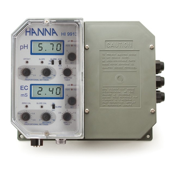
Instruction Manual HI 9913 - HI 9923 HI 9935 Wall Mounted Dual Conductivity/TDS & pH Controllers A L A R A L A S E T S E T L IN E These Instruments are in http://www.hannainst.com Compliance with the CE Directives... -
Page 2: Table Of Contents
Dear Customer, Thank you for choosing a Hanna Product. Please read this instruction manual carefully before using the instru- ment. This manual will provide you with the necessary information for a correct use of the instrument, as well as a more precise idea of its versatility. -
Page 3: Preliminary Examination
PRELIMINARY EXAMINATION PRELIMINARY EXAMINATION PRELIMINARY EXAMINATION PRELIMINARY EXAMINATION PRELIMINARY EXAMINATION Remove the instrument from the packing material and examine it carefully to make sure that no damage has occurred during ship- ping. If there is any noticeable damage, notify your Dealer. Note: Save all packing materials until you are sure that the instrument functions correctly. -
Page 4: Mechanical Layouts
The controllers come equipped with relays operating at a maximum of 2A (240V). They incorporate a triple contact alarm system. When activated, the alarm contacts will open or close, triggering the mechanism of your choice, whether a buzzer, light or any other electrical device. The controllers are housed in a rugged, modular, fiber-reinforced ABS housing. - Page 5 Fig. 3 Figure 3 is a dimensioned, bottom view of the wall mounted controller. The modular design isolates the control circuitry from the contacts making it possible to make the connections and then close the compartment. Adjustments can then be made only in the control area, without having to open the contacts compartment.
-
Page 6: Functional Diagram Hi 9913
FUNCTIONAL DIAGRAM HI 9913 FUNCTIONAL DIAGRAM HI 9913 FUNCTIONAL DIAGRAM HI 9913 FUNCTIONAL DIAGRAM HI 9913 FUNCTIONAL DIAGRAM HI 9913 FRONT PANEL HI 9913 ALARM ACID FEED ALARM ALARM ACID OFFSET SLOPE ALARM SECONDS MINUTES PROPORTIONAL SETTINGS TIMER SET pH ALARM FERT FEED... - Page 7 20. Triple contact alarm in a Normally Closed (NC) or a Normally Open (NO) position. 21. Powered dosage terminals (Relay) for pH correction 22. Powered dosage terminals (Relay) for EC correction 23. 110/115V or 220/240V power configuration 24. Incoming power terminals 25.
- Page 8 Specifications HI 9913 RANGE 0.00 to 14.00 pH and 0.00 to 10.00 mS/cm (EC) RESOLUTION 0.01 pH and 0.01 mS/cm ACCURACY ±0.02 pH and ±2% F. S. (@20°C/68°F) TYPICAL EMC ±0.1 pH and ±2% F. S. DEVIATION Through "OFFSET" and "SLOPE" trimmers for pH, and CALIBRATION “ZERO CAL”...
-
Page 9: Functional Diagram Hi 9923
FUNCTIONAL DIAGRAM HI 9923 FUNCTIONAL DIAGRAM HI 9923 FUNCTIONAL DIAGRAM HI 9923 FUNCTIONAL DIAGRAM HI 9923 FUNCTIONAL DIAGRAM HI 9923 FRONT PANEL HI 9923 ALARM FEED ALARM OFFSET SLOPE AUTO MANUAL ALARM MINUTES TIMER SET pH ALARM BLEED SET EC ZERO CAL SLOPE CAL AUTO... - Page 10 23. 110/115V or 220/240V power configuration 24. Incoming power terminals 25. Fuses BOTTOM VIEW 26. Female BNC connector for a combination pH electrode 27. 4-mm Banana socket for the pH ground probe 28. Female DIN connector for conductivity probe Unplug the instrument from the power supply before wiring or replacing the fuses.
- Page 11 Specifications HI 9923 RANGE 0.00 to 14.00 pH and 0.00 to 10.00 mS/cm (mmho/cm) RESOLUTION 0.01 pH and 0.01 mS/cm (mmho/cm) ACCURACY ±0.02 pH and ±2% F. S. (@20°C/68°F) TYPICAL EMC ±0.1 pH and ±2% F. S. DEVIATION Through "OFFSET" and "SLOPE" trimmers for pH, and CALIBRATION “ZERO CAL”...
-
Page 12: Functional Diagram Hi 9935
FUNCTIONAL DIAGRAM HI 9935 FUNCTIONAL DIAGRAM HI 9935 FUNCTIONAL DIAGRAM HI 9935 FUNCTIONAL DIAGRAM HI 9935 FUNCTIONAL DIAGRAM HI 9935 FRONT PANEL HI 9935 ALARM ACID FEED ALARM OFFSET SLOPE ALARM ALARM SECONDS MINUTES PROPORTIONAL SETTINGS TIMER SET pH ALARM FERT FEED SET EC... - Page 13 21. Powered dosage terminals (Relay) for pH correction 22. Powered dosage terminals (Relay) for TDS correction 23. 110/115V or 220/240V power configuration 24. Incoming power terminals 25. Fuses BOTTOM VEW 26. Female BNC connector for a combination pH electrode 27. 4-mm Banana socket for the pH ground probe 28.
-
Page 14: Connections & Wiring
Specifications HI 9935 RANGE 0.00 to 14.00 pH and 0.00 to 1999 ppm (mg/L) RESOLUTION 0.01 pH and 1 ppm (mg/L) ACCURACY ±0.02 pH and ±2% F. S. (@20°C/68°F) TYPICAL EMC ±0.1 pH and ±2% F. S. DEVIATION Through "OFFSET" and "SLOPE" trimmers for pH, and CALIBRATION “ZERO CAL”... - Page 15 • Unscrew the 4 screws on the right hand panel and remove the cover and the gasket. Thread the wires through the access ports on the right hand side of the controllers. • Before Before connecting the controller to the mains, wire connecting the controller to the mains, wire connecting the controller to the mains, wire connecting the controller to the mains, wire...
- Page 16 CONDUCTIVITY/TDS PROBE CONNECTION • Attach the conductivity/TDS probe (HI 3002, HI 3001D or HI 7638) to the DIN socket located on the bottom of the casing. Align the guide on the connector with the socket, push the connector in and tighten the retainer ring. (HI 3002 is more suitable for direct immersion in the tank, vat or pipes.
- Page 17 • The operator can similarly select an alarm threshold of 0.0 to 2.0 mS/cm (HI 9913 and HI 9923) or 0 to 400 ppm (HI 9935) by turning the alarm ALARM ALARM knob (see 19 - Functional Diagram). If the conductivity/TDS measurements ex- ceed the setpoint (HI 9913 and HI 9935) or the conductivity falls below the setpoint (HI 9923) by a margin greater than the user-...
- Page 18 • The alarm is also activated if one or both of the independent maximum dosage times are exceeded. The maximum time that the relay contacts remain active continuously (max. dosage time) can be set from 1 to 10 minutes for HI 9913 and MINUTES ALARM DOSING TIME HI 9935 and 1 to 90 minutes for HI 9923.
-
Page 19: Normal Operation & Measurement
NORMAL OPERATION & NORMAL OPERATION & NORMAL OPERATION & NORMAL OPERATION & NORMAL OPERATION & MEASUREMENT MEASUREMENT MEASUREMENT MEASUREMENT MEASUREMENT Make sure that the controller has been properly calibrated before commencing and that the pH and conductivity/TDS setpoints have been adjusted (see following pages). The pH electrode, conductivity/TDS probe and any ground probe must be properly connected and wired to the controller (see preceding pages). -
Page 20: Ph Calibration
pH pH pH pH pH CALIBRATION CALIBRATION CALIBRATION CALIBRATION CALIBRATION Make sure that the pH electrode and any ground probe have been properly connected and wired to the controller (see preceding pages) and that the meter is plugged to the mains. Calibration should be performed at a temperature similar to that of the liquid to be monitored. -
Page 21: Conductivity/Tds Calibration
• If the temperature of the buffer solution is not 25°C (77°F), refer to the chart at the end of the manual for the appropriate buffer value at a given temperature and adjust the trimmer accordingly. SLOPE ADJUSTMENT: • Rinse the electrode (and ground probe) thoroughly with water and immerse the bottom 4 cm (1.5”) in a pH 10.01 (HI 7010) or a pH 4.01 (HI 7004) buffer... - Page 22 ments are in the 1.2 to 2.5 EC range. Similarly, utilize HI 7039L with a value of 5.00 mS/cm at 25 °C if controlling your process with HI 9923 and HI 70442L with a value of 1500 ppm (mg/L) value if working with HI 9935. •...
- Page 23 ADJUSTEMENT OF SETPOINTS ADJUSTEMENT OF SETPOINTS ADJUSTEMENT OF SETPOINTS ADJUSTEMENT OF SETPOINTS ADJUSTEMENT OF SETPOINTS Make sure that the pH electrode, conductivity/TDS probe and any ground probe have been properly installed and calibrated (see the preceding pages). FOR pH Simply turn the pH ACID FEED or ALK FEED dial (see ACID FEED 3 - Functional Diagram).
-
Page 24: Proportional Control
P R O P O R T I O N A L C O N T R O L P R O P O R T I O N A L C O N T R O L P R O P O R T I O N A L C O N T R O L P R O P O R T I O N A L C O N T R O L P R O P O R T I O N A L C O N T R O L (HI 9913 &... - Page 25 e.g. EC proportional control for HI 9913 Setpoint = 2.20 mS/cm (EC) Measured value = 1.45 mS/cm Delta = 2.20 - 1.45 = 0.75 mS/cm Proportional settings = EC set to 1 and time cycle to 60 seconds The controller will be dosing fertilizers to increase the EC to the desired limit.
-
Page 26: Conductivity Dead Band (Hi 9923)
e.g. HI 9935 proportional control Setpoint = 1600 ppm (TDS) Measured value = 1550 ppm Delta = 1600 - 1550 = 50 ppm Proportional settings = ppm set to 200 and time cycle to 60 seconds The controller will be dosing fertil- D ppm izers to reach the desired value. -
Page 27: Ph Values At Various Temperatures
With HI 9913 and HI 9935, the cycles are selectable from 1 to 10 minutes for both pH and EC/TDS. For HI 9923 instead, the timers can be set from 1 to 90 MINUTES TIMER minutes to allow for proper blow down of the boiler or cooling tower. -
Page 28: Ph Electrode Conditioning & Maintenance
pH ELECTRODE CONDITIONING pH ELECTRODE CONDITIONING pH ELECTRODE CONDITIONING pH ELECTRODE CONDITIONING pH ELECTRODE CONDITIONING & MAINTENANCE & MAINTENANCE & MAINTENANCE & MAINTENANCE & MAINTENANCE PREPARATION Remove the protective cap. DO NOT BE ALARMED IF ANY SALT DEPOSITS ARE PRESENT. This is normal with electrodes and they will disappear when rinsed with water. -
Page 29: Conductivity/Tds Probe Cleaning & Maintenance
TROUBLESHOOTING Evaluate your electrode performance based on the following. • Noise (Readings fluctuate up and down) could be due to clogged/dirty junction: Refer to the Cleaning Procedure above. • Dry Membrane/Junction: Soak in Storage Solution HI 70300 overnight. Check to make sure the installation is such as to create a well for the electrode bulb to constantly remain moist. -
Page 30: Suggested Installations For Ph Electrode
CLEANING PROCEDURE Remove the sleeve and soak the probe in a Hanna HI 7061 General Cleaning Solution for 1 hour. If the probe has been left in highly concentrated fertilizer solution and does not seem to become clean, repeat the cleaning procedure. The rings can also be cleaned with a cloth. -
Page 31: Suggested Installations For Ec/Tds Probe
The conventional electrodes may be used for indoor applications but the cable length should not exceed 10 m (33'). MEDIUM DISTANCE, INDOOR/OUTDOOR INSTALLATION When an outdoor installation is required, it is normally necessary to install a transmitter to obtain accurate readings at distances from 10 to 50 m (33-165'). - Page 32 HI 3002 FOR IN-LINE INSTALLATION The drawing illustrates the ideal installation system since the stream pressure in the pipe forces the air bubbles out automatically. HI 3001D illustrated preaviously can also be mounted in this fashion. However the longer HI 3002 stem of HI 3002 fa- cilitates an easier >...
-
Page 33: Accessories
A C C E S S O R I E S A C C E S S O R I E S A C C E S S O R I E S A C C E S S O R I E S A C C E S S O R I E S pH ELECTRODES HI 1002/3... -
Page 34: Warranty
OTHER ACCESSORIES BL PUMPS Dosing pumps (several models are available with flow rates from 1.5 to 18.3 lph / 0.4 to 4.8 gph) ChecktempC Pocket-size thermometer (range -50.0 to 150.0°C) ChecktempF Pocket-size thermometer (range -58.0 to 302.0°F) HI 6050 Submersible pH electrode holder (605 mm/23.8" total length) HI 6051 Submersible pH electrode holder (1105 mm/43.5"... -
Page 35: Ce Declaration Of Conformity
Hanna Instruments Inc., 584 Park East Drive, Woonsocket, Rhode Island, 02895 , USA. Hanna Instruments reserves the right to modify the design, construction and appearance of its products without advance notice. - Page 36 HANNA LITERATURE HANNA LITERATURE HANNA LITERATURE HANNA LITERATURE HANNA LITERATURE Hanna publishes a wide range of catalogs and hand- books for an equally wide range of applications. The reference literature currently covers areas such as: • Water Treatment • Process •...