
Related Manuals for Hanna Instruments HI 24 Series


Summary of Contents for Hanna Instruments HI 24 Series
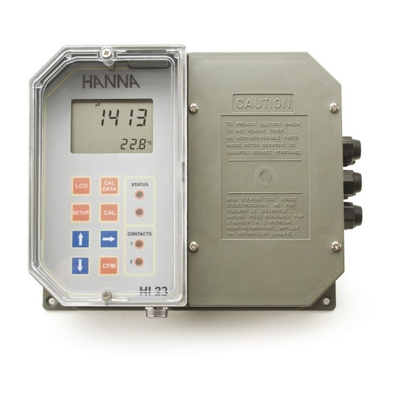
- Page 1 HI 23 / HI 24 Series Wall-mounted, Microprocessor-based, Conductivity and TDS Process Controllers Instruction Manual...
-
Page 2: Table Of Contents
If you need additional technical information, do not hesitate to e-mail us at tech@hannainst.com These instruments are in compliance with the directives. © 2001 Hanna Instruments All rights are reserved. Reproduction in whole or in part is prohibited without the written consent of the copyright owner. -
Page 3: Preliminary Examination
PRELIMINARY EXAMINATION Remove the instrument from the packing material and exam- ine it carefully to make sure that no damage has occurred during shipping. If there is any noticeable damage, notify your Dealer or the nearest Hanna Customer Service Center immediately. -
Page 4: Functional Description
• Calibration and Setup procedures allowed only through FUNCTIONAL DESCRIPTION an unlock password. • Calibration: 2 points with Hanna EC and TDS calibration solutions. • Four different EC working ranges (0 to 199.9 S; 0 to 1999 S; 0 to 19.99mS; 0 to 199.9mS). •... -
Page 5: Mechanical Dimensions
MECHANICAL DIMENSIONS RS 485 communications terminal (HI 23xy2 and HI 24xy2 models only) Analog Output terminal (HI 23xy1 and HI 24xy1 models only) Pt 100 Temperature Sensor terminal Power supply output for external transmitter 4-20 mA input from external transmitter Main Power Supply Alarm Terminal Contact 1 - First Dosing Terminal... -
Page 6: Specifications
SPECIFICATIONS INSTALLATION Range 0.0 to 199.9 µS/cm, 0 to 1999 µS/cm HI 23 and HI 24 series offer a multitude of possibilities, 0.00 to 19.99 mS/cm, 0.0 to 199.9 mS/cm from dual setpoints to ON/OFF or PID dosage, isolated out- 0.0 to 100.0 ppm, 0 to 1000 ppm (HI 24 series only)* puts with user-selectable zoom, recorder outputs in mA and 0.00 to 10.00 ppt, 0.0 to 100.0 ppt (HI 24 series only)*... - Page 7 • Power Supply: Connect a 3-wire power If the Pt 100 has more than 2 wires, con- cable to the terminal strip, while paying nect the two wires of one end to pins 9 attention to the correct line (L), earth (PE) and 10 (pin 9 is an auxiliary input to and neutral (N) terminal connections.
-
Page 8: Setup Mode
The setup codes can be selected Connect the two signal wires from the transmitter to terminals after password and CFM are #5 on page 8, paying attention to the correct polarity. Termi- pressed. When CFM is pressed, nal 14 is the positive input and terminal 15 is the negative the current setup item is saved input. - Page 9 Note The default password is set at “0000”. SETUP CODES • The LCD will display “SET” on the up- The following table lists the setup codes along with the descrip- per part and “c.00” on the lower, al- tion of the specific setup items, their valid values and whether lowing the user to edit setup param- password is required to view that item (“PW”...
- Page 10 Code Valid Values Default Code Valid Values Default 71 Baud rate 1200, 2400, 4800, 9600 4800 21 Relay 2 mode (M2) same as relay 1 72 Cleaning timer 0 to 19999 days 22 Relay 2 setpoint (S2) 0.5 to 99.5% full scale 75% f.s.
-
Page 11: Control Mode
If M2= 1 then S2-H2 LA; CONTROL MODE If M2= 2 then S2+H2 HA; The control mode is the normal operational mode for these If M2= 3 then S2+D2 HA; meters. During control mode the meter fulfills the following If M2= 4 then S2-D2 LA; main tasks: If M1= 1 and M2 = 2 •... - Page 12 An upper boundary is imposed for dosage time when relays de-energized when the EC value is above the setpoint plus are energized continuously, i.e. when relay works in ON/ the hysteresis. OFF mode or also in PID mode but in the latter case only if the relay is always ON.
- Page 13 second is the integrative action and the third is the deriva- tive action. The derivative function (rate action) compensates for rapid changes in the system reducing undershoot and overshoot Proportional action can be set by means of the Proportional of the EC or TDS value. Band (PB).
- Page 14 The user can vary five different parameters, i.e. the setpoint 4. The deviation, Ti and Td can be calculated from the following: (S1 or S2), the deviation (D1 or D2), the reset time, the rate • Deviation = Tx * max. slope (EC/TDS) time and the proportional control mode period T (from 1 •...
-
Page 15: Idle Mode
Moreover the alarm signal is generated only after a user selectable time period (alarm mask) has elapsed since the controlled value has overtaken one alarm threshold. This additional feature will avoid fake or temporary alarm con- ditions. Note If the power supply is interrupted, the relay is de-energized as if in alarm condition to alert the operator. -
Page 16: Analog Output
The type (voltage or current) and the range of the output analog signal is selectable through the jumpers on the board. Analog output options are as follows: 0-5 VDC; 1-5 VDC 0-10 VDC (default) 0-20 mA; 4-20 mA (default) 0-1 mA Control actions are stopped as soon as the Choice between different ranges with the same configura- user presses SETUP and enters the pass-... -
Page 17: Calibration
To obtain accurate readings, use the calibration solution in CALIBRATION the selected range and closer to the values to be mea- sured. The controller is factory calibrated for temperature as well as Offset Calibration for the analog input and outputs. •... - Page 18 • When the reading is stable, "CAL" will stop CELL CONSTANT DIRECT SELECTION flashing (after about 30 seconds) and Whenever the EC/TDS probe cell constant is known, it is "CFM" indicator will blink. possible to directly calibrate the meter using that value. •...
- Page 19 Calibration procedure may be interrupted by pressing CAL again at any time. If the calibration procedure is stopped this way, or if the controller is switched off before the last step, no calibration data is stored in nonvolatile memory (EE- PROM).
- Page 20 • Press CFM to confirm. The meter will return to normal op- OUTPUT CALIBRATION CALIBRATION CALIBRATION erational mode. TYPE CODE POINT 1 POINT 2 Calibration procedure may be interrupted by pressing CAL again at any time. If the calibration procedure is stopped 0-1 mA 0 mA 1 mA...
-
Page 21: Last Calibration Data
Note When adjusting values using the keys it is important to allow for sufficient response time (up to 30 seconds) The table below lists the values of output codes along with the calibration point values (which are the analog output minimum and the analog output maximum) as indicated •... - Page 22 A I2C failure is detected when the I2C transmission is not As soon as one or more keys are pressed, the appropriate acknowledged or a bus fault occurs for more than a certain segments out of 88:88 corresponding to the pressed keys, number of attempts (this can be due, for example, to dam- will light up on the screen.
-
Page 23: External Functions
EEPROM SELFTEST WATCHDOG The EEPROM selftest procedure involves verifying the stored When a dead loop condition is detected a reset is auto- EEPROM checksum. If the checksum is correct the “Stored matically invoked. data good” message will be shown for a few seconds be- The effectiveness of watchdog capability can be tested fore exiting selftest procedure. -
Page 24: Rs 485 Communication
Up to 32 units can be connected to the same RS485 line, RS 485 COMMUNICATION with a total line length of up to 1.2 Km using 24AWG cable. To minimize electromagnetic interference, use shielded or HI 23xy2 and HI 24xy2 are provided with an RS485 port. twisted pair cable to connect the units. - Page 25 • Using the arrow keys, set the null Same as LCD key controller address. To exit setup, null Same as key press CFM key and then LCD key. null Same as key Note In an RS 485 network, each device must have a different address.
- Page 26 “01SET33+015••<CR>” The time-out for the first character of the controller answer is 100 milliseconds. This command sets the setup item 33 (max. relay ON time) of a controller, identified by the process ID number 01, to 15 minutes. The • character means blank. The minim delay between the last received character and first character of the answer is 15 ms.
-
Page 27: Startup
STARTUP “03<STX>10.7D<ETX>” meaning that the current temperature reading is 10.7°C, the During the automatic startup the Real Time Clock (RTC) is control action is active and no alarm condition is present checked to see if a reset occurred since last software initial- and controller setup is modified (must update controller setup ization. -
Page 28: Ec Values At Various Temperatures
EC VALUES AT VARIOUS TEMPERATURES EC / TDS PROBE MAINTENANCE Temperature has a significant effect on conductivity. Table Probe can be compensated for normal contamination by a below shows EC values at various temperatures for the process of recalibration. When calibration can no longer Hanna calibration solutions. -
Page 29: Accessories
ACCESSORIES CONDUCTIVITY CALIBRATION SOLUTIONS OTHER ACCESSORIES HI 7030L 12880 µS/cm solution, 500 mL bottle HI 3011D 4-ring EC/TDS probe with standard 1/2’’ external thread for flow-thru mounting, DIN connector and 3 m (10’) cable HI 7030M 12880 µS/cm solution, 230 mL bottle HI 3012D 4-ring EC/TDS probe with standard 1/2’’... -
Page 30: Warranty
If the repair is not covered by the warranty, you will be notified of the charges incurred. If the instrument is to be returned to Hanna Instruments, first obtain a Returned Goods Authorization number from the Customer Service department and then send it with shipping costs prepaid. - Page 31 TECHNICAL SERVICE CONTACTS Australia: Tel. (03) 9769.0666 • Fax (03) 9769.0699 China: Tel. (10) 88570068 • Fax (10) 88570060 Egypt: Tel. & Fax (02) 2758.683 Germany: Tel. (07851) 9129-0 • Fax (07851) 9129-99 Greece: Tel. (210) 823.5192 • Fax (210) 884.0210 Indonesia: Tel.