Epson LQ 1050 - B/W Dot-matrix Printer Technical Manual
Technical manual
Hide thumbs
Also See for LQ 1050 - B/W Dot-matrix Printer:
- User manual (222 pages) ,
- Paper manual (8 pages) ,
- Product support bulletin (18 pages)
Table of Contents
Advertisement
Quick Links
Download this manual
See also:
User Manual
Advertisement
Chapters
Table of Contents

Related Manuals for Epson LQ 1050 - B/W Dot-matrix Printer


Summary of Contents for Epson LQ 1050 - B/W Dot-matrix Printer
- Page 1 FX-85t3/I05D TECHNICAL MANUAL EPSON...
- Page 2 However, should any errors be detected, SEIKO EPSON would greatly appreciate being informed of them. “ The above notwithstanding SEIKO EPSON can assume no responsibility for any errors in this manual or the consequences thereof. (L Copyright 1988 by SEIKO EPSON CORPORATION...
- Page 3 Chapter 4 - Includes a step-by-step guide for product disassembly, assembly, and adjustment. Chapter 5 - Provides Epson-approved techniques for troubleshooting. Chapter 6 - Describes preventive maintenance techniques and lists lubricants and adhesives required to service the equipment. The contents of this manual are subject to change without notice.
- Page 4 REV.-A g,}, REVISION TABLE ..REVISION DATE ISSUED CHANGE DOCUMENT 1st issue February 15, 1988 f--;...
- Page 5 UCT HAS A PRIMARY-AC RATING DIFFERENT FROM THE AVAILABLE POWER SOURCE, DO NOT CONNECT IT TO THE POWER SOURCE. 3. ALWAYS VERIFY THAT THE EPSON PRODUCT HAS BEEN DISCONNECTED FROM THE POWER SOURCE BEFORE REMOVING OR REPLACING PRINTED CIRCUIT BOARDS AND/OR INDIVIDUAL CHIPS.
- Page 6 REV.-A TABLE OF CONTENTS CHAPTER 1. GENERAL DESCRIPTION CHAPTER 2. OPERATING PRINCIPLES CHAPTER 3. OPTIONAL EQUIPMENTS (Intentionally omitted at this time) CHAPTER 4. DISASSEMBLY, ASSEMBLY, AND ADJUSTMENT CHAPTER 5. TROUBLESHOOTING M A I N T E N A N C E CHAPTER 6.
-
Page 7: Table Of Contents
REV.-A CHAPTER 1 GENERAL DESCRIPTION FEATURES ................... . . 1-1 SPECIFICATIONS . - Page 8 REV.-A “’” Cut Sheet Paper Printable Area ........1-6 Figure 1-3.
- Page 9 REV.-A Table 1.19. DIP Switch 1 Settings ............
-
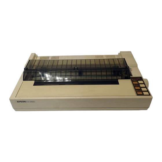
Page 10: Figure 1-1. Exterior Views Of The Fx-850/1050
Two NLQ fonts (Roman and Saris-serif) are standard. Printer driver EPSON ESC/P-83 is standard. (This driver is compatible with the high class models such as FX-800, -1000, -86e, and -286e.) Double-height function Pitch control is possible in the NLQ mode. - Page 11 REV.-A Table 1-1. Optional Units FX-1 050 FX-850 Name Roll Paper Holder #83 10 #731 1 Pull Tractor Unit Pull Tractor Unit #731 2 Cut Sheet Feeder (single-bin) # 7 3 3 9 Cut Sheet Feeder (single-bin) # 7 3 4 0 # 8 7 5 0 Ribbon Cartridge #8755 (M) Ribbon Cartridge...
-
Page 12: Hardware Specifications
REV.-A 1.2 SPECIFICATIONS with a wide variety of host computers. This section describes the The FX-850/l 050 communicates specifications for the printer. 1.2.1 Hardware Specifications Serial, impact dot matrix Printing Method See Figure 1-2 (diameter: 0.29 mm). Pin Configuration Wires 1’... - Page 13 REV.-A Do not perform reverse feeding for more than 1/6 inches. f’” Because accuracy of paper feed cannot be assured, do not perform reverse feeding ‘ after the paper end has been detected. b) When using pull tractor feed: Remove the paper tension unit and mount the pull tractor unit. Use the paper path when a single sheet is inserted.
- Page 14 Refer to Table 1-5. Fanfold Table 1-5. Fanfold Paper Specified Conditions FX-1 050 FX-850 101 - 254 (4.0 - 10.0”) 101 - 406 (4.0 - 16.0”) ~ Width [mm] [sheet] 4 (1 original + 3 ) at normal temperature Copies 3 (1 original + 2 ) at all temperature range Plain paper Quality...
-
Page 15: Cut Sheet Paper Printable Area
REV.-A f:,,, Refer to Table 1-8. Label Table 1-8. Label Specifications FX-850/l 050 [mm] 63.5 X 2.38 (2.5 X 15/16”), Size 101.6 X 2.38 (4 X 15/1 6“) 101.6 X 36.5 (4 X 1 7/1 6“) less than 0.19 (0.0075”) Thickness [mm] Printable Area See Figure 1-3. -
Page 16: Fanfold Paper Printable Area
REV.-A See Figure 1-4. Fanfold paper 10*~(16)”, 254(406)mm Printable area J * 2 ~ 350)mm Max. 203.3( ,8”(13.8”) Printable area o ABC 0.36”, 9mm or more! - - - - - - - - - - - - - - - - - - - - - - - - - - - 0.35”, 9mm or more X’iz... -
Page 17: Figure 1-5. Head Adjustment Lever Positioning
REV.-A :!,, normal temperature. Printing of labels is only available at NOTES: 1. Labels must be fanfold. must be jointed by pasting along the dots or lines, Labels with pressure-sensitive paper than or equal to 0.3 mm (O. 11 8“) to be printed out and the total thickness must be less under conditions that must be between 5 to 35 “C and 20 to 80Y0 RH. - Page 18 Dimensions See Table 1-11 (Details are shown in Figures A-45 and 46.). Weight See Table 1-11. Table 1-11. Dimensions and Weight Depth [mm] Weight [Kg] Width [mm] Height [mm] FX-850 4 3 0 12.5 FX-I 050 NOTE: Excluding platen knob and paper guide. Electrical Specifications See Table 1-12.
-
Page 19: Firmware Specifications
REV.-A Safety Approvals UL4785th (U.S.A. version) Safety standards CSA22.2#220 VDE0806 (TUV) (European version) Radio Frequency (RFI) FCC class B (U.S.A. version) VDE871 (European version) Interference 1.2.2 Firmware Specifications ESC/P-83 Control Code Printing Direction Bidirectional printing with logic seeking Text Unidirectional printing Bit-image 8 bits Character Code... - Page 20 Refer to Table 1-15. Print Columns Table 1-15. Print Columns Printable Columns IcPI] Type of Letters FX-1 050 FX-850 Normal Condensed Elite Condensed elite NOTE: In Condensed mode, printable column is always 137. (Previous FX series is 132.) Character Size, Pitch Refer to Table 1-16.
-
Page 21: Interface Overview
REV.-A 1.3 INTERFACE OVERVIEW The FX-850/l 050 has 8-bit parallel interface as standard. 1.3.1 8-bit Parallel Interface Specifications 8-bit pallarel Data Transmission Mode By STROBE pulse Synchronization By BUSY and ACKNLG (either or both) Handshaking TTL compatible Logic Level See Figure 1-6. Data Transmission Timing 57-30360 (AMPHENOL) or equivalent Connector... - Page 22 n -.
- Page 23 REV.-A Table 1-17 shows the connector pin assignments and signal functions of the 8-bit parallel interface. . . , ’ < Table 1-17. Connector Pin Assignments and Signal Function Functional Description Return Pin No. Pin No. Signal Name Strobe pulse to read the input data. Pulse width must STRORE be more than 0.5#s.
- Page 24 REV.-A Table 1-17. Connector Pin Assignments and Signal Function (cent’d) Pin No. Signal Name Return Pin No. Functional Description Same as with Pin No. 19 to 30. Not used. Pulled up to +5V through 3.3 K ohms resistor. The DC l/DC3 code is only valid when this signal is SLCT-IN “HIGH”...
- Page 25 REV.-A :):> Table 1-18 shows the printer select/deselect (DC l/DC3) control, including relations among ON-LINE, SLCT-IN input, DC 1 /DC3, and interface signals. Table 1-18. Printer Select/Deselect Control DATA ENTRY ACKNLG Dcl/Dc3 ERROR BUSY ON-LINE SW SLCT-IN No pulse Disable OFF-LINE HIGH/LOW DC l/DC3...
-
Page 26: Dip Switches And Jumper Setting
Protocol mode When DIP switch 1-4 is ON, printer operates in the IBM emulation mode; when off, printer operates in the Epson ESC/P mode. Functions of DIP switches 1-6, 1-7, and 1-8 are different when using the printer in the IBM emulation mode. - Page 27 REV.-A ,,# ,. Table 1-20. International Character Set IBM CG Table SW 1-8 Country WV 1-6 Table 1 France Germany CG Table 2 Denmark Sweden Italy Spain NOTE: When DIP SW1-4 is on (IBM mode), the functions of DIP SW1-6 through SW1-8 change to IBM character generator selection.
-
Page 28: Self Test Operation
REV.-A 1.5 SELF TEST OPERATION The FX-850/l 050 printer has the following self test (self printing) function which checks the following: Control Circuit Functions Printer Mechanism Functions Print Quality DIP Switch Settings Table 1-23 lists the self test operating instructions and Figure 1-8 shows the self test printing. Table 1-23. -
Page 29: Features
REV.-A 1.6 HEXADECIMAL DUMP FUNCTION The hexadecimal dump function causes the printer to print the received data in hexadecimal. The printer prints 16 values in hexadecimal, followed by the corresponding ASCII characters, on one line. If there is no corresponding printable character for a value (i.e. a control code), a period (.) is printed. Any remaining data (less than 16 values) can be printed by operating the ON LINE switch. -
Page 30: Printer Initialization
REV.-A 1.7 PRINTER INITIALIZATION There are two initialization methods: hardware initialization and software initialization. 1.7.1 Hardware Initialization This type of initialization occurs when printer power is turned on or when the printer receives the INIT signal from the host computer via the 8-bit parallel interface. When printer is initialized in this way, it performs the following actions: Initializes printer mechanism. -
Page 31: Buzzer Operation And Error Conditions
REV.-A 1.8 BUZZER OPERATION AND ERROR CONDITIONS This section describes the buzzer operation and error conditions of the printer. 1.8.1 Buzzer Operation The buzzer beeps as follows: When a BEL code is sent to the printer, the buzzer sounds for 0.1 second. When the following error has occured: Beeps 6 times, pausing briefly after 3rd beep. -
Page 32: Paper Handling Functions
REV.-A 1.9 PAPER HANDLING FUNCTIONS The push tractor unit can be easily mounted or removed using the paper release lever. Either continuous paper or cut sheets can be easily selected by operating the LOAD/EJECT switch and paper release lever. Various paper handling functions are described below. 1.9.1 Autoloading and Backout Function Loading and ejecting a cut sheet: When no sheet is loaded, push the paper release lever backward, load the sheet along the sheet guide,... -
Page 33: Paper End Detection
REV.-A 1.10 PAPER END DETECTION The paper end is detected by the PE sensor. When the paper end is detected, the printer indicates it by lighting the lamp on the control panel and ringing the buzzer. The printer sets the parallel interface as shown below, and enters the signals OFF LINE mode. -
Page 34: Main Components
FIEV.-A 1.11 MAIN COMPONENTS The FX-850/l 050 printer includes the following major subassemblies: Model-3B 10\3B60 printer mechanism PEGX board (main board) PGPNL board (control panel) PEBFIL-11 board (filter board) and power transformer Housing Figure 1-11 shows the FX-850/l 050 component locations. —... -
Page 35: Figure 1-12. Model-3B10 (Fx-850)
REV.-A 1.11.1 Printer Mechanism F’” .-, ,. The Model-3B 10 (FX-850)/3B60 (FX-1 050) are 9-pin dot matrix printer mechanisms, and feature a wide range of usable paper, light weight, compact size, and advanced paper handling function. These mechanisms are based on printer mechanisms Model-53 10/5360 for the LQ-850/l 050. The optional pull tractor unit or cut sheet feeder can be mounted to the mechanism. - Page 36 REV.-A 1.11.2 PEGX Board (Main Board) The PEGX board is the main board, and interfaces the printer to the host computer, controls the printer mechanism and control panel, and supplies DC voltage. Since the complicated logic circuit section is implemented using gate arrays, the PEGX board features very compact construction. Driver circuits for the motors, sensors, and printhead are also included on this board.
-
Page 37: Figure 1-15. Pebfil-11 Board And Power Transformer
REV.-A .K !% 1.11.3 PEBFIL-11 Board (Filter Board) and Power Transformer The DC power supply circuit is on the main board. The PEBFIL-11 board and power transformer remove noise from the AC power supply section and drop the AC input voltage. Figure 1-15 shows the PEBFIL-11 board and power transformer. -
Page 38: Figure 1-16. Control Panel
REV.-A 1.11.4 PGPNL Board (Control Panel) There are 11 LEDs, seven switches, and a buzzer on the control panel. Among these, seven LEDs and three switches are for the panel setting function (SelecType). Font, character pitch, and condensed mode can be selected directly using these switches. Settings set using the SelecType mode are stored in the memory and are set on the panel when the printer hardware is initialized. - Page 39 REV.-A LOAD/EJECT ..........This button is used to feed the paper to the loading position, I when paper is already loaded.
-
Page 40: Figure 1-17. Housing
REV.-A 1.11.5 Housing The housing consists mainly of the upper and lower cases. The components described in the former sections (1. 11.1 through 1.11 .3) are accommodated in the lower case. Other components are the paper feed knob, paper separator, and printer cover. The DIP switch position is changed from the rear side of the printer (conventional) to the right side. -
Page 41: Operating Principles
REV.-A CHAPTER 2 OPERATING PRINCIPLES 2.1 GENERAL ....................2-1 2.1.1 Cable Connections . - Page 42 REV.-A 2.3.4.5 Printer Error Detection ........2-39 2.3.5 Printer Mechanism Control .
- Page 43 REV.-A Figure 2-29. Data Transmission Timing ..........2 -35 Figure 2-30.
- Page 44 REV.-A Table 2-12. Paper Feed Motor Speed ........... 2-55 Table 2-13.
-
Page 45: General
REV.-A 2.1 GENERAL This chapter describes the operation of each component. Section 2.2 and the subsequent sections give more detailed descriptions of each component. 2.1.1 Cable Connections The printer components are connected to and controlled by the PEGX board. Figure 2-1 shows the interconnection of the components. -
Page 46: Figure 1-14. Pegx Board
REV.-A “:, PEGX board, which are listed in Table Each component is connected to one of the connectors on the 2-1. Table 2-1 describes the connectors. Table 2-1 Board Connector Summary Reference Number Circuit Connector Description of Pins Table Board Number Standard 8-bit parallel interface connector. -
Page 47: Printer Mechanism Operation
REV.-A 2.2 PRINTER MECHANISM OPERATION The printer mechanism is a 9-pin serial dot matrix impact mechanism. Figure 2-2 shows a drawing of the mechanism. The name in the rectangles indicate relationship between each mechanism and the control circuit on the PEGX board. E05A15HA E05A15HA E05A15HA... - Page 48 REV.-A P-~, 2.2.1 Printhead * *,. The printhead is an electromagnetic induction 9-pin serial dot head. Nine dot wires are driven individually to print a dot pattern on the paper, positioned between the platen and ribbon, by hitting the ink ribbon against the paper and the platen. Print data expanded on the PEGX board is converted into dot-image data for one vertical row, and output to the printhead by the printhead drive circuit.
-
Page 49: Home Position Sensor
REV.-A 2.2.2 Carria9e Mechanism The carria9e is driven by the carria9e motor via a timin9 belt, and moves left and right alon9 the platen. the carria9e can be stopped and started at any Since a stepPer motor is used for the carria9e motor, position. -
Page 50: Ribbon Feed Mechanism
REV.-A 2.2.4 Ribbon Feed Mechanism Carriage movement is conveyed to the series of gears in the ribbon feed mechanism. The ribbon feed mechanism converts bidirectional horizontal carriage movement into single directional rotational movement so that the ribbon can be taken up during printing. Figure 2-5 shows the ribbon feed mechanism. -
Page 51: Paper Feed Mechanism
REV.-A 2.2.5 Paper Feed Mechanism The paper feed mechanism is composed of the paper feed motor, platen, push tractor unit, paper tension unit, and release mechanism. Either the friction feed or tractor feed system can be selected depending on the paper used. (There are two paper entrances. One is for friction feed and the other is for tractor feed.) Rotational movement of the paper feed motor is conveyed to the platen in the case of friction feed, and to the push tractor unit (the platen also rotates) in the case of tractor feed. -
Page 52: Push Tractor Feeding Method
REV.-A K“::, 2.2.5.1 Push Tractor Feeding Method (Figure 2-6) Paper feeding is performed by driving the paper feed motor with the paper release lever set forward to load fan-fold paper into the tractor unit. A paper tension unit is installed at the exit of the case to prevent irregular paper feeding and slackening. - Page 53 REV.-A 2.2.5.2. Friction Feeding Method (Figure 2-7) The paper is loaded from the upper paper entrance with the paper release lever set backward. The paper is held against the platen by the paper feed roller and is fed due to friction with the platen and paper feed roller.
-
Page 54: Circuit Operation
REV.-A $’2. 2.3 CIRCUIT OPERATION - - - The main circuits of the printer are on the PEGX board, the control panel, the PEBFIL-11 board, and the power transformer. 2.3.1 General Information The PEGX board includes the various circuits that supply DC voltage, control all of the printer operations and the control panel, and process data from the host computer. - Page 55 REV.-A The power supply circuit is divided into the PEGX board, PEBFIL-11 board, and power supply transformer. This circuit converts the AC voltage from the step-down transformer into the DC voltage required to drive the printer mechanism and operate the control circuits. The AC voltage from outside the printer is input to the step-down transformer via the filter circuit.
-
Page 56: Control Circuit Section
REV.-A 2.3.1.2 Control Circuit Section Figure 2-9 shows the control circuit block diagram. I II ~1 I I ILEI 1111 .1 I I I I I — - I < Figure 2-9. Control Circuit Block Diagram 2-12... - Page 57 REV.-A The control circuit consists mainly of the following ICS: p P D 7 8 1 0 H G CPU(4B) The KPD78 10HG CPU executes the program in the 27256 PROM (4A) and controls all of the printer operations. The CPU begins executing the program from address OOOOH upon receiving the reset signal.
-
Page 58: Memory Mapping
REV.-A 2.3.1.3 Memory Mapping This printer is controlled by PEGX circuit board which equips pPD7810HG CPU with 64-K bytes of ““ address space. Figure 2-10 shows a memory map of this address space. FFFF HEX. G.A (E05A15HA) FOOO HEX. GA (E05A16GA) EOOO HEX. -
Page 59: Power Supply Circuit
REV.-A Power Supply Circuit 2.3.2 This section describes the operation of power supply circuit. The power supply circuit consists of following sections: Filter Circuit ................... Section 2.3.2.1 Transformer . -
Page 60: Filter Circuit
REV.-A <.,. 2.3.2.1 Filter Circuit The AC the power switch, then is input to the filter circuit. A fuse, F1, is ““ line voltage passes through used on the PEBFIL-11 board. The filter circuit attenuates external noise and inhibits noise generated in the printer from going out via the AC line. -
Page 61: Rectifier And Smoothing Circuit
REV.-A 2.3.2.3 Rectifier and Smoothing Circuit The 26 VAC from the secondary coil of the transformer are full-wave rectified by diode bridge DB 1, and converted to approximately 36 VDC by smoothing capacitor C 1. The +24 VDC and + 5 VDC voltages are converted from this DC voltage, which is used as the power supply voltage for the switching regulator IC at the next stage. -
Page 62: Regulator Circuit
REV.-A 2.3.2.4 Chopper-Type Switching Regulator Circuit A chopper-type switching regulator is employed in the power supply circuit. Operation of the step-down circuit is as follows: –ton— *Z=ZZZ i—-~ Vo< VL Figure 2-14. Step-Down Circuit Figure 2-14 shows the chopper-type, step-down switching regulator circuit. When the transistor is ON, Vi is applied to coil L and capacitor C, and load current IL flows. -
Page 63: Pulse-Width Modulation (Pwm) Circuit
REV.-A 2.3.2.5 Pulse-Width Modulation (PWM) Circuit Figure 2-16 shows the internal circuit of the NJM2355 IC. The PWM comparator operates as follows: In circuit 1 the output from AMP 1 flows into the negative terminal of comparator 1, and the outputs from AMP 2 and AMP 3 in circuit 2 flow into the negative terminal of PWM comparator 2 without wired OR. - Page 64 REV.-A ~.., lower than the preset voltage or current k “ As shown in Figure 2-17, when the potential at the NJM2355 is value, it is controlled by the dead-time control voltage. When it exceeds the preset value, it is controlled by the error amplifier to keep it lower than the preset value.
-
Page 65: Regulator Circuit
REV.-A 2.3.2.6 +5V Regulator Circuit Figure 2-18 shows the +5 VDC regulator circuit An NJ M2355 switching regulator IC is used for constant-frequency pulse-width modulation. The circuit shown below employs an NJ M2355 configured as a chopper-style switching regulator circuit. This IC has a built-in oscillator. - Page 66 REV.-A AMP 1 in the IC is an error amplifier used to monitor the output voltage. Figure 20 shows the which is applied constant-voltage control circuit. Pin 1 of the IC provides a 5 V reference output (Vref), to the negative terminal of AMP 1. The error amplifier adjusts its output according to the voltages applied to the positive and negative input terminals.
- Page 67 REV.-A 2.3.2.7 +24 VDC Regulator Circuit Figure 2-22 shows the +24V regulator circuit. The +24VDC regulator circuit has almost the same function and employs the same oscillation circuit as the + 5V VDC regulator circuit. Here, the error amplifier AMP 2 is used for over-current control, and AMP 3 for constant-voltage control. The operation of the error amplifier AMP 3 is as follows.
- Page 68 REV.-A #’. receives (5V) The negative terminal of AMP 3 Consequently, the voltage applied to the positive terminal is adjusted to 5V. Therefore, based on Figure 2-23, the output voltage is set to the following value: ~ (R6 + R2) = ~ ohms (9.1 K ohms + 2.4K ohms) = 23.96 V OUTPUT Voltage...
-
Page 69: Dc Supply Circuit
REV.-A 2.3.2.8 +12 VDC Supply Circuit The 12 VAC from the transformer is half-wave recrified by diode D7 and is converted to +12 VDC. As shown by Figure 2-25, the half-wave rectified voltages pass through the capacitor smoothing circuit so that the ripple is small, and the average DC voltage rises when no load current flows and drops as load current increases. -
Page 70: Vx Voltage Supply Circuit
REV.-A Vx Voltage Supply Circuit 2.3.2.9 When the +24V power supply line reaches 18.6 V (18 V + 0.6 V), transistors Q30 and Q23 turn on and Vx (+5 V) is output. On the other hand, if the + 24V power supply line drops to 18.6 V or less, Q30 and Q23 turn off and the Vx voltage is shut off. -
Page 71: Main Ic Function
REV.-A 2.3.3 Main IC Functions This section describes the functions of the main ICS in the PEGX board control circuit. 2.3.3.1 CPU Functions The printer employs the pPD78 10HG CPU. The CPU processes data using a 3.685 MHz clock which is 1/4 of the external clock (14.74 MHz.) The CPU is reset when the reset signal (pin 28: LOW) is input, and executes the external program (4A, PROM) from address O. - Page 72 Table 2-3. Pin Function of CPU (cent’d) Signal Function Pin No. Direction Name — Not used INT1 — External mode setting terminal MODE1 RESET External reset signal — MODEO External mode setting terminal Oscillator terminal. FX-850/1050 : 14.74 MHz — —...
-
Page 73: E05A15Ha Gate Array Functions
REV.-A 2.3.3.2 E05A15HA Gate Array Functions This gate array performs chip selection for the main components on the PEGX board, under the control of the 78 10HG CPU. The gate array also outputs the lower address signals (AO through A7) for the ROM and RAM using data from the CPU. - Page 74 REV.-A Table 2-4. Pin Function of GA (E05A15HA) (cent’d) Function Diraction Pin No. Signal Name Printhead driving signal Paper feed motor driving signal — Not used CTRGO — Plunger solenoid driving signal Write strobe signal Read strobe signal Al 3R Address bit Al 3 for the P-ROM (4A) .
-
Page 75: E05A16Ga Gate Array Functions
REV.-A 2.3.3.3 E05A16GA Gate Array Functions The E05A16GA gate array is selected by the CS signal (pin 37: decoded by the higher address in the E05A 15HA) from the E05A15HA gate array (3A), and the internal function of this gate array is activated when the CPU reads or writes data at the memory mapped address ,(lower address: AO through A3). - Page 76 REV.-A Table 2-5. Pin Function of GA (E05A16GA) (cent’d) Function Pin No. Signal Name Direction PAPER OUT LED ON/OFF Control Signal READY LED ON\ OFF control signal ON LINE LED ON/OFF control signal — Not used DRAFT LED ON/OFF control signal ROMAN LED ON/OFF control signal PB 1 SANS SERIF LED ON/OFF control signal...
-
Page 77: Main Circuit Operation
REV.-A 2.3.4 Main Circuit Operation All the printer operations are controlled by the PEGX board. The printer control can be divided into two sections: the main control for the host computer interface, printer initialization, memory control, analog signal detection, and reading the DIP switch settings, and error detection and mechanism control for driving the printer mechanisms such as the carriage motor, paper feed motor, plunger, and printhead. - Page 78 REV.-A 2.3.4.2 Interface Control Circuit Parallel data communication between the printer and host computer is controlled by the gate array (IC7A: E05A 16GA) on the PEGX board. Figure 2-28 shows the interface control circuit block diagram. Figure 2-29 shows the parallel interface data transmission timing. (78 10HG) E05A 16 GA) (4B)
- Page 79 REV.-A BUSY ACKNLG DATA STROBE Figure 2-29. Data Transmission Timing Sequence 1. Data transmitted from the host computer is latched into the gate array at the trailing edge of the STROBE signal. The gate array (IC7A) then outputs the BUSY signal to the host computer. 2.
- Page 80 REV.-A y.- ~ Serial Interface Control Circuit Serial data communication between the printer and host computer is controlled by the serial interface ‘:’ board (#8 143). Other buffered serial interface boards are available. the serial data flow. Figure 2-30 shows -F+F (78 10HG) 8143...
-
Page 81: Dip Switch Circuit And Jumpers
REV.-A 2.3.4.3 DIP Switch Circuit and Jumpers The printer has two types of DIP switches and two jumpers. Figure 2-31 shows the DIP switch circuit. RM 1 (781OHG) (46) 36 m Vbv”r - 14 AUTO FEtD XT R1OO IK SW2-4 Figure 2-31. -
Page 82: Memory Back-Up Circuit
REV.-A 2.3.4.4 Memory Back-up Circuit The printer is equipped with SRAM (IC6A) that stores the printing mode, character pitch, and TOF (top “ of form) position set using the control panel. The memory back-up circuit is on the PEGX board so that the settings can be maintained even when the printer power is turned off. - Page 83 REV.-A 2.3.4.5 Printer Error Detection The printer has a function that detects various errors and informs the user of the type of error using buzzer sound patterns. If an error occurs, the printer is set OFF LINE and the drive voltage is cut off so that damage to the circuits can be minimized.
- Page 84 REV.-A f’” - . , Paper End Error The buzzer beeps 20 times with a pause after every four beeps. No paper was loaded when the printer power was turned on. “ The paper-out state was detected during printing (paper feeding). When the paper-out state is detected, the printer is set OFF LINE, and the following process is performed: PE signal goes high.
- Page 85 REV.-A 2.3.5 Printer Mechanism Control This section describes following operating principles: . Carriage Control Circuit and Software Control Paper Feed Control Circuit and Software Control Print Control Circuit 2.3.5.1 Carriage Control Circuit The carriage mechanism of the printer is driven by the carriage motor. Reversing the motor rotation, holding, and phase switching for the carriage motor are controlled by the 4-phase stepper motor drive IC (IC2A: STK6722HZ).
- Page 86 REV.-A Carriage Motor Specifications 4-phase 200-pole stepper motor Type +36DC Driving: Voltage Holding: +5V DC 110 & 25°C per phase Coil Resistance Driving: 0.68A (max.) Current Hoding: O. 15A (typical) 1-2 phase, 2-2 phase Excitation * Gate Array (IC3A: E05A15HA) This gate array (IC3A) outputs the phase-switching signals (CRA, CRB, CRC, and CRD) to the 4-phase stepper motor drive IC (IC2A: STK6722HZ), under the control of the CPU.
- Page 87 REV.-A Gate Array (IC7A: E05A16GA) This gate array (IC7A) outputs the carriage speed control signal (PCO and PC3) to the 4-phase stepper motor drive IC (IC2A: STK6722HZ), under the control of the CPU. The carriage speed is controlled by combining the reference voltage for the 4-phase stepper motor drive IC (IC2A) with PCO and PC3. Figure 2-35 shows the block diagram of the gate array (IC7A) operation.
- Page 88 REV.-A 4-phase Stepper Motor Drive IC (IC2A: STK6722HZ) The 4-phase stepper motor drive IC directly drives the carriage motor, under control of the gate arrays (IC3A: E05A15HA and IC7A: E05A16GA). Figure 2-36 shows the carriage motor drive circuit block diagram. STK6722 GA(E05A15HA) ( 2 A )
- Page 89 REV.-A Carriage Motor Excitation System The carriage motor is controlled by the carriage motor constant current drive circuit. The phases of the carriage motor are controlled by CRA - CRD of the gate array (IC3A: E05A 15GA). Two drive systems, 2-2 phase and 1-2 phase excitation, are used.
- Page 90 REV.-A f:,: D r i v e 1,,. . When driving the carriage, phase excitation sequence differs depending the carriage speed and shows the phase excitation sequences. direction. The table below Table 2-7. 2-2 phase Excitation Right to Left Drive Left to Right Sequence ] Step No.
- Page 91 REV.-A General Operation Figure 2-38 shows the block diagram of IC2A (STK6722). The carriage motor has four coils A, B, C, and D, and each coil is driven by the corresponding phase driver A to D. These phase drivers are switched directory by the output pulses from ports CRA to CRD of the gate array (IC3A: E05A15HA).
- Page 92 REV.-A g,:, Detailed Operation (Figure 2-39.) When the + 5V supply voltage is applied to the STK6722HZ (IC2A), the triangular waveform circuit “’” the H-IC starts oscillation and outputs the reference signal (approx. 24KHz) for chopper control. side > input at the minus Because the output of comparator IC2 (point Q) is high (input at the plus side) when the printer power is turned on, TR7 turns on and base current flows to TR 1.
- Page 93 2.3.5.2 Carriage Motor Software Control This section describes the carriage motor software control. Software Control System The carriage motor speed is controlled by the printer firmware. Various types of characters (NLQ: Near Letter Quality, Draft, and condensed) can be printed by controlling the print and paper feed mechanisms lnd the carriage motor speed.
- Page 94 REV.-A de:’,, Constant Speed Control: :~ : The carriage motor constant speed depends on the constant speed set time, which varies with the carriage speed mode. Printing is possible when the carriage moves at a constant speed. Table 2-10 shows the set times for constant carriage speed. Deceleration Control: The carriage motor is decelerated in accordance with the deceleration time table.
- Page 95 REV.-A Home Position Seek Operation The function which moves the carriage to the home position after CPU inputs RESET signal is called home position seek. This is operated by driving the carriage motor. Figure 2-41 shows the operation flow and Figure 2-42 shows the phase state of home position seek. Set 2-2 phase excitation with 2134 PPS of the CR motor.
- Page 96 REV.-A HP Signal Phase A Phase B CR Motor Phase C Detects HP Signal CPU. phase change Point in the Reads and sets the . . . i“ . --- Figure 2-42. Home Seek Phase States 2-52...
- Page 97 REV.-A 2.3.5.3 Paper Feed Control Circuit The paper feed mechanism of this printer is driven by the paper feed motor. The paper feed motor is controlled by a gate array (IC3A: E05A1 5HA) and the CPU. Figure 2-43 shows the paper feed motor drive circuit block diagram.
- Page 98 REV.-A Gate Array (IC3A: E05A15HA) for the paper feed motor to switch the This gate array (IC3A) directly controls phase switching phase switching is sent from the CPU, rotational direction, under control of the CPU. Data for and output as the phase switching signal expanded in the paper feed motor phase switching circuit, to switch the rotational direction of the paper feed motor.
- Page 99 REV.-A Drive Sequence When driving the paper feed motor, the phase excitation sequence differs depending the paper feed direction. The table below shows the phase excitation sequence. Table 2-11. 2-2 phase Excitation Reverse Feed Foward Feed Drive sequence Phase C Phase D Phase A Phase B...
- Page 100 REV.-A Speed Control Since a stepper motor is used for the paper feed motor, holding at any position is possible. Acceleration, constant speed, and deceleration of the paper feed motor are performed by the firmware, just like the carriage motor. The speed control methods are described below. Acceleration Control: The paper feed motor is accelerated in accordance with the acceleration time table.
- Page 101 REV.-A Paper Loading/Ejecting Operation Flow Figure 2-46 shows the general operation chart of the paper loading/ejecting sequence. LOAD/E#;CT SW Tractor Cutsheet ejecting operation Paper loading operation LEEc_l CSF loading operation Cut Sheet Loading operation Paper Bail close operation Figure 2-46. Paper Loading/Ejecting Operation 2-57...
- Page 102 REV.-A 2.3.5.4 Plunger Drive Circuit The gate arrays E05A 15GA(7A) and E05A 16HA (3A) control this circuit to drive the plunger to open and close the paper holding lever for paper auto loading/ejection. Figure 2-47 shows the drive mechanism, Figure 2-48 shows the shows the plunger drive circuit and Figure 2-49 and Table 2-15 shows the on/off timing of the transistors during the plunger drive and paper holding.
- Page 103 REV.-A 3 6 - ($’) 36 - Plunger Plunger Distance motion from Stopping Point ‘ “ Figure 249. Relationship Between Transistors and Plunger Voltage Table 2-15. Relationship Between GA Ports and Plunger Voltage E05A15GA E05A16HA Supplied Power ~] (plunger) P c l HIGH HIGH HIGH...
- Page 104 REV.-A g ‘ : 4 2.3.5.5 Printhead Control Circuit $-,, Printing is controlled by the CPU (~PE78 10HG), gate array (E05A 15HA), nine drive transistors, and stored in the buffer of the E05A15HA gate array. The printhead. Print data output from the printhead drive pulse output from PC6 of the CPU enables the buffer is the gate array, and the 9 bits of print data stored in the buffer are output to turn on or off the printhead drive transistors so that the drive voltages are applied to the printhead coils.
- Page 105 REV.-A Printhead Drive Pulse Width Control The width of the printhead drive pulse is controlled by the CPU (~PD78 10HG). The CPU monitors printhead drive voltage VP (+24 V) at ANO, kand controls the width of the printhead drive pulse (output from PC6 of the CPU) by making it longer or shorter according to changes in the drive voltage, so as to keep the drive voltage constant in order to stabilize print quality.
- Page 106 REV.-A & Half-dot Protection Circuit ignores any drive pulses The half-dot protection circuit is located in the gate array (E05AI 5HA). It driven for the maximum received after the dot wires of the printhead (see Figure 2-3) have been allowable drive time, to prevent the printhead from being damaged. ------------------------------------------------------ t 9uffer Buffer...
- Page 107 REV.-A Drive Transistor Short-circuit Check During printing, the CPU continuously checks the printhead drive transistors (Q! to Q9) for short circuits. The short-circuit check is performed between drive cycles. If any of the drive transistors are shorted, a LOW signal is input to AN2 of the CPU. Upon receiving this signal, the CPU stops printing, shuts off the +24 V drive voltage, and rings the buzzer.
- Page 109 REV.-A CHAPTER 3 OPTIONAL EQUIPMENTS Intentionally omitted at this time...
- Page 110 REV.-A CHAPTER 4 DISASSEMBLY, ASSEMBLY, AND ADJUSTMENT 4.1 GENERAL REPAIR INFORMATION ..........4 -1 4.2 DISASSEMBLY AND ASSEMBLY .
- Page 111 REV.-A 4.3.2 Paper Feed Motor Gear Backlash Adjustment ..4-40 4.3.3 Bi-Directional Print Alignment Adjustment ....4-41 LIST OF FIGURES Parts of the FX-850/1050 ..........4-2 Figure 4-1.
- Page 112 REV.-A Figure 4-34. Cable Positions on the Base Frame ....... 4-25 Figure 4-35.
- Page 113 REV.-A LIST OF TABLES Maintenance Tools ............. . 4-1 Table 4-1.
-
Page 114: General Repair Information
Table 4-3. Lubricants and Adhesive Description Availability Part No. Capacity 40 cc B7 10200001 G-27 40 gr B702700001 Neji lock #2(G) 1000 gr B 7 3 0 2 0 0 2 0 0 Adhesive tape O: Commercially available product E: EPSON exclusive product... -
Page 115: Parallel Interface
REV.-A Figure 4-1 shows some of the parts found on the FX-850/1050. Paper Guide itches Paper Release Lever Control Panel Paper Tension Unit Push Tractor Print Head -.-”. Parallel Interface ‘ Power Switch Figure 4-1. Parts of the FX-850/1050... - Page 116 REV.-A W A R N I N G There are several precautions you should take after performing troubleshooting and when packing the printer for transport: Remove the ribbon cartridge and platen knob. Figure 4-2. Ribbon Cartridge and Platen Knob Removal Slide the printhead to the middle of the printer.
- Page 117 REV.-A ~ttach the left and right locking tabs. Figure 4-4. Locking Tabs Installation way to the left, and insert the print head protector as shown below. Slide the print head all the Figure 4-5. Printhead Protector Installation...
-
Page 118: Disassembly And Assembly
REV.-A 4.2 DISASSEMBLY AND ASSEMBLY Components of the FX-850\l 050 may be assembled simply by performing the disassembly operation in reverse sequence. Assembly procedures, therefore, have been omitted. The sequence of this disassembly in this section is grouped into three parts: (1) removal of the upper case, (2) removal of the circuit boards, and (3) disassembly of the printer mechanism. - Page 119 REV.-A AK’!:, Screws, washers, nuts, etc. are abbreviated using the conventions below. Table 4-4. Abbreviations List of Small Parts Part Name Abbreviation (CTBB) Cross-Bind-head B-tight (CTBS) Cross-Bind-head S-tight CBS (0) (CTB (0)) Cross-Bind-head S-tight with Outside-toothed washer Cross-Bind-Notch-head S-tight CBNS (CTBS (N)) CPS (0) (CTPS (0)) Cross-Pan-head S-tight with Outside-toothed washer Cross-Pan-head S-tight with Plain washer...
-
Page 120: Upper Case Removal
REV.-A 4.2.1 Upper Case Removal To check the interior of this printer, first remove the upper case using the steps listed in the paragraphs below. DANGER Prior to beginning the following procedures, be sure to disconnect the power cord and interface cable, and remove the paper installed in the printer. -
Page 121: Control Panel Removal
REV.-A 4.2.2 Control Panel Removal Step 1: Remove the upper case (Refer to Section 4.2.1.) Step 2: Remove the control panel from the upper case depressing two hooks. Hook ‘-A “ “ ‘ ? *, ..,”., Control Panel Figure 4-8. Control PaneI Removal 4.2.3 Push Tractor Unit Removal Remove the push tractor unit before removing the circuit boards and the printer mechanism from the lower case. -
Page 122: Circuit Board Removal
REV.-A 4.2.4 Circuit Board Removal This printer includes two circuit boards: the PEGX controller circuit board and PEBFIL-11 filter circuit board. CAUTION Electricity leaks when you put the PEGX board on the electric-conductor materials. The lithium battery on the PEGX board always supply DC voltage to the static-RAM. 4.2.4.1 PEGX Board Removal Remove the upper case (Refer to Section 4.2. - Page 123 REV.-A f-‘ ., Step 5: Remove the shield plate at the back of the lower case..Shield Plate Figure 4-11. Shield Plate Removal Step 6: Remove the two CBS (3 X 10) and CBB (3 X 12) screws securing the PEGX board. Step 7: Release four tabs securing the PEGX board.
-
Page 124: Pebfil-11 Board Removal
REV.-A 4.2.4.2 PEBFIL-11 Board Removal Step 1: Remove the upper case (Refer to Section 4.2. l.). Step 2: Disconnect connector CN 1 which connects the PEBFIL-11 board. Step 3: Remove grounding screw CPS (0) (3 X 6) which secures the PEBFIL-11 board. Step 4: Remove grounding screw CB (0) (4 X 8) which secures the A.C ground wire. -
Page 125: Printer Mechanism Disassembly
REV.-A F“; - . , . 4.2.5 Printer Mechanism Disassembly This section describes the procedures for disassembling the main components of the printer mechanism. Figure 4-14 shows the relationship of the printer mechanism’s major components for reference during assembly. Refer to Figures A-20 through A-25 in the Appendix during assembly. Section 4.2, 5.1 Printer mechonism Removal... -
Page 126: Printer Mechanism Removal
REV.-A 4.2.5.1 Printer Mechanism Removal Remove the upper case (Refer to Section 4.2. 1.). Step 1: Step 2: Remove the push tractor unit (Refer to Section 4.2.3.). Step 3: Disconnect connectors CN4, CN5, CN6, CN7, CN8, CN9, and CN 10 from the pEG)( board (Refer to Figure 4-1 O.). -
Page 127: Printhead Removal
REV.-A Remove the printer mechanism from the lower case. Step 6: Base Frame Ground Plate Figure 4-16. Ground Plates Removal Printhead Removal 4.2.5.2 Remove the printer cover. Step 1: Step 2: Remove the ribbon cartridge. Move the head lock levers to the outside. Step 3: Shift the printhead slightly toward the platen side ( 1 ) pull it upward, (2) slide it to the right, and Step 4:... -
Page 128: Fpc (Flexible Printed Cable) Removal
REV.-A Step 5: Disconnect the flexible printed cable (FPC) from the connector at the printhead. thead Figure 4-18. Disconnecting FPC 4.2.5.3 FPC (Flexible Printed Cable) Removal Remove the printer mechanism (Refer to Section 4.2.5.1 .). Step 1: Step 2: Remove the printhead (Refer to Section 4.2.5.2.). Remove the FPC at the bottom of the base frame. -
Page 129: Carriage Motor Removal
REV.-A 4.2.5.4 Carriage Motor Removal Step 1: Remove the printer mechanism (Refer to Section 4.2.5. 1.). Step 2: Remove the carriage motor wires from the wire holder. Step 3: Remove the timing-belt tension spring. Step 4: Remove the two CPS (0) (3 X 10) screws securing the carriage motor mounting plate to base frame via carriage motor mounting bush. - Page 130 REV.-A ASSEMBLY POINT 1. Set the timing belt correctly at the drive pulley of the carriage motor. 2. Mount the carriage motor with carriage motor mounting plate and carriage motor mounting bushes on base frame by lightly tightening two CPS (0) (3 X 10) screws. 3.
-
Page 131: Timing Belt-Belt-Driven Pulley Removal
REV.-A 4.2.5.5 Timing Belt” Belt-Driven Pulley Removal Remove the printer mechanism (Refer to Section 4.2.5. 1.). S t e p l : Step2: Remove the timing-belt tension spring. Loosen the two CPS(0) (3 X 10) screws which fixing carriage motor mounting plate to the base Step3: frame. -
Page 132: Home Position Sensor Removal
REV.-A 4.2.5.6 Home Position Sensor Removal Remove the printer mechanism (Refer to Section 4.2.5. 1.). Step 1: Step 2: Press the two tabs of the home position sensor on the bottom of the base frame. Step 3: Remove the home position sensor. Disconnect the connector from the home position sensor. - Page 133 REV.-A 4--:, 4.2.5.7 Paper Feed Motor” Transmission Gears Removal Step 1: Remove the printer mechanism (Refer to Section 4.2.5.1.). Step 2: Remove the two CPS(0) (3 X 6) screws. Step 3: Remove the paper feed motor. ed Motor .- . {---- CPS(O ) (3X 6)
-
Page 134: Friction/Tractor Sensor Removal
REV.-A 4.2.5.8 Friction/Tractor Sensor Removal Step 1: Remove the printer mechanism (Refer to Section 4.2.5. 1.). Position the paper release lever at its back setting. Step 2: Step 3: Remove the paper feed motor (Refer to Section 4.2.5.7). Remove the CPS(P) (3 X 10) screw securing the friction/tractor sensor to the side frame R, Step 4: then remove the sensor. -
Page 135: Plunger Removal
REV.-A 4.2.5.9 Plunger Removal the printer mechanism. Step 1: Remove Step 2: Remove the RE (3), and disconnect loading lever of the plunger from the paper holding lever to the side frame L, then remove Step 3: Remove two CPS (0)(3 X 6) screws, which secure the plunger the plunger. -
Page 136: Platen Unit Removal
REV.-A 4.2.5.10 Platen Unit Removal Step 1: Remove the upper case (Refer to Section 4.2.1.). Step 2: Remove the two CBNS (3 X 6) screws securing the platen cover to side frames L and R, then remove the platen cover. Platen Plate;... -
Page 137: Paper Release Lever Removal
REV.-A <::.. 4.2.5.11 Paper Release Lever Removal Step 1: Remove the printer mechanism (Refer to Section 4.2.5.1.). Step 2: Remove the paper feed motor and transmission gears (Refer to Section 4.2.5.7.). Step 3: Remove the platen unit (Refer to Section 4.2.5. 10.). Step 4: Press the paper release lever tab at the inside of the side frame R, then remove the lever. -
Page 138: Main And Base Frame Removal
REV.-A 4.2.5.12 Main and Base Frame Removal Step 1: Remove the printer mechanism (Refer to Section 4.2.5.1.). Step 2: Remove the printhead (Refer to Section 4.2.5.2.). Step 3: Remove the carriage motor (Refer to Section 4.2.5.4.). Step 4: Remove the belt-driven pulley (Refer to Section 4.2.5.5.). Step5: Remove the paper feed motor (Refer to Section 4.3.5.7). - Page 139 REV.-A ~.:A Step 8 : Remove two CPS (0) (3 X 10) screws securing both side frames and R to the base frame. 40 .., . . -— %—, CPS(0) Side Frame R Su~ Paper Release Lever (3x 1 o) Side Frame L...
- Page 140 REV.-A Carriage Timing Belt Figure 4-37. Main Frame Unit Paper Feed Roller A..., PaDer Guide Plate Ribbo~ Driver Home Position Senser Figure 4-38. Base Frame Unit ASSEMBLY POINT When fitting the main frame to the base frame, hook the eight tabs into the holes in the base frame, and pull it forward.
-
Page 141: Ribbon Driver Unit Removal
REV.-A g!’:, 4.2.5.13 Ribbon Driver Unit Removal $. . . Step 1: Remove the printer mechanism (Refer to Section 4.2.5. 1.). Step 2: Separate the main and base frame units (Refer to Section 4.2.5.1 2.). Step 3: Press the six tabs for the ribbon driver unit at the bottom of the base frame, and remove it. Figure 4-39. -
Page 142: Carriage Removal
REV.-A 4.2.5.14 Carriage Removal Step 1: Remove the printer mechanism (Refer to Section 4.2.5. 1.). Step 2: Separate the main and the base units (Refer to Section 4.3.5.1 1). Step 3: Remove the RE (3) securing the loading lever of the plunger to paper holding lever L. Step 4: Remove the two HNO (4) nuts from the side frame L. - Page 143 REV.-A Carriage Carriage Guide Shaft A Carriage Guide Shaft B Figure 4-41. Carriage Guide Shafts A and B Removal i-;. the carriage out from the carriage guide shafts A and B. Step 7: Pull ASSEMBLY POINTS 1. While passing the carriage guide shaft B through the carriage, fit the felt to the bottom of the carriage.
-
Page 144: Paper Guide Plate Removal
REV.-A 4.2.5.15 Paper Guide Plate Removal Step 1: Remove the printer mechanism (Refer to Section 4.2.5. 1.). Step 2: Separate the main and base units (Refer to Section 4.2.5.1 l.). Step 3: For the FX-850, remove the two paper guide plate springs or for the FX-1 050 remove three paper guide plate springs with the mechanism status. -
Page 145: Paper End Sensor Removal
REV.-A 4.2.5.16 Paper Feed Roller Unit Removal Step 1: Remove the printer mechanism (Refer to Section 4.2.5. 1.). Step 2: Separate the main and base units (Refer to Section 4.2.5.11 .). Step 3: Remove three paper feed springs for the FX-850 or four for FX-1 050 from the hook on the base frame. -
Page 146: Paper Holding Roller Set And Paper
REV.-A 4.2.5.18 Paper Holding Roller Set and Paper Holding Levers L and R Removal Step 1: Remove RE (3) at the outside of the paper holding lever R on the paper holding roller set. Step 2: Remove the right and left end of the paper holding roller shaft from the paper holding levers. Step 3: Remove the carriage motor (Refer to Section 4.2.5.4.). - Page 147 REV.-A Remove the RE (2.3) at the plunger lever. Step 7: Remove the RE (3) at the paper holding lever L. Step 8: Remove the HNO (4) nut securing the head adjustment lever to carriage guide shaft B, then Step 9: remove head adjustment lever.
-
Page 148: Push Tractor Unit Disassembly
REV.-A 4.2.5.19 Push Tractor Unit Disassembly This section describes the removal of the tractor assembly (left). Since disassembled parts can be reassembled by using the removal procedures in reverse order, assembly procedures have been omitted. Remove the shaft holder from the tractor mounting plate L. Step 1: Step 2: Remove the CPS (0)(3 X 6) screw securing tractor mounting plate L to the tractor base frame. -
Page 149: Paper Tension Unit Disassembly
REV.-A .&?, 4.2.5.20 Paper Tension Unit Disassembly *._ .’ This section describes the removal of the paper tension roller assembly. Since disassembled parts can be reassembled by using these procedures in reverse order, the assembly procedures have been omitted. Step 1: Remove the RE (4) on the paper tension roller shaft at the inside of the paper tension frame Step 2: Remove the RE (4) on the paper tension roller shaft at the outside of the paper tension frame... -
Page 150: A D J U S T M E N T
REV.-A 4.3 A D J U S T M E N T This section describes the adjustment procedures required when reassembling this printer. When disassembly or replacement is performed during maintenance or repaires of the parts described in this section, the following adjustments should be performed to ensure proper operation. 4.3.1 Platen A d j u s t m e n t Adjust the gap between the platen and the printhead when carriage guide shaft B is rotated or removed. - Page 151 REV.-A c . , .:?! . . . —/e < Countersink > Small Large ‘~ Guide Shaft B Carriage Figure 4-54. Platen Gap Adjustment S t e p 9: Set the head adjustment lever at the 2nd position. Step 10: Push the paper release lever all the way back.
- Page 152 REV.-A Step 12: Hold carriage guide shaft B in place and tighten the HNO (4) nut. Step 13: Move the carriage to the left end, and measure the gap value again to confirm that it is correct. Step 14: Move the carriage to the right end, and measure the gap value again to confirm that it is correct. Step 15: Remove the printhead.
- Page 153 REV.-A K>. 4.3.2 Paper Feed Motor Gear Backlash Adjustment “ This adjustment is required either when the paper feed motor is replaced or when its mounting position is shifted. Step 1: Remove the printer mechanism (Refer to Section 4.2.5. 1.). Step 2: Loosen the two CPS(0) (3 X 6) screws on the paper feed motor.
- Page 154 REV.-A 4.3.3 Bi-Directional Print Alignment Adjustment If printing is misaligned in during bi-directional print operation, align the printer by control panel operation addcording to the alignment sequence flowchart shown in Figure 4-58. RiEEl “ Set paper thickness lever Turn the power switch on while pressing the CONDENSED switch.
- Page 155 REV.-A P r i n t A l i g n m e n t A d j u s t t h e bi-direction p r i n t Press FORM FEED switch. by the a l i g n m e n t f o l l o w i n g control panel operation.
- Page 156 Press LINE FEED switch. - odd W* 1 l i n e Sp_d - 1 fidjust = 15H Even win, litm 11111111111111111111111111111111111 - Odd Print 1!”. -Even Print line &djust - IDH Spemd = 3 fidjust S@-d llllllilllllll~ llllllllllllllllll 11111111111111111111111111111111111 Figure B.
-
Page 157: Troubleshooting
REV.-A CHAPTER 5 TROUBLESHOOTING 5.1 GENERAL ....................5-1 5.2 DIAGNOSTIC TOOL . -
Page 158: General
Figure 5-1. Troubleshooting Procedure Table 5-1 lists the troubleshooting tools contained in the printer. Table 5-1. Troubleshooting Tools Tool No. Item Part No. Description Diagnostic B765 109701 # 6 4 8 Use together with EPSON PC (EQUITY)\QX-16 Tool... -
Page 159: Diagnostic Tool
5.2.1 PDOS System Feature The diagnostics tool designed especially for use with EPSON printers is called PDOS (Printer Diagnostics Operation System). PDOS can be used for maintaining, analyzing and testing all of your printer functions. -
Page 160: How To Select The Host Computer
DIP SW values. 5.2.3 How to Select The Host Computer This flexible disk can be used on EPSON PC (EQUITY) or the QX-16 to select the computer. 1) Active the MS-DOS system for your host computer. 2) Remove the MS-DOS system disk. -
Page 161: Mode Selection
REV.-A Next, press any key to display the manu screen. DIAGNOSTICS PROGRAM FOR FX-850/1050 1. MANUAL MODE 2. AUTO FILE MODE 3. AUTO MODE WITH OSCILLOSCOPE 4. TEST PRINT MODE 5. RETURN TO SYSTEM (MS-DOS) PLEASE SELECT MODE (1 TO 5)=? Figure 5-4. - Page 162 REV.-A Auto File Mode This mode is selected by choosing No. 2 on the menu screen, and is used to run all of the printer checks sequentially. All of the files shown in Figures 5-5 are executed. This mode is useful in the following cases: When the cause of the problem can not be determined.
- Page 163 REV.-A & ‘*. (4) Test Print Mode This mode is selected by choosing No.4 on the menu screen. This mode is useful for testing printer functions. Unlike the built-in printing test, this mode can perform various test operations. The main functions are as follows: .
-
Page 164: Pdos For Ram And Cpu Check
REV.-A 5.2.6 PDOS for RAM and CPU Check If you want to run only the RAM check or CPU check, you do not need the host computer. Install the diagnostics ROM in the printer at location IC4A. LOCATION NOTE: Check does not require connection to a host IC4A F X - 8 5 0 / 1 0 5 0 computer. -
Page 165: Programmer Tips
REV.-A If you want to test the printer without a host computer, then set dip SW1 as follow: Table 5-2. Off-Line Diagnostics F U N C T I O N DIP SW1 Check & check Address/Data line Hi/Lo Home position sensor check Paper end sensor check F/T sensor check (F/T: Friction/Tractor) Control panel SW check... -
Page 166: Unit Replacement
REV.-A 5.3 UNIT REPLACEMENT According to the particular symptom found by the This replacement is based on system analysis. multimeter, the units listed in Table 5-3 need to be replaced. Table 5-3. Unit Parts List Part No. Name Description X50206 1011 120V: 125V, 2A Fuse (Fl) X 5 0 2 0 6 3 0 4 0... - Page 167 REV.-A Table 5-4. Symptom and Reference Pages Reference Problem Indicators Symptom Page . No indicator on the control panel lights. Printer Does Not Operate 5-11 Carriage does not move. with Power Switch ON Abnormal Carriage . Carriage moves away from home position at power ON. 5-12 .
- Page 168 REV.-A 1. Printer does not operate with power switch ON (POWER LED does not light.) Use correct AC input voltoge. RODIOCO t h e f u s e I & disconnect Reploce t h e PEBFIL-I boord ond power transformer. Reploce the PEGX boord .
- Page 169 REV.-A 2. The carriage does not operate correctly. Are connectors CN5 CN6 CN7 CN6 CN9 connecting the PEGX ond CN1 O boord and the printer mechonlsm lnserte Secure connectors. & ,,,”. W Reploce the printer mochordsm. the foult corrected? Reploce t h e PEGX boord. 5-12...
- Page 170 3. The carriage operates normally, but the self-test printing is incorrect. Set the head odJustrnent lever d me i?nd Osltlon md *orm eel -test. ) Relneert thorn correctly. Replae the p?lntheod Replao the prlnthead. Replace the PEQX bored. 5-13...
- Page 171 REV.-A The self-test printing is normal, but the paper is not fed properly. START Set the paper correctly. knob rotote ptoten ,“ z -.’ Replace the PEGX board. Replae the printer mechmlem. Reploce the PEGX board. 5-14...
- Page 172 REV.-A 5. The control panel does not operate correctly. control pate between the Reinsert c Onnector CNl 1 correctly? Reploce the PEGX board. Reploce the control ponel. Reploce t h e PEGX boord. Reploce the PEG% boord. 5-15...
- Page 173 REV.-A 6. The printing is incorrect in the ON-LINE mode. NOTE: It is assumed that the host computer operates normally. printhg. I +’ss+ Perform ~f~;;.to other troubleshooting Confirm the tronsmlsslon conditions of the printer ond the host computer. Replace the PEGX board. 5-16...
-
Page 174: Power Supply Circuit
REV.-A 5.4 UNIT REPAIR Unit repair is comprised of three parts: ( 1 ) repair of the power supply circuit; (2) repair of the control circuit; (3) repair of the printer mechanism. This section describes (1) power supply circuit unit repair. If (2) control circuit, or (3) printer mechanism need repair, use the diagnostic tool introduced in Section 5.2. - Page 175 REV.-A Table 5-6. Power Supply Circuit Unit Repair Solution Check Point Cause Symptom Replace IC 1A Observe the oscillation waveform and the switching The +5V dead. IC 1A is waveform. defective. o klllzk IV/DIV, 20@DlV Oscillation Waveform (pin 2 of IC 1A) o bllu 10V/DIV, 20ps/DIV...
- Page 176 REV.-A Table 5-6. Power Supply Circuit Unit Repair (cent’d) Solution Check Point Cause Symptom Replace IC 1A Observe the oscillation waveform and the switching IC 1A is The +24V uvaveform. defective. dead. k!k!lzk IV/DIV, 20/.Ls/DlV Oscillation Waveform (Pin 2 of IC 1A) IOV/DIV, 20@DlV Switching Waveform (Pin 1.1 of IC 1A) Replace Q1O or...
-
Page 177: Control Circuit
REV.-A 5.3.2 Control Circuit The control circuit can be repaired using the diagnostic tool to identify the problem. Table 5-7 lists the main parts of the control circuit. Table 5-7. Control Circuit Parts List Description Name Location MPD78 10HG Main CPU 15 MHz E05A15HA Gate Array E05A16GA... -
Page 178: List Of Figures
REV.-A CHAPTER 6 MAINTENANCE 6.1 PREVENTIVE MAINTENANCE ............6-1 6.2 LUBRICATION AND ADHESIVE APPLICATION . -
Page 179: Preventive Maintenance
EPSON recommends that the points illustrated in Figure 6-2 be lubricated according to the schedule listed in Table 6-2, with EPSON O-2 and G-27, which have been extensively tested and found to comply with the need of this printer (Refer to Table 6-1 for details of O-2 and G-27.). Be sure that the parts to be lubricated are clean before applying lubricant, and avoid excessive application, which may damage related parts. - Page 180 REV.-A & ,./ ‘ ,.-” “ 544! ~...-. g . , Fogire 6-1. FX-850 Lubrication Points Diagram (1)
- Page 181 REV.-A T“...2$i . . . , “<~;’ ./-” ,8:9 Fogire 6=2. FX=850 Lubrication Points Diagram (2)
- Page 182 REV.-A $ -... ~ - 5 8 2 ~a61’, A’ f“’- ~~’i..~ Figure 6-3. FX-105O Lubrication Points Diagram (1)
- Page 183 REV.-A 5 8 6 5 3 7 &q < “,’$$’ 5 8 3 ,(3- ‘. 5 3 5 - < 5 0 8 “ - Figure 6-4. FX-105O Lubrication Points Diagram (2)
- Page 184 REV.-A Table 6-3. Adhesive Application Point (Refer to Figure 6-5.) Adhesive Application Point Ref. No. Engaging parts between timing belt and carriage (11) . “ - ‘ Carriage Position (a) Carriage Position (1 1) Neji”Lock #2 (b) Bottom View Figure 6-5. Adhesive Application Point...
- Page 185 REV.-A APPENDIX A.1 IC DESCRIPTIONS ................
- Page 186 REV.-A FX-1 050 Exploded Diagram (2) ........A-35 Figure A-24.
- Page 187 A.1 IC DESCRIPTIONS This section describes the primary ICS used in the FX-850/1050. Table A-1. IC List (PEGX Board) IC Location Description Part Number IC Name X4000780 10 Main CPU wPD7810HG Y46 1800002 E05A15HA Gate Array Y46 1800003 Gate Array E05A16GA X 4 0 0 6 6 2 6 4 7 5A, 6A...
- Page 188 REV.-A A.1.l CPU KPD781OHG The wPD78 10/781 1 is an 8-bit CPU and includes two 8 bit timer counters, an 8-bit A/D converter, 256 bytes of RAM, and a serial interface. A system can be easily constructed using this IC. The main features of this IC are as follows.
- Page 189 REV.-A PORTC PORTB PORTA PORTF PORTD Figure A-2. pPD 7810/7811 Block Diagram...
- Page 190 REV.-A Table A-3. KPD781 O Mode Setting External memory Mode O Mode 1 to OFFF 4K bytes, Addresses O 16K bytes Addresses O to 3FFF 1 (Note) Addresses O to OFFF 1 (Note) 1 (Note) bytes NOTE: Pull-up made. Table A-4. pPD781 1 PF Operation External Memory Port Port...
- Page 191 REV.-A Table A-6. 1.LPD781 0/781 1 Port Functions Descriptions Direction Sginal Port A: Eight-bit l/O with output latch. l/O possible by mode A (MA) PAO-7 In/Out register. Output HIGH. In/Out Port B: Eight-bit 1/0 with output latch. l/O possible by mode B (MB) PBO-7 9-16 register.
- Page 192 REV.-A “[’’’”” CPU Timing Refer to Figures A-3 A-5 for CPU timing diagrams. through Three oscillations define one state. The OP code fetch requires four states; during TI to T3, program memory is read; instructions are interpreted during T4. Address bus lines 15-8 are output from T1 to T4.
- Page 193 REV.-A A.1.2 Gate Array E05A15HA The E05A 15HA is a custom gate array used for address latching, address decoding, and automatic phase switching between two channels, and to control head data buffering. The features of this gate array are as follows: Latches the low-order address for the PCOM87 series using the ALE signal.
- Page 194 REV.-A Paper Feed Corriage Stepper Motor Stepper Motor Phose Switching Phose Switching Circuit Circuit Address Latch — DBO-3 DBO-3 [,,.’ AO-Z Function Decoder Half y Protec- y F J t ion Circuit Chip Seiection A ;5 A 12 3ecoder ~.., A 13R ~.
- Page 195 REV.-A Table A-7 GA E05A15HA Port Functions Function Pin No. Signal Name Direction Bank Select signal BNKO BNK1 Chip Select signal — ~ Input Port Motor Control Port (Paper Feed Motor) HD 1 Printhead Data Port Ground Print Drive Pulse Motor Control Port (Carriage Motor) CTRGO Cartridge output signal...
- Page 196 Table A-7. GA E05A15HA Port Functions (cent’d) Function Pin No. Signal Name Direction Address output signal I N / O U T Input/Output Data Bus Input Data NOTE: “Direction” refers to the direction of signal flow as viewed from the gate array. A-1 O...
- Page 197 REV.-A Table A-8. GA E05A15HA Control Functions Control Functions READAIVRITE Address READ None WRITE Data is set to the mode register. Bit 7: – Bit 6: Bank 1 Bit 5: Bank O Bit 4: Carriage motor rotation 1 . . . Counterclockwise (L ~ R) O .
- Page 198 REV.-A Table A-8. GA E0515HA Control Functions (cent’d) Control Functions Adress READANRITE Read carriage motor phases. READ Bit 7-4: Not used Bit 3: A-phase C-phase Bit 2: B-phase Bit 1: D-phase Bit O: WRITE Set carriage motor phases. Bit 7-4: Not used Bit 3: A-phase Bit 2:...
- Page 199 REV.-A A.1.3 Gate Array E05A16GA The E05A 16GA is a custom gate array used to implement the following functions. Super/subscript generator converts the normal CG pattern (image data) received from an external device into super/subscript character data. Italic character generator converts the normal CG pattern (image data) received from an external device into italic character data.
- Page 200 REV.-A ,+’, Figure A-9 shows the gate array block diagram and Table A-9 lists the gate array ports function. Multiplexed B1-dlrectlan SW data bus euffer Data latch .Su&scrlpt Generatar *b==I=! auffer Data latch Ip-1 i,., Data ltallc latch chaacter Oeneratar I=Eli auffer Data...
- Page 201 REV.-~ Table A-9. GA E05A16GA Port Functions Function Pin No. Signal Name Direction Multiplex tri-state data bus bit 4-7 The data is output IN/OUT when RD signal is low. RXD signal input port RXDIN RSTIN 1 Reset signal input No. 1 RSTIN 1 signal is output to RSTOUT signal port. Ground –...
- Page 202 REV.-A Table A-9. GA E05A16GA Port Functions (cent’d) Function name Direction Pin No. Signal Chip select signal Read strobe signal Write strobe signal Multiplex tri-state data bus bit 0-3 IN/OUT The data is output when RD signal is low. + 5V NOTE1: “Direction”...
- Page 203 REV.-A This gate array is accessed by READing and WRITEing the memory mapped 1/0 addresses (MM IO) using the internal address decoder. The MMIO Ports for this gate array are OOH to 07H, accessed by the lower three bits (AO to A2) of the address bus. Table A-1 O shows the operation of the memory mapped 1/0 addresses.
- Page 204 REV.-A Table A-1 O. GA E05A16GA Control Functions (cent’d) READ Read the 9th pin data of the Super/Subscript generator. Interface parameter bit 7 ~ DB7 WRITE Write the 9th pin data to the Super/Subscript generator. DB7 ~ 9th pin data of the Super/Subscript generator. READ Read 8 bits data from the Super/Subscript generator.
- Page 205 REV.-A A.1.4 HM27256G-25 EP-ROM This EP-ROM is a ultra-violet erasable and electrically programmable ROM of 32 K-bytes. Features Capacity of 32768 words X 8 bits 26 Vcc 4 !2 1/0 with TTL compatible 26 413 Power supply +5V DC 2S A 8 Access time 250 ns 2(, A 9 23 A It...
- Page 206 REV.-A ,, , FP.ROM Sianal !%tatus A-1 7 HM7725fi ..-. =..-. —.--—- Tahln . ---- . . . -. - ..-- - -- outputs Mode D out Read High Z Output Disable High Z...
- Page 207 REV.-A A.1.5 HM6264ALSP-12 CMOS ST-RAM This is a 8K-byte CMOS static RAM which has low power consumption, and its input/output level is compatible with the TTL ICS. Features “I i Capacity of 8192 words X 8 bits 1/0 with ITL compatible A12 2 27 = Power supply +5V DC...
- Page 208 REV.-A Table A-1 3. HM6264ALSP-12 Signal Status Mode 1/0 Terminal Power down High Z Output disable High Z Read cycle Data out Write cycle (1) Data in Write cycle (2) Data .-=-, [, : A-22...
- Page 209 REV.-A A.1.6 NJ M2355 The NJ M2355 function is identical to the TL949 functions. It is a pulse-width modulation control circuit Figure A-1 4 shows the NJ M2355 internal circuit diagram. FEED POWER - I N - I N :E& c: z BACK CONTROL...
- Page 210 REV.-A A.1.7 STK6722H 4-Phases Stepper Motor Driver The STK6722H is an uni-polar constant current chopper driver IC for the four phases stepper motor. 3456 - - - - - - - 18 Figure A-1 5. STK6722H Pin Diagram Q,> — 4 ~ : c Q J —...
- Page 211 REV.-A Table A-14. STK6722H Terminal Function Function Direction Pin No. Signal Vcc 1 +35V DC power CR motor phases A and B common Surge voltage of CR motor coils S.out CR motor phase drive CR motor phase A drive pulse CR motor phase B drive pulse CR motor phase B drive Reference voltage for CR motor phases...
- Page 212 REV.-A A.2 EXPLODED DIAGRAMS AND SCHEMATICS Figure A-1 7 through A-27 are exploded and schematic diagrams. BUZZER *LED’’E=Z ON LINE SW FORM FEED SW LINE FEED SW LOAD/EJECT SW DRAFT SW PICA SW CONDENSED SW ON LINE LAMP LED2 READY LAMP LED3 PAPER OUT LAMP LED4...
- Page 213 -&j-#& ( ++k+J ‘ ; 0 1 8 PEGX BOARD Zolo Figure A-19. PEGX Board Component Layout A-29...
- Page 214 REV.-A /’ Figure A-20. FX-850 Exploded Diagram (1) A-30...
- Page 215 REV.-A Figure A-21. FX-850 Exploded Diagram (2) A-3 1...
- Page 216 REV.-A Figure A-22. FX-850 Exploded Diagram (3) A-32...
- Page 217 REV.-A Table A-26. FX-850 Parts Name Reference Ref No. Description Ref No. Description LOWER CASE PAPER SUPPORT TRACTOR GEAR PRINTER COVER A PRINTER COVER B TRACTOR UNIT COVER SHEET GUIDE COVER SPROCKET GUIDE SHAFT PAPER TENSION UNIT SHEET GUIDE ASSEMBLY PAPER TENSION FRAME (RIGHT) BASE PLATE UPPER CASE...
- Page 218 REV.-A A-23. FX-105O Exploded Diagram (1) Figure A-34...
- Page 219 REV.-A 9–582 Figure A-24. FX-105O Exploded Diagram (2) A-35...
- Page 220 REV.-A Figure A-25. FX-105O Exploded Diagram (3) A-36...
- Page 221 REV.-A Table A-27. FX-105O Parts Name Reference Description Ref No. Description Ref No. PAPER SUPPORT LOWER CASE TRACTOR GEAR PRINTER COVER A TRACTOR UNIT COVER PRINTER COVER B SPROCKET GUIDE SHAFT SHEET GUIDE COVER PAPER TENSION UNIT SHEET GUIDE ASSEMBLY PAPER TENSION FRAME (RIGHT) BASE PLATE 5 3 0...
- Page 222 Figure A-26. FX-850 Case Outline Drawing A-38...
- Page 223 I&m I l l — — — l--- -—----- —. ——4= 1’ Figure A-27. FX-1 050 Case Outline Drawing A-39...
- Page 224 EPSON SEIKO EPSON CORPORATION BUSINESS & INDUSTRIAL INSTRUMENT DIVISION EPSON OVERSEAS MARKETING LOCATIONS EPSON DEUTSCHLAND GmbH EPSON AMERICA, INC, 2780 Lomita Blvd., Ziilpicher Stra13e 6, 4000 Dikseldorf 11 Torrance, Calif. 90505, U.S.A. F.R. Germany Phone: (02 11 ) 56030 Phone: (21 3) 539-9 I 40...
- Page 225 .,,, .., > & EPSON...