Cisco 7600-SIP-400 - SPA Interface Processor 400 Installation Manual
7600 series
Hide thumbs
Also See for 7600-SIP-400 - SPA Interface Processor 400:
- Hardware installation manual (172 pages)
Table of Contents
Advertisement
Advertisement
Chapters
Table of Contents
Troubleshooting

Related Manuals for Cisco 7600-SIP-400 - SPA Interface Processor 400


Summary of Contents for Cisco 7600-SIP-400 - SPA Interface Processor 400
- Page 1 Cisco 7600 Series Router Installation Guide October 2010 Americas Headquarters Cisco Systems, Inc. 170 West Tasman Drive San Jose, CA 95134-1706 http://www.cisco.com Tel: 408 526-4000 800 553-NETS (6387) Fax: 408 527-0883 Text Part Number: OL-4503-26...
- Page 2 You can determine whether your equipment is causing interference by turning it off. If the interference stops, it was probably caused by the Cisco equipment or one of its peripheral devices. If the equipment causes interference to radio or television reception, try to correct the interference by using one or more of the following measures: •...
-
Page 3: Table Of Contents
Obtaining Additional Publications and Information xviii Product Overview C H A P T E R This publication describes the following Cisco 7600 series routers: Cisco 7603 Router Cisco 7603-S Router Cisco 7604 Router Cisco 7606 Router Cisco 7606-S Router... - Page 4 Installing the Shelf Brackets and Crossbar Bracket Installing the Chassis Brackets Installing the Router Chassis in the Rack Installing the Stabilizer Kit (Cisco 7609 Router, Cisco 7609-S, and Cisco 7613 Router Only) 3-13 Installing the Cable Management System (Cisco 7609 Router and Cisco 7609-S Router Only)
- Page 5 Installing the Fan Assembly 5-124 Checking the Installation 5-125 Installing the Air Filter Assembly on a Cisco 7606 Router and the Cisco 7606-S Router (Optional) 5-125 Installing the Air Filter Assembly on a Cisco 7609 Router and the Cisco 7609-S Router (Optional) 5-126...
- Page 6 Bit 11 and Bit 12 Bit 13 Bit 15 Displaying the Configuration Register While Running Cisco IOS Displaying the Configuration Register While Running ROM Monitor Setting the Configuration Register While Running Cisco IOS Setting the Configuration Register While Running ROM Monitor...
- Page 7 Cisco 7606-S V01 Configuration with Two 4500 W DC Power Supplies Cisco 7606-S V01 Configuration with a 2700 W DC Power Supply and a 4500 W DC Power Supply Cisco 7606-S V02 Configuration with Two 2700 W DC Power Supplies...
- Page 8 Contents Cisco 7600 Series Router Installation Guide viii OL-4503-26...
-
Page 9: Preface
Preface This preface describes who should read the Cisco 7600 Series Router Installation Guide, how it is organized, and its document conventions. This publication describes the following Cisco 7600 series routers: Note Cisco 7603 router—CISCO7603 • • Cisco 7603-S router—CISCO7603-S •... - Page 10 Added 6000 W AC input (WS-CAC-6000W ) information to • Chapters 1, 2, and 5, and to Appendix A. Added Cisco 7604 router information to Chapters 1, 2, 3, and • 5, and to Appendix A. Added 2700 W DC input (PWR-2700-DC) information to •...
-
Page 11: Audience
Describes how to prepare your site for the installation of the Cisco 7600 series routers. Chapter 3 Installing the Cisco 7600 Describes how to install your Cisco 7600 series router. Series Router Chapter 4 Troubleshooting Provides troubleshooting guidelines for the initial hardware installation and suggests steps to help isolate and resolve problems. -
Page 12: Conventions
Tämä varoitusmerkki merkitsee vaaraa. Tilanne voi aiheuttaa ruumiillisia vammoja. Ennen kuin käsittelet laitteistoa, huomioi sähköpiirien käsittelemiseen liittyvät riskit ja tutustu onnettomuuksien yleisiin ehkäisytapoihin. Turvallisuusvaroitusten käännökset löytyvät laitteen mukana toimitettujen käännettyjen turvallisuusvaroitusten joukosta varoitusten lopussa näkyvien lausuntonumeroiden avulla. SÄILYTÄ NÄMÄ OHJEET Cisco 7600 Series Router Installation Guide OL-4503-26... - Page 13 å forhindre ulykker. Bruk nummeret i slutten av hver advarsel for å finne oversettelsen i de oversatte sikkerhetsadvarslene som fulgte med denne enheten. TA VARE PÅ DISSE INSTRUKSJONENE Cisco 7600 Series Router Installation Guide xiii OL-4503-26...
- Page 14 Använd det nummer som finns i slutet av varje varning för att hitta dess översättning i de översatta säkerhetsvarningar som medföljer denna anordning. SPARA DESSA ANVISNINGAR Cisco 7600 Series Router Installation Guide OL-4503-26...
-
Page 15: Related Documentation
Preface Related Documentation For additional information on the Cisco 7600 series router, refer to these publications: • Regulatory Compliance and Safety Information for the Cisco 7600 Series routers • Cisco 7609 router Installation Guide Cisco 7600 Series Internet Router Module Installation Guide •... -
Page 16: Cisco.com
Preface Cisco.com You can access the most current Cisco documentation on the World Wide Web at this URL: http://www.cisco.com/univercd/home/home.htm You can access the Cisco website at this URL: http://www.cisco.com International Cisco web sites can be accessed from this URL: http://www.cisco.com/public/countries_languages.shtml... -
Page 17: Obtaining Technical Assistance
The Cisco TAC is available to all customers who need technical assistance with a Cisco product, technology, or solution. Two levels of support are available: the Cisco TAC website and the Cisco TAC Escalation Center. The avenue of support that you choose depends on the priority of the problem and the conditions stated in service contracts, when applicable. -
Page 18: Obtaining Additional Publications And Information
No workaround is available. Cisco TAC Website You can use the Cisco TAC website to resolve P3 and P4 issues yourself, saving both cost and time. The site provides around-the-clock access to online tools, knowledge bases, and software. To access the Cisco TAC website, go to this URL: http://www.cisco.com/tac... - Page 19 Preface Packet magazine is the Cisco monthly periodical that provides industry professionals with the latest • information about the field of networking. You can access Packet magazine at this URL: http://www.cisco.com/en/US/about/ac123/ac114/about_cisco_packet_magazine.html iQ Magazine is the Cisco monthly periodical that provides business leaders and decision makers •...
- Page 20 Preface Cisco 7600 Series Router Installation Guide OL-4503-26...
-
Page 21: Product Overview
Cisco 7600 Series Router Components, page 1-18 • The Cisco 7600 series routers deliver optical WAN and MAN networking with a focus on line-rate delivery of high-touch IP services at the edge of service providers’ networks. The Cisco 7600 series routers support the following features: 30 Mpps forwarding processor and up to 512 MB DRAM for Internet routing •... -
Page 22: Chapter 1 Product Overview
Compatibility with the Catalyst 6500 series LAN interfaces offering 10 Mbps Ethernet to 1 Gbps • Cisco 7603 Router The Cisco 7603 router chassis has three horizontal slots that are numbered from top to bottom. (See Figure 1-1.) Slot 1 is reserved for the supervisor engine, which provides switching, local and remote management, and multiple GBIC uplink ports. -
Page 23: Cisco 7603 Router
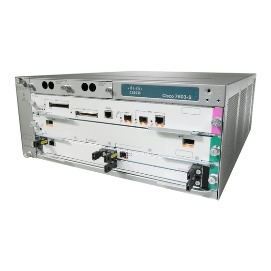
(redundant) Power supply 1 Cisco 7603-S Router The Cisco 7603-S router chassis has three horizontal slots that are numbered from top to bottom. (See Figure 1-3.) Slot 1 is reserved for the supervisor engine, which provides switching, local and remote management, and multiple GBIC uplink ports. -
Page 24: Cisco 7603-S Router
The power supplies are installed from the rear of the chassis. (See Figure 1-4.) For a detailed description of supervisor engine and route switch processor operation in a redundant configuration, refer to the Cisco 7600 Series Router Supervisor Engine and Route Switch Processor Guide. Cisco 7600 Series Router Installation Guide OL-4503-26... -
Page 25: Cisco 7604 Router
(redundant) Power supply 1 Cisco 7604 Router The Cisco 7604 router chassis has four horizontal slots that are numbered from top to bottom (See Figure 1-5). Slot 1 is reserved for the supervisor engine, which provides switching, local and remote management, and multiple GBIC uplink ports. -
Page 26: Cisco 7604 Router
• The Cisco 7604 router does not support Supervisor Engine 2. Note The Switch Fabric Module is not supported on the Cisco 7604 router. Note The Cisco 7604 router also supports: Up to three of the following hot-swappable line cards: •... -
Page 27: Cisco 7606 Router
GA GE WE R SU PP LY Cisco 7606 Router The Cisco 7606 router chassis has six horizontal slots that are numbered from top to bottom. (See Figure 1-7.) The Cisco 7606 router supports the following: Cisco 7600 Series Router Installation Guide... -
Page 28: Cisco 7606 Router
Redundant AC-input and DC-input or DC-input power supplies For a detailed description of supervisor engine operation in a redundant configuration, refer to the Cisco 7600 Series Router Supervisor Engine and Route Switch Processor Guide. The power supplies are installed from the rear of the chassis. (See Figure 1-8.) - Page 29 4 PORT OC-12 POS SM Slots 1-6 Fan assembly (top to bottom) Figure 1-8 Cisco 7606 Router—Rear View Power supply 2 (redundant) Cisc o Sys tem s Inc. Power supply 1 Cisc o Sys tem s Inc. Cisco 7600 Series Router Installation Guide OL-4503-26...
- Page 30 Chapter 1 Product Overview Cisco 7606-S Router Cisco 7606-S Router The Cisco 7606-S router chassis has six horizontal slots that are numbered from top to bottom. (See Figure 1-9.) The Cisco 7606-S router supports the following: Both supervisor engines in a single chassis must be completely identical.
-
Page 31: Cisco 7606-S Router
Fan assembly Slots 1-6 (top to bottom) Figure 1-10 Cisco 7606-S Router—Rear View Power supply 2 (redundant) Cisc o Sys tem s Inc. Power supply 1 Cisc o Sys tem s Inc. Cisco 7600 Series Router Installation Guide 1-11 OL-4503-26... -
Page 32: Cisco 7609 Router
Router (product number OSR-7609) is in the Cisco 7609 Router Installation Guide, located at this URL: http://www.cisco.com/univercd/cc/td/doc/product/core/cis7600/hardware/ osrouter/index.htm The Cisco 7609 router chassis has nine vertical slots that are numbered from right to left. (See Figure 1-11.) The Cisco 7609 Router supports the following: A Supervisor Engine 2 in slot 1 and an optional redundant Supervisor Engine 2 in slot 2. -
Page 33: Cisco 7609 Router
7609 Router (product number OSR-7609) is in the Cisco 7609 Router Installation Guide, located at this URL: http://www.cisco.com/univercd/cc/td/doc/product/core/cis7600/hardware/ osrouter/index.htm The Cisco 7609-S router chassis has nine vertical slots that are numbered from right to left. (See Figure 1-11.) Cisco 7600 Series Router Installation Guide... -
Page 34: Cisco 7609-S Router
• Redundant AC-input and DC-input ) power supplies • The Cisco 7609-S router does not support OSMs, Supervisor Engine 2, and FlexWAN (it does support Note Enhanced FlexWAN). For a detailed description of supervisor engine operation in a redundant configuration, refer to the Cisco 7600 Series Router Supervisor Engine and Route Switch Processor Guide. -
Page 35: Cisco 7613 Router
Both supervisor engines in a single chassis must be completely identical. Note For a detailed description of supervisor engine operation in a redundant configuration, refer to the Cisco 7600 Series Router Supervisor Engine and Route Switch Processor Guide. Up to 12 additional hot-swappable OSMs or Catalyst 6500 series modules •... -
Page 36: System Features
This section describes the hardware features for the Cisco 7600 series routers. For software descriptions, refer to the Cisco 7600 Series Router Supervisor Engine and Route Switch Processor Guide or the Cisco 7600 Series Internet Router IOS Software Configuration Guide. For module descriptions and installation procedures, refer to the Cisco 7600 Series Internet Router Module Installation Guide. -
Page 37: System Features
The Cisco 7600 series routers have these redundancy features: Ability to house two hot-swappable supervisor engines • Cisco 7603-S router —Ability to house two fully redundant, DC-input or DC-input, load-sharing • power supplies with power entry modules (PEMs) Cisco 7603 router—Ability to house two fully redundant, AC-input, load-sharing power supplies or •... -
Page 38: Component Hot Swapping
Cisco 7609 router, Cisco 7609-S, and Cisco 7613 router—Ability to house two fully redundant, • AC-input or DC-input, load-sharing power supplies For the Cisco 7609 router, Cisco 7613 router, and Cisco 7609-S router, you can mix one Note AC-input load-sharing power supply with one DC-input load-sharing power supply. -
Page 39: Cisco 7600 Series Router Components
(Cisco 7606-S router), and Figure 1-18 (Cisco 7609 router and Cisco 7609-S router) show the direction of airflow into and out of the router. Sensors on the supervisor engine monitor the internal air temperatures. If the air temperature exceeds a preset threshold, the environmental monitor displays warning messages. - Page 40 D- 3S HS Module air inlet ETHE RNE SERV ICES MOD ULE CLAS S 1 LASE Figure 1-15 Cisco 7604 Router Internal Airflow Module air exhaust FA N ST AT U Module air inlet Cisco 7600 Series Router Installation Guide 1-20 OL-4503-26...
- Page 41 7600- ES20 CLAS S 1 LASE -10G3 CXL ETHE RNET SERV ICES MODU LE 7600- ES20 CLAS S 1 LASE -10G3 CXL ETHE RNET SERV ICES MODU LE CLAS S 1 LASE Cisco 7600 Series Router Installation Guide 1-21 OL-4503-26...
-
Page 42: Cisco 7609-S Router
Chapter 1 Product Overview Cisco 7600 Series Router Components Figure 1-18 Cisco 7609 Router and Cisco 7609-S Router Internal Airflow Module air exhaust assemblies Power supply air exhaust Module POWE R SUPP LY 1 air inlet POWE R SUPP LY 2... -
Page 43: Cisco 7613 Router
The Cisco 7600 series routers support redundant AC-input and DC-input power supplies. This section contains information on the following topics: • Cisco 7603-S Router Power Supplies, page 1-24 Cisco 7603 Router, Cisco 7604 Router, Cisco 7606 Router, and Cisco 7606-S Power Supplies, page • 1-24 •... -
Page 44: Cisco 7603-S Router Power Supplies
The following power supply is available for the Cisco 7603-S Router 1500 W DC input (PWR-1500-DC) • Cisco 7603 Router, Cisco 7604 Router, Cisco 7606 Router, and Cisco 7606-S Power Supplies For information on installing or replacing a power supply, see the “Removing and Replacing the Power Note Supply”... - Page 45 PEM, see the “PEM” section on page 1-32. The Cisco 7604 router, the Cisco 7606 router, and the Cisco 7606-S with the 2700 W AC power supply (Figure 1-25) use an external power code directly connected to the AC power supply.
- Page 46 Figure 1-22 1900 W Power Supply Cisco 7606 Router Status LEDs Captive installation screws Figure 1-23 2700 W AC Power Supply Cisco 7604 Router P W R -A 10 0- 24 0V -1 6A 50 /6 0H IN PU T...
- Page 47 Chapter 1 Product Overview Cisco 7600 Series Router Components Figure 1-25 2700 W AC Power Supply Cisco 7606 Router and Cisco 7606-S Router P W R -2 7 0 0 -A C 10 0- 24 0V -1 6A IN PU T...
- Page 48 For information on installing or replacing a power supply, see the “Removing and Replacing the Power Supply” section on page 5-2. The Cisco 7609 router and Cisco 7613 router use the following power supplies: 4000 W AC input (WS-CAC-4000W-US1) • •...
- Page 49 2 50/60 Hz Power INPUT OUTP UT FAIL switch Status LEDs Captive installation screw Figure 1-31 2500 W DC-Input Power Supply Terminal block cover INPU T OUT PUT FAIL Captive installation screw Cisco 7600 Series Router Installation Guide 1-29 OL-4503-26...
-
Page 50: Cisco 7609-S Router Power Supplies
For information on installing or replacing a power supply, see the “Removing and Replacing the Power Note Supply” section on page 5-2. The Cisco 7609-S router use the following power supplies: 4000 W AC input (WS-CAC-4000W-US1) ) • 4000 W DC input (PWR-4000-DC) •... -
Page 51: Power Supply Cooling
Each power supply has a minimum one built-in fan. On the Cisco 7603 router, Cisco 7604 router, and the Cisco 7606 router, air enters from the right of the fan and exits through the left. On the Cisco 7609 router, the Cisco 7609-S, and the Cisco 7613 router, air enters the front of the fan (power-input end) and exits through the back;... -
Page 52: Pem
Note on page 5-112. The Cisco 7603 router, Cisco 7603-S router, and Cisco 7606 router use PEMs to connect the site power source to the power supply. Table 1-3 list the PEMs and corresponding power upplies for the Cisco 7603 and Cisco 7606 routers. - Page 53 AC-input PEMs on the Cisco 7603 Internet Router. The location Note of the PEMs is the same for AC and DC PEMs on the Cisco 7603 router, Cisco 7603-S router, and Cisco 7606 router. Cisco 7600 Series Router Installation Guide...
- Page 54 (Cisco 7603 router and Cisco 7603-S router) and Figure 1-38 (Cisco 7606 router) for power supply locations. Figure 1-37 Cisco 7603 Router and Cisco 7603-S Router—Power Supplies Power supply 2 (redundant) Power supply 1 Cisco 7600 Series Router Installation Guide...
- Page 55 Product Overview Cisco 7600 Series Router Components Figure 1-38 Cisco 7606 Router—Power Supplies Power supply 2 (redundant) Cisc o Sys tem s Inc. Power supply 1 Cisc o Sys tem s Inc. Cisco 7600 Series Router Installation Guide 1-35 OL-4503-26...
- Page 56 Chapter 1 Product Overview Cisco 7600 Series Router Components Cisco 7600 Series Router Installation Guide 1-36 OL-4503-26...
-
Page 57: Chapter 2 Preparing For Installation
Information on the Cisco 7609 Router (product number OSR-7609) is in the Cisco 7609 Router Installation Guide, located at this URL: http://www.cisco.com/univercd/cc/td/doc/product/core/cis7600/hardware/ osrouter/index.htm This chapter describes how to prepare your site for Cisco 7600 series router installation and contains these sections: Safety, page 2-2 •... -
Page 58: Safety
7600 ES+ Line Card, 4x10GE XFP with DFC 3C 7600-ES+4TG3CXL 7600 ES+ Line Card, 4x10GE XFP with DFC 3CXL 7600-SIP-200 Cisco 7600 Series SPA Interface Processor-200 7600-SIP-400 Cisco 7600 Series SPA Interface Processor-400 Cisco 7600 Series Router Installation Guide OL-4503-26... - Page 59 List of Supported Line Cards on 7600 Chasis Product Product Description 7600-SIP-600 Cisco 7600 Series SPA Interface Processor-600 7600-SSC-400 Cisco 7600 / Catalyst 6500 Services SPA Carrier Card WS-X6582-2PA Cisco7600/Catalyst6500 Enhanced FlexWAN, Fabric-enabled WS-X6548-GE-TX Catalyst 6500 48-port fabric-enabled 10/100/1000 Module WS-X6548-GE-45AF Cat6500 48-port PoE 802.3af &...
-
Page 60: Site Requirements
Site Requirements Site Requirements This section provides site power requirements for the Cisco 7600 series routers. You should verify the site power prior to installing the router. Power requirements vary for each router; ensure that you verify the site power for the type of router you are installing. - Page 61 Installing the Air Filter Assembly on a Cisco 7606 Router and the Cisco 7606-S Router (Optional), page 5-126. Installing the Air Filter Assembly on a Cisco 7609 Router and the Cisco 7609-S Router (Optional), page 5-127 Heat dissipation is an important consideration for sizing the air-conditioning requirements for an installation.
- Page 62 +2.5 VDC, +3.3 VDC, and +5 VDC to power the module. The 42 VDC is independent of the power supply’s input voltage, either 110 VAC or 220 VAC. Table 2-4 lists the power and the heat numbers for the supervisor engines. Cisco 7600 Series Router Installation Guide OL-4503-26...
- Page 63 181.65 620.33 195.32 667.03 Supervisor Engine 2 with PFC2 and MSFC2 daughter cards WS-X6K-S2U-MSFC2 3.46 145.32 181.65 620.33 195.32 667.03 Supervisor Engine 2 with PFC2 and MSFC2 daughter cards—Has 512 MB of DRAM Cisco 7600 Series Router Installation Guide OL-4503-26...
- Page 64 WS-F6K-PFC3A 2.25 94.50 118.13 403.40 127.02 433.76 Policy Feature Card 3A WS-F6K-PFC3B 1.47 61.74 77.18 263.55 82.98 283.39 Policy Feature Card 3B WS-F6K-PFC3BXL 2.57 107.94 134.93 460.77 145.08 495.45 Policy Feature Card 3BXL Cisco 7600 Series Router Installation Guide OL-4503-26...
- Page 65 Distributed Forwarding Card 3A WS-F6K-DFC3B 1.67 70.14 87.68 299.41 94.27 321.95 Distributed Forwarding Card 3B WS-F6K-DFC3BXL 2.38 99.96 124.95 426.70 134.35 458.82 Distributed Forwarding Card 3BXL WS-F6700-CFC 0.75 31.5 39.38 134.47 42.34 144.59 Centralized Forwarding Card Cisco 7600 Series Router Installation Guide OL-4503-26...
- Page 66 For all other modules that support a mandatory or optional daughter card, you must add the daughter card power to the baseboard power to get the total slot power. Cisco 7600 Series Router Installation Guide 2-10...
- Page 67 503.8 158.63 541.72 16-port 1000BASE-X Gigabit Ethernet module WS-X6416-GE-MT 2.50 105.00 131.25 448.22 141.13 481.96 8-port 1000BASE-SX Gigabit Ethernet module WS-X6516-GBIC 3.40 142.80 178.50 609.58 191.94 655.46 16-port 1000BASE-X Gigabit Ethernet module Cisco 7600 Series Router Installation Guide 2-11 OL-4503-26...
- Page 68 WS-F6K-VPWR-GE PoE daughter card WS-X6148-GE-45AF 2.65 111.30 139.13 475.11 149.60 510.87 48-port 10/100/1000 Ethernet module with WS-F6K-GE48-AF PoE daughter card WS-X6148A-GE-TX 105.0 131.25 448.22 141.13 481.96 48-port 10/100/1000 Ethernet module Cisco 7600 Series Router Installation Guide 2-12 OL-4503-26...
- Page 69 96.60 120.75 412.36 129.84 443.40 48-port 100BASE-X module WS-X6224-100FX-MT 1.90 79.8 99.75 340.65 107.26 366.3 24-port 100BASE-FX Ethernet module, MMF WS-X6324-100FX-MM 1.52 63.84 79.8 272.52 85.81 293.03 24-port 100BASE-FX Ethernet module, MMF Cisco 7600 Series Router Installation Guide 2-13 OL-4503-26...
- Page 70 1.00 42.0 52.5 179.29 56.45 192.78 48-port 10/100 Ethernet module WS-X6148A-45AF 2.57 107.94 134.93 460.77 145.08 495.45 48-port 10/100 Ethernet module WS-X6148X2-RJ-45 2.65 111.30 139.13 475.11 149.60 510.87 96-port 10/100 Ethernet module Cisco 7600 Series Router Installation Guide 2-14 OL-4503-26...
- Page 71 (BTU/HR) (Watts) (Watts) (Watts) WS-X6024-10FL-MT 1.52 63.84 79.8 272.52 85.81 293.0 24-port 10BASE-FL Ethernet module Table 2-14 lists the power and the heat numbers for the FlexWAN and the enhanced FlexWAN modules. Cisco 7600 Series Router Installation Guide 2-15 OL-4503-26...
- Page 72 105.00 131.25 448.22 141.13 481.96 Intrusion Detection System Module 2 WS-SVC-IPSEC-1 1.89 79.38 99.23 338.85 106.69 364.36 IPSec VPN Services module WS-SVC-MWAM-1 3.57 149.94 187.43 640.06 201.53 688.23 Multiprocessor WAN Application Module Cisco 7600 Series Router Installation Guide 2-16 OL-4503-26...
- Page 73 Model Number/ Module Module AC-Input Heat Diss. DC-Input Heat Diss. Module Type Current (A) Power Power (BTU/HR) Power (BTU/HR) @ 42 VDC (Watts) (Watts) (Watts) 7600-ES20-10G3CXL 8.11 1454 1563 7600-ES20-10G3C 8.11 1454 1563 Cisco 7600 Series Router Installation Guide 2-17 OL-4503-26...
- Page 74 OC-12 POS, 4-port OSM-4OC12-POS-SI+ 4.54 OC-12 POS, 4-port OSM-4OC3-POS-SI 2.42 4.70 OC-3 POS, 4-port OSM-4OC3-POS-SI+ 2.42 4.70 OC-3 POS, 4-port OSM-8OC3-POS-SI, -SL 3.57 OC-3 POS, 8-port OSM-8OC3-POS-SI+, -SL+ 3.57 OC-3 POS, 8-port Cisco 7600 Series Router Installation Guide 2-18 OL-4503-26...
- Page 75 OSM-2+4GE-WAN+ 3.76 Gigabit Ethernet WAN Services Module, 2+4-port 1. DPT = Dynamic Packet Transport 2. GBICs = Gigabit Interface Converters Table 2-19 lists the power and the heat numbers for miscellaneous modules. Cisco 7600 Series Router Installation Guide 2-19 OL-4503-26...
-
Page 76: Power Requirements
Content Switching Module Table 2-20 provides a sample calculation of power and heat dissipation for the following router configuration: • Cisco 7603 Router chassis (including AC-input power supplies) • One WS-X6K-S2U-MSFC2 supervisor engine Two 4-port OC-12 POS modules • Table 2-20... -
Page 77: Power Connection Guidelines
Table 2-19 to estimate the power requirements and heat dissipation of a Cisco 7600 series router based on a given configuration of the router. Table 2-20 provides a sample calculation. Determining power requirements might be useful for planning the power distribution system needed to support the router. - Page 78 Install only in accordance with national and local wiring regulations. Table 2-21 lists the AC-input power cord options, specifications, and Cisco product numbers for the 950 W, 1400 W, 1900 W, 3000 W, 4000 W, and the 6000 W AC-input power supplies.
- Page 79 14 feet (4.3 m) 16 A, 250 VAC Figure 2-19 America (nonlocking plug) 200–240VAC operation Japan, North CAB-AC-C6K-TWLK= 14 feet (4.3 m) 16 A, 250 VAC Figure 2-13 America (locking plug) 200–240VAC operation Cisco 7600 Series Router Installation Guide 2-23 OL-4503-26...
- Page 80 1. The 3000 W power supply operating on 110 VAC delivers 1400 W. 2. The PDU power cable is designed for users who power their switch from a PDU. The end of the cable that plugs into the Cisco 7600 series router chassis has a C19 connector; the other end of the cable that plugs into the PDU has a C20 connector.
-
Page 81: Ac Power Cord Illustrations
Length: 8 ft 2 in. (2.5 m) Connector: IEC 60320 C15 Figure 2-2 CAB-AC10A-90L-EU(=) Cordset rating: 10 A, 250 V Length: 8 ft 2 in. (2.5 m) Plug: CEE 7/7 Connector: IEC 60320 C15 Cisco 7600 Series Router Installation Guide 2-25 OL-4503-26... - Page 82 Length: 8 ft 2 in. (2.5 m) Plug: CEI 23-16/7 Connector: IEC 60320 C15 Figure 2-5 CAB-AC10A-90L-AU(=) Cordset rating: 10 A, 250 V Plug: SAA AS 3112 Length: 8 ft 2 in. (2.5 m) Connector: IEC 60320 C15 Cisco 7600 Series Router Installation Guide 2-26 OL-4503-26...
- Page 83 Length: 14 ft 0 in. (4.26 m) Plug: SAA AS 3112 Connector: IEC 60320 C19 Figure 2-8 CAB-7513ACE= Cordset rating: 16 A, 250 V Length: 14 ft 0 in. (4.26 m) Plug: CEE 7/7 Connector: IEC 60320 C19 Cisco 7600 Series Router Installation Guide 2-27 OL-4503-26...
- Page 84 Length: 14 ft 0 in. (4.26 m) Plug: IEC 309 Connector: IEC 60320 C19 Figure 2-11 CAB-7513ACI= Cordset rating: 16 A, 250 V Length: 14 ft 0 in. (4.26 m) Plug: CEI 23-16/7 Connector: IEC 60320 C19 Cisco 7600 Series Router Installation Guide 2-28 OL-4503-26...
- Page 85 Length: 14 ft 0 in. (4.26 m) Connector: IEC 60320 C19 Figure 2-13 CAB-AC-C6K-TWLK= Figure 2-14 CAB-7513ACSA= Cordset rating: 16 A, 250 V Length: 14 ft 0 in. (4.26 m) Plug: IEC 884 Connector: IEC 60320 C19 Cisco 7600 Series Router Installation Guide 2-29 OL-4503-26...
- Page 86 (1900W power supply) (1900W power supply) EN 60309 (16A, 250V) NEMA 6-20 plug (20A, 250V) NEMA L6-20 plug (20A, 250V) Europe Appliance coupler VIIG plug C19W coupler CEE (7) VII (16A) Hot EN60320/C19 (20A) Cisco 7600 Series Router Installation Guide 2-30 OL-4503-26...
- Page 87 Plug: CEE 7/7 Connector: IEC 60320 C19 Figure 2-19 CAB-AC-2500W-US1= Figure 2-20 WS-CAC-4000W-US= Hardwired to Cordset rating: 30 A, 250 V power Length: 12 ft 0 in. (3.65 m) supply Plug: NEMA L6-30 Cisco 7600 Series Router Installation Guide 2-31 OL-4503-26...
- Page 88 Length: 7 ft 0 in. (2.13 m) Plug: SEV 1011 Connector: IEC 60320 C19 Figure 2-23 CAB-AC16A-CH= Cordset rating: 16A, 250V Length: 14 ft 0 in. (4.26 m) Plug: GB16C Connector: IEC 60320-1 C19 Cisco 7600 Series Router Installation Guide 2-32 OL-4503-26...
-
Page 89: Dc-Powered Systems
60950, IEC 60950 standards. The circuit must be protected by a dedicated two-pole circuit breaker. The circuit breaker should be • sized according to the power supply input rating and local or national code requirements. Cisco 7600 Series Router Installation Guide 2-33 OL-4503-26... -
Page 90: Site Planning Checklist
Do not connect the DC-return wire to the system frame or to the system grounding equipment. Site Planning Checklist Table 2-22 lists the site planning activities that you should perform prior to installing the Cisco 7600 series router. Completing each activity helps ensure a successful router installation. Table 2-22 Site Planning Checklist Task No. - Page 91 Installation Guide, located at this URL: http://www.cisco.com/univercd/cc/td/doc/product/core/cis7600/hardware/ osrouter/index.htm This chapter describes how to install a Cisco 7600 series router in a rack. For first-time installations, perform the procedures in the following sections in the order listed: Unpacking the Router, page 3-2 •...
-
Page 92: Unpacking The Router
2-34 to verify that all site planning activities were completed. For information on installing modules, refer to the Cisco 7600 Series Router Module Installation Guide. Only trained and qualified personnel should be allowed to install, replace, or service this equipment. -
Page 93: Installation Guidelines
• The rack must have sufficient vertical clearance to insert the chassis. The chassis heights are as follows: – Cisco 7603 Router—7 inches (17.8 cm) (4 RU) – Cisco 7603-S Router—7 inches (17.8 cm) (4 RU) – Cisco 7604 router—8.7 inches (22.09 cm) (5 RU) Cisco 7606 Router—12.25 inches (31.11 cm) (7 RU) -
Page 94: Required Tools
• Installing the Shelf Brackets and Crossbar Bracket If you are installing a Cisco 7609 router, Cisco 7609-S router, or Cisco 7613 router, you must first install the shelf brackets and the crossbar bracket. To install the shelf brackets and the crossbar bracket, perform these steps:... -
Page 95: Installing The Chassis Brackets
Chapter 3 Installing the Cisco 7600 Series Router Installing the Chassis Brackets Figure 3-1 Installing the Shelf Brackets Shelf bracket Shelf bracket 12-24 x 3/4-inch 10-32 x 3/4-inch screw (6x) Figure 3-2 Attaching the Crossbar Bracket to the Shelf Brackets... - Page 96 (Telco) center flange rack-mount. You can accomplish a four-post frame mount by using two by two-post(Telco) racks placed back to back or by using a four-post enclosed rack. The Cisco 7609-S router is shipped with 19” racks. If you are installing the Cisco 7609-S router Note into a 23"...
- Page 97 Chapter 3 Installing the Cisco 7600 Series Router Installing the Chassis Brackets Figure 3-4 Brackets on Cisco 7603-S Router -48 TO PE M 1 PE -60 V 50 A MA PE M- DC -48 TO FA N -60 V 50 A MA...
- Page 98 Chapter 3 Installing the Cisco 7600 Series Router Installing the Chassis Brackets Figure 3-6 Brackets on Cisco 7606 Router WS-X6K- SUP2-2G E Switch Load CONSOLE 100% PORT MODE CONSOLE PORT 1 SUPERVI SOR2 PORT 2 PCMCIA EJECT OSM-4OC12 POS-SI 4 PORT OC-12 POS SM...
-
Page 99: Installing The Router Chassis In The Rack
Chapter 3 Installing the Cisco 7600 Series Router Installing the Router Chassis in the Rack Figure 3-8 Brackets on Cisco 7609 Router and Cisco 7609-S Router L bracket L bracket POWE R SUPP LY 1 POWE R SUPP LY 2... - Page 100 Cisco 7606 router, Figure 3-12 for the Cisco 7606-S router, and Figure 3-13 for the Cisco 7609 router, Cisco 7609-S router, and Cisco 7613 router.) Figure 3-9 Installing the Cisco 7603 Router in the Rack WS-X6K -SUP2-2 GE Switch...
- Page 101 Chapter 3 Installing the Cisco 7600 Series Router Installing the Router Chassis in the Rack Figure 3-10 Installing the Cisco 7604 Router in the Rack FA N ST AT U Figure 3-11 Installing the Cisco 7606 Router in the Rack...
- Page 102 G3CXL ETHER NET SERVI CES MODU LE CLASS 1 LASER Figure 3-13 Installing the Cisco 7609 Router, Cisco 7609-S Router, and Cisco 7613 Router in the Rack Left L bracket Right L bracket Crossbar bracket Shelf bracket Cisco 7600 Series Router Installation Guide...
-
Page 103: Installing The Stabilizer Kit (Cisco 7609 Router, Cisco 7609-S, And Cisco 7613 Router Only)
The stabilizer kit is included only in the accessory kits for the Cisco 7609 Router and Cisco 7613 Router. Note If you are not installing the Cisco 7609 router, Cisco 7609-S router, or Cisco 7613 Router in a rack, you must install stabilizer brackets to the bottom of the chassis. The stabilizer brackets reduce the possibility that the freestanding chassis will tip over. - Page 104 Chapter 3 Installing the Cisco 7600 Series Router Installing the Stabilizer Kit (Cisco 7609 Router, Cisco 7609-S, and Cisco 7613 Router Only) Open the stabilizer kit package and use the kit contents list in Table 3-1 to verify that all parts are included.
-
Page 105: Installing The Cable Management System (Cisco 7609 Router And Cisco 7609-S Router Only)
Lower the chassis so that it rests on both stabilizer brackets. Note If you are not rack-mounting the Cisco 7613 Router and you want to install the cable guide assemblies, you must obtain ten 12x24 or 10x32 nuts. Use the screws supplied in the accessory kit and the nuts you obtained to attach the cable guide assembly to the L bracket. - Page 106 Cisco 7609-S router(CABLETRAY-09S=). Do note that the extended and the standard cable guides are included in the CABLETRAY-09= that is shipped with Cisco 7609 routers, and only the extended cable guide is included in the CABLETRAY-09S= shipped with Cisco 7609-S routers.
-
Page 107: Replacing The Cable Guide
Chapter 3 Installing the Cisco 7600 Series Router Installing the Cable Management System (Cisco 7609 Router and Cisco 7609-S Router Only) Loosen the two captive installation screws on the front panel. (See Figure 3-18.) Step 3 Figure 3-17 Removing the Front Panel... - Page 108 Chapter 3 Installing the Cisco 7600 Series Router Installing the Cable Management System (Cisco 7609 Router and Cisco 7609-S Router Only) Figure 3-18 Removing the Front Panel STATU S Captive installation screws Remove the front panel and set it aside.
-
Page 109: System Ground Connection
Captive installation screws System Ground Connection This section describes how to connect a system (earth) ground to the Cisco 7600 series router. You must connect the system ground on both AC- and DC-powered systems to an earth ground if Foreign... -
Page 110: Required Tools And Equipment
5-80. On the Cisco 7603 router, Cisco 7603-S router, Cisco 7604 router, Cisco 7606 router, Cisco 7606-S router, and Cisco 7613 router, two threaded M4 holes are provided on the chassis frame to attach the ground cable. (See Figure 3-21... - Page 111 OSM-4OC 12 POS-SI 4 PORT OC-12 POS SM OSM-4OC 12 POS-SI 4 PORT OC-12 POS SM The Cisco 7609-S router uses the 4AWG grounding lug and M6 hex-head screws with locking washers Note provided in kit 69-1713-02. Figure 3-22 Cisco 7604 Router—System Ground Location...
- Page 112 Chapter 3 Installing the Cisco 7600 Series Router System Ground Connection Figure 3-23 Cisco 7606-S Router—System Ground Location System ground connector Grounding System ground Wire connector 7600- ES20 FA N -10G3 CXL ST AT US Cis co 760 ETHE RNET...
- Page 113 Note itself provides the system ground. You must use an industry standard 2-hole compression lug for the power supply ground terminal. For information, see Installing a PWR-4000-DC Power Supply in a Cisco 7613 Router, page 5-91. Cisco 7600 Series Router Installation Guide...
-
Page 114: Connecting The System Ground
Grounding lug System ground connector The system ground connection with the PWR-4000-DC power supply in a Cisco 7609 router and a Cisco Note 7609-S router is provided by the PWR-4000-DC power supply ground. Additionally, you can connect a system (earth) ground. For information, see... -
Page 115: Installing The Power Supplies In The Router Chassis
Depending on the modules you have installed in your chassis, you will have different styles of connectors to attach. Refer to the Cisco 7600 Series Router Module Installation Guide for additional module information. Note Cisco 7600 Series Router Installation Guide... -
Page 116: Connecting The Supervisor Engine Console Port
Monitor network statistics and errors • Configure SNMP agent parameters Download software updates to the Cisco 7600 series router or distribute software images residing in • Flash memory to attached devices The console port, located on the front panel of the supervisor engine, is shown in Figure 3-26. -
Page 117: Connecting The Supervisor Engine Uplink Ports
Chapter 3 Installing the Cisco 7600 Series Router Attaching the Interface Cables 9600 baud • 8 data bits • No parity • 2 stop bits • To connect a terminal using a Catalyst 5000 family Supervisor Engine III console cable, perform these... -
Page 118: Connecting To The Interface Ports
Chapter 3 Installing the Cisco 7600 Series Router Attaching the Interface Cables Remove the plugs from the Gigabit Interface Converter (GBIC) optical bores; store them for future use. Step 1 Remove the plugs from the SC-type connector on the fiber-optic cable. Insert the connector into the Step 2 GBIC. - Page 119 Chapter 3 Installing the Cisco 7600 Series Router Attaching the Interface Cables Figure 3-28 SC-Type Fiber-Optic Connector Figure 3-29 LC Fiber-Optic Connector Figure 3-30 MT-RJ Fiber-Optic Connector Figure 3-31 Mini-SMB Cable Connector Figure 3-32 RJ-45 Connectors Cisco 7600 Series Router Installation Guide...
-
Page 120: Verifying Router Chassis Installation
Step 2 any loose captive installation screws. On the Cisco 7603 Router and Cisco 7606 Router, PEM 1 connects the site power source to power Note supply 1; PEM 2 connects the site power source to power supply 2. If there is only one PEM and one power supply installed in the chassis, verify that they are in the correct bays before powering up the system. -
Page 121: Chapter 4 Troubleshooting
C H A P T E R Troubleshooting This chapter describes how to troubleshoot the Cisco 7600 series router hardware installation and contains these sections: Getting Started, page 4-1 • Problem Solving to the System Component Level, page 4-2 •... -
Page 122: Problem Solving To The System Component Level
Power supply—Includes the power supplies and power supply fans. • Power entry module (PEM)—On the Cisco 7603 Router and Cisco 7606 Router, there is one PEM • for each power supply. The PEM connects the site source to the power supply. -
Page 123: Troubleshooting The Power Supply
For a complete description of the supervisor engine LEDs, refer to the Cisco 7600 Series Internet Router Module Installation Guide. Verify that the STATUS LEDs on the supervisor engine and on each module are green when the Step 3 supervisor engine completes initialization. - Page 124 Once the power is enabled, measure the voltage at the input terminal block. Verify that the DC voltage between the negative and positive terminal is between –37 VDC and –56 VDC. The acceptable range for AC power supply is 110V-230V. Cisco 7600 Series Router Installation Guide OL-4503-26...
- Page 125 The cooling system has a fully redundant architecture that allows the chassis to continue operating with a single-fault failure (such as a single fan or fan tray failure). The chassis cooling system includes: • One or Two fan trays (depending upon the chassis). Cisco 7600 Series Router Installation Guide OL-4503-26...
-
Page 126: Troubleshooting The Fan Assembly
There are no installation adjustments to make if the fan assembly does not function properly at the initial startup. Troubleshooting An Old Fan Module Table 4-6 lists the solutions to force an old fan module to work in single RPs only. Cisco 7600 Series Router Installation Guide OL-4503-26... -
Page 127: Troubleshooting The Fan Assembly
IOS Software Configuration Guide, the Cisco 7600 Series Internet Router IOS Command Reference or the Cisco 7600 Series Internet Router IOS Command Reference publications to configure or enable the interfaces. After the system reinitializes the interfaces, the status LED on the module should be green. -
Page 128: Contacting Customer Service
Type of software and release number Maintenance agreement or warranty information • Brief description of the problem • Brief explanation of the steps you have already taken to isolate and resolve the problem • Cisco 7600 Series Router Installation Guide OL-4503-26... -
Page 129: Preventing Electrostatic Discharge Damage
Installing the Air Filter Assembly on a Cisco 7606 Router and the Cisco 7606-S Router (Optional), • page 5-126 Replacing the Air Filter on a Cisco 7609 Router and the Cisco 7609-S Router (Optional), page 5-131 • Installing the Thermistor Module on a Cisco 7606-S Router, page 5-133 •... -
Page 130: Removing And Replacing The Power Supply
1 and 10 megohm (Mohm). Removing and Replacing the Power Supply This section describes how to remove and install power supplies for the Cisco 7600 series routers. Note In systems with redundant power supplies, you can replace the faulty supply while the system is operating. -
Page 131: Removing An Ac-Input Power Supply
Figure 5-1 shows the location of the AC-input PEMs on the Cisco 7603 router. The location of the PEMs is the same for AC and DC PEMs on the Cisco 7603 router and Cisco 7606 router. Note If you are planning on installing a PWR-2700-AC power supply in a Cisco 7606 router, you must remove any PEMs and install a blank PEM filler plate. - Page 132 Loosen the captive installation screws on the power supply. (See Figure 5-2 for the Cisco 7603 router, Step 4 Figure 5-3 for the Cisco 7604 router, Cisco 7606 router, andCisco 7606-S router, Figure 5-4 for the Cisco 7609 router, Cisco 7609-S router, and Cisco 7613 router.) Figure 5-2 Cisco 7603 Router—Power Supply Captive Installation Screws...
- Page 133 Captive installation screw Cisco 7603 router, Cisco 7609 router, Cisco 7609-S, and Cisco 7613 router—Grasp the power supply Step 5 handle with one hand and slide the power supply part of the way out of the chassis. Place your other hand...
- Page 134 Chapter 5 Removal and Replacement Procedures Removing and Replacing the Power Supply Figure 5-5 Cisco 7603 Router—Handling an AC-Input Power Supply Power Supply 2 (redundant) Power Supply 1 Cisco 7600 Series Router Installation Guide OL-4503-26...
- Page 135 Chapter 5 Removal and Replacement Procedures Removing and Replacing the Power Supply Figure 5-6 Cisco 7609 Router, Cisco 7609-S, and Cisco 7613 Router— Handling an AC-Input Power Supply INPUT OUTPUT FAIL INPUT OUTPUT FAIL INPUT OUTPU T FAIL Cisco 7600 Series Router Installation Guide...
-
Page 136: Installing An Ac-Input Power Supply
Figure 5-7 Cisco 7604, Cisco 7606, Cisco 7606-S Routers—Handling an AC-Input Power Supply If the power supply bay is to remain empty, install a blank power supply filler plate (Cisco Step 6 part number 800-16727-01 for the Cisco 7603 router, 800-19193-01 for the Cisco 7606 router, 800-28533-01 for the Cisco 7606-S router, and 700-03104-01 for the Cisco 7609 and Cisco 7613 routers) over the opening and secure it with the captive installation screws. -
Page 137: Identifying Startup Problems
5-7. Slide the power supply into the power supply bay. Make sure that the power supply is fully seated in the bay. If you are installing a PWR-2700-AC power supply in a Cisco 7606 router, you must remove any Note preinstalled PEMs. - Page 138 • Removing a WS-CDC-2500W Power Supply from a Cisco 7613 Router, page 5-26 • Removing a PWR-4000-DC Power Supply from a Cisco 7609 Router or a Cisco 7609-S Router, page • 5-28 Removing a PWR-6000-DC Power Supply from a Cisco 7609 or a Cisco 7609-S Router, page 5-31 •...
- Page 139 (redundant) Power Supply 1 If the power supply bay is to remain empty, install a blank power supply filler plate (Cisco Step 4 part number 800-16727-01 for the Cisco 7603 router) over the opening and secure it with the captive installation screws.
- Page 140 Loosen the captive installation screws on the power supply (Figure 5-12). Step 2 Figure 5-12 Cisco 7603-S Router—Power Supply Captive Installation Screws P W R - 1 5 0 0 - D C Status LEDs A LL FA S TE N E...
- Page 141 Power Supply 1 If the power supply bay is to remain empty, install a blank power supply filler plate (Cisco part number Step 4 800-28728-01 for the Cisco 7603-S router) over the opening and secure it with the captive installation screws.
- Page 142 Loosen the captive installation screws on the power supply (Figure 5-14). Step 6 Use both hands to install and remove power supplies. Each PWR-2700-DC DC-input power supply Caution weighs 13.4 pounds (6.1 kg). Cisco 7600 Series Router Installation Guide 5-14 OL-4503-26...
- Page 143 Verify that power is off to the DC circuit connected to the DC PEM for the power supply you are removing (Figure 5-17). The location of the PEMs is the same for AC and DC PEMs on the Cisco 7603 and Cisco 7606 routers. Cisco 7600 Series Router Installation Guide...
- Page 144 Loosen the captive installation screws on the power supply (Figure 5-18). Step 2 Figure 5-18 Cisco 7606 Router—Power Supply Captive Installation Screws Status LEDs Captive installation screws Grasp both power supply handles, as shown in Figure 5-19, and slide the power supply completely out Step 3 of the chassis.
- Page 145 Figure 5-19 Cisco 7606 Router—Handling an DC-Input Power Supply If the power supply bay is to remain empty, install a blank power supply filler plate (Cisco part number Step 4 800-19193-01 for the Cisco 7606 router) over the opening and secure it with the captive installation screws.
- Page 146 Loosen the captive installation screws on the power supply (Figure 5-20). Step 6 Use both hands to install and remove power supplies. Each PWR-2700-DC DC-input power supply Caution weighs 14.1 pounds (6.4 kg). Cisco 7600 Series Router Installation Guide 5-18 OL-4503-26...
- Page 147 GA GE PO W ER SU PP LY If the power supply bay is to remain empty, install a blank power supply filler plate (Cisco part number Note 700-03104-01) over the opening, and secure it with the captive installation screws.
- Page 148 Loosen the captive installation screws on the power supply (Figure 5-22). Step 6 Use both hands to install and remove power supplies. Each PWR-2700-DC DC-input power supply Caution weighs 14.1 pounds (6.4 kg). Cisco 7600 Series Router Installation Guide 5-20 OL-4503-26...
- Page 149 GA GE PO W ER SU PP LY If the power supply bay is to remain empty, install a blank power supply filler plate (Cisco part number Note 800-28533-01) over the opening, and secure it with the captive installation screws...
- Page 150 Loosen the captive installation screws on the power supply (Figure 5-22). Step 6 Caution Use both hands to install and remove power supplies. Each PWR-2700-DC DC-input power supply weighs 14.1 pounds (6.4 kg). Cisco 7600 Series Router Installation Guide 5-22 OL-4503-26...
- Page 151 FA N OU TP UT FA IL If the power supply bay is to remain empty, install a blank power supply filler plate (Cisco part number Note 800-28533-01) over the opening, and secure it with the captive installation screws Removing a WS-CDC-2500W Power Supply from a Cisco 7609 Router Warning Before performing any of the following procedures, ensure that power is removed from the DC circuit.
- Page 152 Disconnect the DC-input wires from the terminal block (Figure 5-27) in this order: Step 4 Positive (+) • • Negative (-) • Ground When installing the unit, the ground connection must always be made first and disconnected last. Warning Cisco 7600 Series Router Installation Guide 5-24 OL-4503-26...
- Page 153 Place your other hand underneath the power supply, as shown in Figure 5-28, and slide the power supply completely out of the chassis. Figure 5-28 Handling a DC-Input Power Supply INPU T OUT PUT FAIL Cisco 7600 Series Router Installation Guide 5-25 OL-4503-26...
- Page 154 Removal and Replacement Procedures Removing and Replacing the Power Supply If the power supply bay is to remain empty, install a blank power supply filler plate (Cisco part number Step 7 700-03104-01) over the opening, and secure it with the captive installation screws.
- Page 155 Grasp the power supply handle with one hand and slide the power supply part of the way out of the Step 6 chassis. Place your other hand underneath the power supply, as shown in Figure 5-31, and slide the power supply completely out of the chassis. Cisco 7600 Series Router Installation Guide 5-27 OL-4503-26...
- Page 156 INPU T OUT PUT FAIL If the power supply bay is to remain empty, install a blank power supply filler plate (Cisco part number Step 7 700-03104-01) over the opening, and secure it with the captive installation screws. Removing a PWR-4000-DC Power Supply from a Cisco 7609 Router or a Cisco 7609-S Router Before performing any of the following procedures, ensure that power is removed from the DC circuit.
- Page 157 Some configurations require cable tie-wraps. For more information, refer to Installing a PWR-4000-DC Power Supply in a Cisco 7609 Router or a Cisco 7609-S Router, page 5-70. Remove the two screws securing the left inner terminal block cover and one screw securing the right Step 5 inner terminal block cover.
- Page 158 Loosen the captive installation screw on the power supply (Figure 5-33). Use both hands to install and remove power supplies. Each DC-input power supply weighs between 22 Caution pounds (9.9 kg) and 33 pounds (15 kg). Cisco 7600 Series Router Installation Guide 5-30 OL-4503-26...
- Page 159 INPU T OK OUTP UT FAIL If the power supply bay is to remain empty, install a blank power supply filler plate (Cisco part number Step 11 700-03104-01) over the opening, and secure it with the captive installation screws. Removing a PWR-6000-DC Power Supply from a Cisco 7609 or a Cisco 7609-S Router Before performing any of the following procedures, ensure that power is removed from the DC circuit.
- Page 160 Remove the two A4 screws securing the terminal block cover, and remove the cover from the power Step 3 supply (Figure 5-35). Cut any cable tie-wraps being careful not to cut the DC-input wires. Step 4 Cisco 7600 Series Router Installation Guide 5-32 OL-4503-26...
- Page 161 Note redundant configurations. Some configurations require cable tie-wraps, depending on available DC input pairs. For more information, refer to Installing a PWR-6000-DC Power Supply in a Cisco 7609 or a Cisco 7609-S Router, page 5-80. Disconnect the DC-input wires from the terminal block in this order:...
- Page 162 Grasp the power supply handle with one hand and slide the power supply part of the way out of the chassis. Place your other hand underneath the power supply, as shown in Figure 5-38 (without IPM) and Figure 5-39 (with IPM), and slide the power supply completely out of the chassis. Cisco 7600 Series Router Installation Guide 5-34 OL-4503-26...
- Page 163 OU TPU FAI L If the power supply bay is to remain empty, install a blank power supply filler plate (Cisco part number 700-03104-01) over the opening, and secure it with the captive installation screws. Removing a PWR-4000-DC Power Supply from a Cisco 7613 Router Before performing any of the following procedures, ensure that power is removed from the DC circuit.
- Page 164 Note configurations. Some configurations require cable tie-wraps. For more information, refer to Installing a PWR-4000-DC Power Supply in a Cisco 7613 Router, page 5-91. Step 5 Remove the two screws securing the left inner terminal block cover and one screw securing the right inner terminal block cover.
- Page 165 FAIL ( ) Ground Captive installation screw Figure 5-41 shows a 4000 W configuration that requires cable tie-wraps. Note Loosen the captive installation screw on the power supply (Figure 5-41). Step 9 Cisco 7600 Series Router Installation Guide 5-37 OL-4503-26...
- Page 166 INPU T OK OUTP UT FAIL If the power supply bay is to remain empty, install a blank power supply filler plate (Cisco part number Step 11 700-03104-01) over the opening, and secure it with the captive installation screws. Removing a PWR-6000-DC Power Supply from a Cisco 7613 Router Before performing any of the following procedures, ensure that power is removed from the DC circuit.
- Page 167 IPM. To use this option, do not perform steps 3 through 6 and go to step 7. Step 3 Remove the two A4 screws securing the terminal block cover, and remove the cover from the power supply (Figure 5-43). Cisco 7600 Series Router Installation Guide 5-39 OL-4503-26...
- Page 168 Note redundant configurations. Some configurations require cable tie-wraps, depending on available DC input pairs. For more information, refer to Installing a PWR-6000-DC Power Supply in a Cisco 7609 or a Cisco 7609-S Router, page 5-80. Disconnect the DC-input wires from the terminal block in this order:...
- Page 169 Step 10 chassis. Place your other hand underneath the power supply, as shown in Figure 5-46 (without IPM) and Figure 5-47 (with IPM), and slide the power supply completely out of the chassis. Cisco 7600 Series Router Installation Guide 5-41 OL-4503-26...
-
Page 170: Installing Dc-Input Power Supplies
INP UT OU TPU FAI L If the power supply bay is to remain empty, install a blank power supply filler plate (Cisco part number 700-03104-01) over the opening, and secure it with the captive installation screws. Installing DC-Input Power Supplies... - Page 171 • Installing a WS-CDC-2500W Power Supply in a Cisco 7613 Router, page 5-67 • Installing a PWR-4000-DC Power Supply in a Cisco 7609 Router or a Cisco 7609-S Router, page • 5-70 Installing a PWR-6000-DC Power Supply in a Cisco 7609 or a Cisco 7609-S Router, page 5-80 •...
- Page 172 Verify power supply operation by checking that the power supply front panel LEDs are in the following Step 7 states: INPUT OK LED is green • FAN OK LED is green • OUTPUT FAIL LED is not lit • Cisco 7600 Series Router Installation Guide 5-44 OL-4503-26...
- Page 173 If the LEDs indicate a power problem, see the “Identifying Startup Problems” section on page 4-2. Installing a PWR-1500-DC Power Supply in a Cisco 7603-S Router Before performing any of the following procedures, ensure that power is removed from the DC circuit. Warning...
- Page 174 Step 1 Power supply ground is required. Note The system ground connection with the PWR-2700-DC/4 power supply in a Cisco 7604 router is provided by the PWR-2700-DC/4 power supply ground. Additionally, you can connect a system (earth) ground. Cisco 7600 Series Router Installation Guide...
- Page 175 Chapter 5 Removal and Replacement Procedures Removing and Replacing the Power Supply When using a PWR-2700-DC/4 power supply in a Cisco 7604 router, you must always connect Note the PWR-2700-DC/4 power supply ground. For redundant power supplies, you must connect the PWR-2700-DC/4 power supply ground for Note both power supplies.
- Page 176 For multiple DC input power supply, each DC input must be protected by dedicated circuit breaker or Note fuse. The circuit breaker or fuse should be sized according to the power supply input rating and local or national electrical code requirements. Cisco 7600 Series Router Installation Guide 5-48 OL-4503-26...
- Page 177 Use only copper wire. The maximum width of a lug is 0.600 inch (15.2 mm). For 2700 W power supplies, use fine-stranded copper conductors rated for 45-degrees Celsius Note for North American installations. Cisco 7600 Series Router Installation Guide 5-49 OL-4503-26...
- Page 178 INPUT OK LED is green • FAN OK LED is green • OUTPUT FAIL LED is not lit • If the LEDs indicate a power problem, see the “Identifying Startup Problems” section on page 4-2. Cisco 7600 Series Router Installation Guide 5-50 OL-4503-26...
- Page 179 G E D E R S U P P LY Installing a PWR-1900-DC Power Supply in a Cisco 7606 Router Before performing any of the following procedures, ensure that power is removed from the DC circuit. Warning Follow these steps to install a DC-input power supply: Step 1 Ensure that the system (earth) ground connection has been made.
- Page 180 Verify that all connections to the DC PEM are secure. Step 4 Remove the tape from the circuit breaker switch handle, and restore power by moving the circuit breaker Step 5 switch handle to the On (|) position. Cisco 7600 Series Router Installation Guide 5-52 OL-4503-26...
- Page 181 Before performing any of the following procedures, ensure that power is removed from the DC circuit. Warning If you are installing a PWR-2700-DC power supply in a Cisco 7606 router, you must remove any Note preinstalled PEMs. You must also install a blank PEM filler plate for each power supply you are installing.
- Page 182 P P LY Captive installation screws Note This illustration shows the terminal block barriers and terminal block guards attached. Warning Power supply captive installation screws must be tight to ensure protective grounding continuity. Cisco 7600 Series Router Installation Guide 5-54 OL-4503-26...
- Page 183 Attach the appropriate lugs to the DC-input wires. The maximum width of a lug is 0.600 inch (15.2 mm). Step 6 The wire should be sized according to local and national installation requirements. Use only copper wire. Cisco 7600 Series Router Installation Guide 5-55 OL-4503-26...
- Page 184 INPUT OK LED is green • • FAN OK LED is green • OUTPUT FAIL LED is not lit If the LEDs indicate a power problem, see the “Identifying Startup Problems” section on page 4-2. Cisco 7600 Series Router Installation Guide 5-56 OL-4503-26...
- Page 185 G E D E R S U P P LY Installing a PWR-2700-DC Power Supply in a Cisco 7606-S Router Warning Before performing any of the following procedures, ensure that power is removed from the DC circuit. Follow these steps to install a DC-input power supply: Ensure that the system (earth) ground connection has been made.
- Page 186 P P LY Captive installation screws Note This illustration shows the terminal block barriers and terminal block guards attached. Warning Power supply captive installation screws must be tight to ensure protective grounding continuity. Cisco 7600 Series Router Installation Guide 5-58 OL-4503-26...
- Page 187 Attach the appropriate lugs to the DC-input wires. The maximum width of a lug is 0.600 inch (15.2 mm). Step 6 The wire should be sized according to local and national installation requirements. Use only copper wire. Cisco 7600 Series Router Installation Guide 5-59 OL-4503-26...
- Page 188 INPUT OK LED is green • • FAN OK LED is green • OUTPUT FAIL LED is not lit If the LEDs indicate a power problem, see the “Identifying Startup Problems” section on page 4-2. Cisco 7600 Series Router Installation Guide 5-60 OL-4503-26...
- Page 189 E R S U P P LY xxxx Installing a PWR-4500-DC Power Supply in a Cisco 7606-S Router There are different power supply configurations available for the Cisco 7606-S router. See the appendix, Note Cisco 7606-S DC Power Supply Configurations, for more information.
- Page 190 5 0 0 -D C screws IN PU T1 IN PU T2 FA N O UT PU FA IL This illustration shows the terminal block barriers and terminal block guards attached. Note Cisco 7600 Series Router Installation Guide 5-62 OL-4503-26...
- Page 191 Power supply captive installation screws must be tight to ensure protective grounding continuity. Remove the four screws securing the terminal block cover, and slide the cover off of the terminal block Step 5 (Figure 5-66). Cisco 7600 Series Router Installation Guide 5-63 OL-4503-26...
- Page 192 INPUT OK LED is green • FAN OK LED is green • • OUTPUT FAIL LED is not lit If the LEDs indicate a power problem, see the “Identifying Startup Problems” section on page 4-2. Cisco 7600 Series Router Installation Guide 5-64 OL-4503-26...
- Page 193 Removal and Replacement Procedures Removing and Replacing the Power Supply xxxx Installing a WS-CDC-2500W Power Supply in a Cisco 7609 Router Warning Before performing any of the following procedures, ensure that power is removed from the DC circuit. Follow these steps to install a DC-input power supply: Ensure that the system (earth) ground connection has been made.
- Page 194 Connect the DC-input wires to the 2500 W power supply terminal block (Figure 5-71) in this order: Step 7 Ground • Negative (-) • • Positive (+) Warning When installing the unit, the ground connection must always be made first and disconnected last. Cisco 7600 Series Router Installation Guide 5-66 OL-4503-26...
- Page 195 If the LEDs indicate a power problem, see the “Identifying Startup Problems” section on page 4-2. Installing a WS-CDC-2500W Power Supply in a Cisco 7613 Router Before performing any of the following procedures, ensure that power is removed from the DC circuit. Warning...
- Page 196 Slide the power supply into the power supply bay. Make sure that the power supply is fully seated in the (Figure 5-72). Figure 5-72 Handling a DC-Input Power Supply INPU T OUT PUT FAIL Tighten the power supply captive installation screws (Figure 5-73). Step 4 Cisco 7600 Series Router Installation Guide 5-68 OL-4503-26...
- Page 197 Connect the DC-input wires to the 2500 W power supply terminal block (Figure 5-74) in this order: Step 7 Ground • Negative (-) • • Positive (+) Warning When installing the unit, the ground connection must always be made first and disconnected last. Cisco 7600 Series Router Installation Guide 5-69 OL-4503-26...
- Page 198 If the LEDs indicate a power problem, see the “Identifying Startup Problems” section on page 4-2. Installing a PWR-4000-DC Power Supply in a Cisco 7609 Router or a Cisco 7609-S Router Before performing any of the following procedures, ensure that power is removed from the DC circuit. Warning...
- Page 199 Power supply ground is required. Step 1 Note The system ground connection with the PWR-4000-DC power supply in a Cisco 7609 router is provided by the PWR-4000-DC power supply ground. Additionally, you can connect a system (earth) ground. Note When using a PWR-4000-DC power supply in a Cisco 7609 router, you must always connect the PWR-4000-DC power supply ground.
- Page 200 (Figure 5-75). Figure 5-75 Handling a DC-Input Power Supply VE-1 VE-3 VE-1 VE-3 VE-2 VE-2 INPU T OK OUTP UT FAIL Step 4 Tighten the power supply captive installation screw (Figure 5-76). Cisco 7600 Series Router Installation Guide 5-72 OL-4503-26...
- Page 201 Attach the appropriate lugs to the DC-input wires and ground wire. The wires should be sized according Step 7 to local and national installation requirements. Use only copper wire. Cisco 7600 Series Router Installation Guide 5-73 OL-4503-26...
- Page 202 (+)/negative (-) terminal pairs in any sequence. Select 4000 W by wiring all three terminals. The Cisco IOS software detects the wired inputs and sets the proper system power. If you are wiring for 2700 W for a single power supply, proceed to Step 9; if you are wiring 2700 W for Note a redundant power supply, proceed to Step 9 and then Step 11.
- Page 203 Pull the tab until the cover is secured around the power cabling trim and discard excess tab plastic. From the left side of the power supply, connect the ground wire to the ground (Figure 5-78). Cisco 7600 Series Router Installation Guide 5-75 OL-4503-26...
- Page 204 The protective end flap on the plastic cover is opposite the wire entry area. The protective end flap must fold down and cover the open side of the terminal (opposite side from wire entry). Cisco 7600 Series Router Installation Guide 5-76 OL-4503-26...
- Page 205 Using the cable tie provided, place the cable tie through the slot at the top of the right terminal block cover and secure the wiring to the left terminal block. Secure outer block cover. Cisco 7600 Series Router Installation Guide 5-77 OL-4503-26...
- Page 206 Recommended torque strength is 20 inch-pounds. Over tightening the terminal nuts can break the terminal block (Maximum torque: 36 inch-pounds). From the right side of the power supply, connect the DC-input wires to TB1 (Figure 5-80) in this order: Negative (-) Cisco 7600 Series Router Installation Guide 5-78 OL-4503-26...
- Page 207 INPUT OK LED is green • FAN OK LED is green • OUTPUT FAIL LED is not lit • If the LEDs indicate a power problem, see the “Identifying Startup Problems” section on page 4-2. Cisco 7600 Series Router Installation Guide 5-79 OL-4503-26...
- Page 208 Follow these steps to install a DC-input power supply: The PWR-6000-DC power supply ground provides the system ground connection when the Note PWR-6000-DC power supply is installed in a Cisco 7609-S router. Install the ground as described in this procedure. Note For redundant power supplies, you must connect the PWR-6000-DC power supply ground for both power supplies.
- Page 209 5-81). Figure 5-81 Handling a DC-Input Power Supply CIS CO SY ST EM S, INC INP UT OU TPU FAI L Tighten the power supply captive installation screw (Figure 5-82). Step 3 Cisco 7600 Series Router Installation Guide 5-81 OL-4503-26...
- Page 210 (Figure 5-82). Attach the appropriate lugs to the DC-input wires and ground wire. The wires should be sized according Step 5 to local and national installation requirements. Use only copper wire. Cisco 7600 Series Router Installation Guide 5-82 OL-4503-26...
- Page 211 2800 W by wiring any two positive (+)/negative (-) terminal pairs in any sequence. Select 4500 W by wiring any three positive (+)/negative (-) terminal pairs in any sequence. Select 6000 W by wiring all four terminals. The Cisco IOS software detects the wired inputs and sets the proper system power.
- Page 212 Secure outer block cover. Step 7 Wire for 4500 W (left side of power supply bay) as follows: From the left side of the power supply, connect the ground wire to the ground (Figure 5-84). Cisco 7600 Series Router Installation Guide 5-84 OL-4503-26...
- Page 213 Secure outer block cover. Wire for 6000 W (left side of power supply bay) as follows: Step 8 From the left side of the power supply, connect the ground wire to the ground (Figure 5-85). Cisco 7600 Series Router Installation Guide 5-85 OL-4503-26...
- Page 214 (Maximum torque: 36 inch-pounds). Wire for 2800 W (right side of power supply bay) as follows: Step 9 From the right side of the power supply, connect the ground wire to the ground (Figure 5-86). Cisco 7600 Series Router Installation Guide 5-86 OL-4503-26...
- Page 215 6000W DC-input power supply must come from the same battery system (A feed); both pairs of input wires for the other 6000W DC-input power supply must come from another battery system (B feed). Cisco 7600 Series Router Installation Guide 5-87 OL-4503-26...
- Page 216 When you tighten the terminal nuts, make sure they are snug. Do not over tighten them. Recommended torque strength is 20 inch-pounds. Over tightening the terminal nuts can break the terminal block (Maximum torque: 36 inch-pounds). Secure outer block cover. Cisco 7600 Series Router Installation Guide 5-88 OL-4503-26...
- Page 217 ( ) Ground installation screw From the right side of the power supply, connect each of the DC-input wires to the terminal block (Figure 5-82 Figure 5-88) in this order: Negative (-) Positive (+) Cisco 7600 Series Router Installation Guide 5-89 OL-4503-26...
- Page 218 Use the power switch to turn the power supply on. Step 14 Verify power supply operation by checking that the power supply front panel LEDs are in the following Step 15 states: Cisco 7600 Series Router Installation Guide 5-90 OL-4503-26...
- Page 219 Note The PWR-4000-DC power supply ground provides the system ground connection when the PWR-4000-DC power supply is installed in a Cisco 7613 router. Install the ground as described in this procedure. For redundant power supplies, you must connect the PWR-4000-DC power supply ground for both Note power supplies.
- Page 220 (Figure 5-90). Figure 5-90 Handling a DC-Input Power Supply VE-1 VE-3 VE-1 VE-3 VE-2 VE-2 INPU T OK OUTP UT FAIL Tighten the power supply captive installation screw (Figure 5-91). Step 3 Cisco 7600 Series Router Installation Guide 5-92 OL-4503-26...
- Page 221 Attach the appropriate lugs to the DC-input wires and ground wire. The wires should be sized according Step 6 to local and national installation requirements. Use only copper wire. Cisco 7600 Series Router Installation Guide 5-93 OL-4503-26...
- Page 222 (+)/negative (-) terminal pairs in any sequence. Select 4000 W by wiring all three terminals. The Cisco IOS software detects the wired inputs and sets the proper system power. If you are wiring for 2700 W for a single power supply, proceed to Step 8; if you are wiring 2700 W for Note a redundant power supply, proceed to Step 8 and then Step 10.
- Page 223 Pull the tab until the cover is secured around the power cabling trim and discard excess tab plastic. From the left side of the power supply, connect the ground wire to the ground (Figure 5-93). Cisco 7600 Series Router Installation Guide 5-95 OL-4503-26...
- Page 224 Using the cable tie provided, place the cable tie through the slot at the top of the left terminal block cover and secure the wiring going to TB2. Place and secure left and right inner terminal block cover. Secure outer block cover. Cisco 7600 Series Router Installation Guide 5-96 OL-4503-26...
- Page 225 When you tighten the terminal nuts, make sure they are snug. Do not over tighten them. Recommended torque strength is 20 inch-pounds. Over tightening the terminal nuts can break the terminal block (Maximum torque: 36 inch-pounds). Place and secure left and right inner terminal block cover. Cisco 7600 Series Router Installation Guide 5-97 OL-4503-26...
- Page 226 5-95) in this order: Negative (-) Positive (+) From the right side of the power supply, connect the DC-input wires to TB1 (Figure 5-91 Figure 5-95) in this order: Negative (-) Positive (+) Cisco 7600 Series Router Installation Guide 5-98 OL-4503-26...
- Page 227 If the LEDs indicate a power problem, see the “Identifying Startup Problems” section on page 4-2. Installing a PWR-6000-DC Power Supply in a Cisco 7613 Router Note With the PWR-6000-DC power supply, you have the option of installing an Input Power Module (IPM) (previously removed) with the DC-input wires and the ground wires still connected.
- Page 228 Follow these steps to install a DC-input power supply: The PWR-6000-DC power supply ground provides the system ground connection when the Note PWR-6000-DC power supply is installed in a Cisco 7609-S router. Install the ground as described in this procedure. Note For redundant power supplies, you must connect the PWR-6000-DC power supply ground for both power supplies.
- Page 229 5-96). Figure 5-96 Handling a DC-Input Power Supply CIS CO SY ST EM S, INC INP UT OU TPU FAI L Tighten the power supply captive installation screw (Figure 5-97). Step 3 Cisco 7600 Series Router Installation Guide 5-101 OL-4503-26...
- Page 230 (Figure 5-97). Attach the appropriate lugs to the DC-input wires and ground wire. The wires should be sized according Step 5 to local and national installation requirements. Use only copper wire. Cisco 7600 Series Router Installation Guide 5-102 OL-4503-26...
- Page 231 2800 W by wiring any two positive (+)/negative (-) terminal pairs in any sequence. Select 4500 W by wiring any three positive (+)/negative (-) terminal pairs in any sequence. Select 6000 W by wiring all four terminals. The Cisco IOS software detects the wired inputs and sets the proper system power.
- Page 232 Secure outer block cover. Wire for 4500 W (left side of power supply bay) as follows: Step 7 From the left side of the power supply, connect the ground wire to the ground (Figure 5-99). Cisco 7600 Series Router Installation Guide 5-104 OL-4503-26...
- Page 233 Secure outer block cover. Wire for 6000 W (left side of power supply bay) as follows: Step 8 From the left side of the power supply, connect the ground wire to the ground (Figure 5-100). Cisco 7600 Series Router Installation Guide 5-105 OL-4503-26...
- Page 234 (Maximum torque: 36 inch-pounds). Wire for 2800 W (right side of power supply bay) as follows: Step 9 From the right side of the power supply, connect the ground wire to the ground (Figure 5-101). Cisco 7600 Series Router Installation Guide 5-106 OL-4503-26...
- Page 235 6000W DC-input power supply must come from the same battery system (A feed); both pairs of input wires for the other 6000W DC-input power supply must come from another battery system (B feed). Cisco 7600 Series Router Installation Guide 5-107 OL-4503-26...
- Page 236 When you tighten the terminal nuts, make sure they are snug. Do not over tighten them. Recommended torque strength is 20 inch-pounds. Over tightening the terminal nuts can break the terminal block (Maximum torque: 36 inch-pounds). Secure outer block cover. Cisco 7600 Series Router Installation Guide 5-108 OL-4503-26...
- Page 237 ( ) Ground installation screw From the right side of the power supply, connect each of the DC-input wires to the terminal block (Figure 5-97 Figure 5-103) in this order: Negative (-) Positive (+) Cisco 7600 Series Router Installation Guide 5-109 OL-4503-26...
- Page 238 Use the power switch to turn the power supply on. Step 14 Verify power supply operation by checking that the power supply front panel LEDs are in the following Step 15 states: Cisco 7600 Series Router Installation Guide 5-110 OL-4503-26...
- Page 239 INPUT OK LED is green • FAN OK LED is green • OUTPUT FAIL LED is not lit • If the LEDs indicate a power problem, see the “Identifying Startup Problems” section on page 4-2. Cisco 7600 Series Router Installation Guide 5-111 OL-4503-26...
-
Page 240: Removing And Replacing The Pem
Removing and Replacing the PEM Removing and Replacing the PEM This section describes how to remove and install the PEMs for the Cisco 7603, Cisco 7603-S, and Cisco 7606 routers. The PEM provides an input power connection on the front of the chassis to connect the site power source to the power supply. -
Page 241: Required Tools
Figure 5-105.) Step 1 Disconnect the power cord from the power source. Do not touch the metal prongs on the power cord Step 2 when it is still connected to the PEM. Cisco 7600 Series Router Installation Guide 5-113 OL-4503-26... - Page 242 OSM-4OC1 2 POS-SI 4 PORT OC-12 POS SM If the PEM bay is to remain empty, install a blank PEM filler plate (Cisco part number 800-16719-01) Step 6 over the opening, and secure it with the captive installation screws. See Figure 5-111.
-
Page 243: Installing The Ac-Input Pem
Step 1 see the “System Ground Connection” section on page 3-19. If necessary, remove the blank PEM filler plate (Cisco part number 800-16719-01) from the chassis PEM Step 2 bay opening by loosening the captive installation screws. See Figure 5-111. - Page 244 Disconnect the DC-input wires from the PEM terminal block in the following order: Step 4 Positive (+) • Negative (–) • Note It is not necessary to disconnect the system ground connection. Cisco 7600 Series Router Installation Guide 5-116 OL-4503-26...
-
Page 245: Installing A Dc-Input Pem
4 PORT OC-12 POS SM OSM-4OC1 2 POS-SI 4 PORT OC-12 POS SM If the PEM bay is to remain empty, install a blank PEM filler plate (Cisco part number 800-16719-01) Step 6 over the opening and secure it with the captive installation screws. - Page 246 • Note For a Cisco 7603-S router with 1500W DC power supply, the size of the holes on the PEM into which the DC wires are input, is 0.6-inch in diameter. After ensuring that all wire connections are secure, install the PEM in the bay.
-
Page 247: Removing And Replacing The Fan Assembly
4-2. Removing and Replacing the Fan Assembly This section describes how to remove and replace fan assemblies for the Cisco 7600 series router. A flat-blade or number 2 Phillips-head screwdriver is required to perform this procedure. The Cisco 7609 router and Cisco 7609-S router use redundant fan assemblies. The fan assemblies are Note installed one on top of the other. - Page 248 ETHE RNE SERV ICES MOD ULE 7600 -ES2 0-10G CLAS S 1 LASE 3CXL ETHE RNE SERV ICES MOD ULE CLAS S 1 LASE FA N- MO D- 3S HS Captive installation screws Cisco 7600 Series Router Installation Guide 5-120 OL-4503-26...
- Page 249 4 PORT OC-12 POS SM OSM-4OC1 2 POS-SI 4 PORT OC-12 POS SM OSM-4OC1 2 POS-SI 4 PORT OC-12 POS SM OSM-4OC1 2 POS-SI 4 PORT OC-12 POS SM Captive installation screws Cisco 7600 Series Router Installation Guide 5-121 OL-4503-26...
- Page 250 MODE PORT 1 SUPERVISOR2 CONSOLE PORT 2 PCMCIA EJECT WS-X6K-SUP2- 2GE Switch Load CONSOLE 100% PORT MODE PORT 1 CONSOLE PORT 2 SUPERVISOR2 PCMCIA EJECT STATUS INPUT OUTPUT FAIL INPUT OUTPUT FAIL Cisco 7600 Series Router Installation Guide 5-122 OL-4503-26...
- Page 251 Chapter 5 Removal and Replacement Procedures Removing and Replacing the Fan Assembly Figure 5-123 Accessing the Fan Assemblies Captive installation screws STATU S Cisco 7600 Series Router Installation Guide 5-123 OL-4503-26...
- Page 252 Chapter 5 Removal and Replacement Procedures Removing and Replacing the Fan Assembly Figure 5-124 Cisco 7609 Router and Cisco 7609-S Router—Fan Assembly Captive installation screw Captive installation screw INPUT OUTPUT FAIL INPUT OUTPUT FAIL Cisco 7600 Series Router Installation Guide...
-
Page 253: Installing The Fan Assembly
Step 4 Tighten the captive installation screws. On the Cisco 7609 router and the Cisco 7609-S router, fold the cable guide up and tighten the Note two captive installation screws at the top of the chassis (see Figure 5-123). -
Page 254: Checking The Installation
If after several attempts the fans do not operate or you experience trouble with the installation (for Step 3 instance, if the captive installation screws do not align with the chassis holes), contact a Cisco customer service representative for assistance. -
Page 255: Installing The Air Filter Assembly On A Cisco 7609 Router And The Cisco 7609-S Router (Optional)
Installing the Air Filter Assembly on a Cisco 7609 Router and the Cisco 7609-S Router (Optional) This section describes how to install the optional air filter assembly for the Cisco 7609 router and the Cisco 7609-S router. The filter assembly is not included with the chassis or bundle configurations. The... - Page 256 Chapter 5 Removal and Replacement Procedures Installing the Air Filter Assembly on a Cisco 7609 Router and the Cisco 7609-S Router (Optional) Figure 5-126 Removing the Intake Panel INPUT OUTPU T FAIL INPUT OUTPU T FAIL Install the new intake panel (see Figure 5-127) by tightening four thumbscrews.
- Page 257 Chapter 5 Removal and Replacement Procedures Installing the Air Filter Assembly on a Cisco 7609 Router and the Cisco 7609-S Router (Optional) Remove the inner filter retainer from the filter cage assembly (see Figure 5-128) by depressing the thumb Step 3 loops and carefully sliding filter retainer outwards.
- Page 258 Chapter 5 Removal and Replacement Procedures Installing the Air Filter Assembly on a Cisco 7609 Router and the Cisco 7609-S Router (Optional) Figure 5-129 Placing the Foam Filter Over the Filter Retainer Filter cage assembly Filter Filter retainer Tabs (on rear of filter cage assembly)
-
Page 259: Replacing The Air Filter On A Cisco 7609 Router And The Cisco 7609-S Router (Optional)
Chapter 5 Removal and Replacement Procedures Replacing the Air Filter on a Cisco 7609 Router and the Cisco 7609-S Router (Optional) Figure 5-130 Installing the Filter Assembly INPUT OUTPU T FAIL INPUT OUTPU T FAIL Thumbscrews Fastening screw Note Cisco Systems recommends that air filters be changed every three months. - Page 260 Cleaning or Replacing the Chassis Air Filter and Intake Panel The Cisco 7609 Router and the Cisco 7609-S Router are equipped a user-serviceable air filter that removes dust drawn into the router and intake panel . One time per month (or more often in environments where routers are prone to dust particles), examine the air filter and intake panel for damage and cleanliness.
-
Page 261: Air Filters In C7603-S Chassis
Do note that there are no air filters in a c7603-S chassis. Installing the Thermistor Module on a Cisco 7606-S Router This section describes how to install the thermistor module for the Cisco 7606-S router. The necessary parts can be ordered at listed in Table 5-2. -
Page 262: Installing The Thermistor Module On A Cisco 7609-S Router
MODU LE CLAS S 1 LASE Installing the Thermistor Module on a Cisco 7609-S Router This section describes how to install the thermistor module for the Cisco 7609-S router. The necessary parts can be ordered at listed in Table 5-3. - Page 263 Chapter 5 Removal and Replacement Procedures Installing the Thermistor Module on a Cisco 7609-S Router Figure 5-133 Removing the Intake Panel Unscrew the single captive screw that retains the thermistor module in the chassis. See Figure 5-134. Step 2 Figure 5-134...
-
Page 264: Upgrading The Cisco 7600 Series Routers To A Ws-Sup720-3Bxl
Chapter 5 Removal and Replacement Procedures Upgrading the Cisco 7600 Series Routers to a WS-SUP720-3BXL Figure 5-135 Thermistor Module Replacement Insert the thermistor module until the faceplate of the module bottoms out to the ramp in the chassis. Step 4 Tighten the captive screw on the module into the chassis. - Page 265 Chapter 5 Removal and Replacement Procedures Upgrading the Cisco 7600 Series Routers to a WS-SUP720-3BXL 1. Model CISCO7609 is equipped with two tiered-speed fan trays. There is no replacement or adjustment required. For model OSR-7609, refer to http://www.cisco.com/univercd/cc/td/doc/product/core/cis7600/hardware/osrouter/index.htm. Table 5-5...
- Page 266 Chapter 5 Removal and Replacement Procedures Upgrading the Cisco 7600 Series Routers to a WS-SUP720-3BXL Cisco 7600 Series Router Installation Guide 5-138 OL-4503-26...
-
Page 267: Appendix
• Cisco 7600 Series Router Power Supplies, page A-9 • Regulatory Standards Compliance, page A-15 • Refer to the Cisco 7600 Series Internet Router Module Installation Guide for module and interface port specifications. Cisco 7600 Series Router Installation Guide OL-4503-26... -
Page 268: Cisco 7603 Router
Appendix A Technical Specifications Cisco 7603 Router Cisco 7603 Router The Cisco 7603 Router specifications are provided in Table A-1. Table A-1 Cisco 7603 Router Specifications Item Specification Environmental Temperature, ambient operating 32°F (0°C) to 104°F (40°C) Temperature, ambient nonoperating and –40°F (–40°C) to 158°F (70°C) -
Page 269: Cisco 7604 Router
1. Designed and tested for normal operation for altitudes up to 10000 ft (3048m); safety approvals apply only to an operating altitude of 6500 feet (2000 m). 2. RU = rack units Cisco 7604 Router The Cisco 7604 Router specifications are provided in Table A-3. Table A-3... -
Page 270: Cisco 7606 Router
1. Designed and tested for normal operation for altitudes up to 10000 ft (3048m); safety approvals apply only to an operating altitude of 6500 feet (2000 m). 2. RU = rack units Cisco 7606 Router The Cisco 7606 Router specifications are provided in Table A-4. Table A-4... -
Page 271: Cisco 7606-S Router
1. Designed and tested for normal operation for altitudes up to 10000 ft (3048m); safety approvals apply only to an operating altitude of 6500 feet (2000 m). 2. RU = rack units Cisco 7606-S Router The Cisco 7606 Router specifications are provided in Table A-5. Table A-5... - Page 272 1. Designed and tested for normal operation for altitudes up to 10000 ft (3048m); safety approvals apply only to an operating altitude of 6500 feet (2000 m). 2. RU = rack units Cisco 7609 Router The Cisco 7609 Router specifications are provided in Table A-6. Table A-6...
-
Page 273: Cisco 7609-S Router
1. Designed and tested for normal operation for altitudes up to 10000 ft (3048m); safety approvals apply only to an operating altitude of 6500 feet (2000 m). 2. RU = rack units Cisco 7609-S Router The Cisco 7609-S router specifications are provided in Table A-6. Table A-7... - Page 274 1. Designed and tested for normal operation for altitudes up to 10000 ft (3048m); safety approvals apply only to an operating altitude of 6500 feet (2000 m). 2. RU = rack units Cisco 7613 Router The Cisco 7613 Router specifications are provided in Table A-8. Table A-8...
-
Page 275: Cisco 7600 Series Router Power Supplies
1. Designed and tested for normal operation for altitudes up to 10000 ft (3048m); safety approvals apply only to an operating altitude of 6500 feet (2000 m). 2. RU = rack units Cisco 7600 Series Router Power Supplies Table A-9 lists the specifications for the Cisco 7600 series router power supplies. Table A-9 Power Supply Specifications Item Specification... - Page 276 Appendix A Technical Specifications Cisco 7600 Series Router Power Supplies Table A-9 Power Supply Specifications (continued) Item Specification 1500 W DC-input Power Supply Power supply output capacity 1500 W maximum. System power dissipation 1770 W (total input power). DC-input voltage rating •...
- Page 277 Appendix A Technical Specifications Cisco 7600 Series Router Power Supplies Table A-9 Power Supply Specifications (continued) Item Specification 1900 W AC- and DC-input Power Supply AC-input type Autoranging input with power factor corrector AC-input voltage rating 100 to 240 VAC (±10% for full range)
- Page 278 Appendix A Technical Specifications Cisco 7600 Series Router Power Supplies Table A-9 Power Supply Specifications (continued) Item Specification Output holdup time 20 ms minimum 2700 W DC-input Power Supply Specification Power supply output capacity 2700W with two inputs active; 1350 W with one input active.
- Page 279 Appendix A Technical Specifications Cisco 7600 Series Router Power Supplies Table A-9 Power Supply Specifications (continued) Item Specification AC-input voltage rating 200 to 240 VAC (±10% for full range) AC-input current rating Power supply output capacity 4000W maximum AC-input frequency 50/60 Hz (nominal) (±3% for full range)
- Page 280 Appendix A Technical Specifications Cisco 7600 Series Router Power Supplies Table A-9 Power Supply Specifications (continued) Item Specification Power supply output + 3.3 VDC @ 15.0A, + 5 VDC @ 5.0A, +50 VDC @ 90A (three inputs)/ 60A (two inputs)/ 30A (one input) DC input terminal block Accepts up to 2AWG copper conductors.
-
Page 281: Regulatory Standards Compliance
• 1. Power factor correction is a standard feature on all Cisco 7600 series AC-input power supplies. PFC reduces the reactive component in the source AC current allowing higher power factors (typically 99 percent or better) and lower harmonic current components. - Page 282 Appendix A Technical Specifications Regulatory Standards Compliance Cisco 7600 Series Router Installation Guide A-16 OL-4503-26...
-
Page 283: Connector Specifications
A P P E N D I X Connector and Cable Specifications This chapter describes the cables and connectors used with the Cisco 7600 series routers. The chapter is divided into the following sections: Connector Specifications, page B-1 • •... -
Page 284: Mini-Smb
The upper edge of the plug must snap into the upper front edge of the socket. You may or may not hear an audible click. Gently pull on the plug to confirm whether or not the plug is locked Cisco 7600 Series Router Installation Guide OL-4503-26... -
Page 285: Sc-Type
Because invisible laser radiation may be emitted from the aperture of the port when no cable is Warning connected, avoid exposure to laser radiation and do not stare into open apertures. Statement 70 Cisco 7600 Series Router Installation Guide OL-4503-26... -
Page 286: Gigabit Interface Converters
Figure B-6 GBIC Physical Styles Clip Handle Receiver Transmitter Receiver Transmitter Table B-1 GBIC Optical Model List GBIC Product Number Short wavelength WS-G5484 (1000BASE-SX) Long wavelength/long haul WS-G5486 (1000BASE-LX/LH) Extended distance WS-G5487 (1000BASE-ZX) Cisco 7600 Series Router Installation Guide OL-4503-26... - Page 287 International Telecommunications Union (ITU) 100 GHz wavelength grid. Refer to your release notes for a list of compatible modules and the software release level necessary to support these DWDM GBICs. Figure B-7 shows the physical form of the DWDM GBIC. Cisco 7600 Series Router Installation Guide OL-4503-26...
- Page 288 1000BASE-DWDM 1542.14 nm GBIC DWDM-GBIC-40.56 1000BASE-DWDM 1540.56 nm GBIC DWDM-GBIC-39.77 1000BASE-DWDM 1539.77 nm GBIC DWDM-GBIC-39.98 1000BASE-DWDM 1539.98 nm GBIC DWDM-GBIC-38.19 1000BASE-DWDM 1538.19 nm GBIC DWDM-GBIC-36.61 1000BASE-DWDM 1536.61 nm GBIC DWDM-GBIC-35.82 1000BASE-DWDM 1535.82 nm GBIC Cisco 7600 Series Router Installation Guide OL-4503-26...
-
Page 289: Cable Specifications
RJ-45-to-DB-25 male DCE adapter (labeled “Modem”) • The cable and adapters are the same cable and adapters that ship with the Cisco 2500 series routers and other Cisco products. The console cable is not shipped with the chassis, you can order the CONNECTOR-KIT as a spare if Note required. -
Page 290: Identifying A Rollover Cable
B-8.) If your cable was purchased from Cisco Systems, pin 1 will be white on one connector, and pin 8 will be white on the other. (A rollover cable reverses pins 1 and 8, 2 and 7, 3 and 6, and 4 and 5.) - Page 291 Use the RJ-45-to-RJ-45 rollover cable and RJ-45-to-DB-25 male DCE adapter (labeled “Modem”) to connect the console port to a modem. Table B-5 lists the pinouts for the asynchronous serial auxiliary port, the RJ-45-to-RJ-45 rollover cable, and the RJ-45-to-DB-25 male DCE adapter. Cisco 7600 Series Router Installation Guide OL-4503-26...
-
Page 292: Console Port Mode 2 Signaling And Pinouts
When using the long wavelength/long-haul (LX/LH) GBIC with 62.5-micron diameter MMF, you must install a mode-conditioning patch cord (Cisco product number CAB-GELX-625 or equivalent) between the GBIC and the multimode fiber (MMF) cable on both the transmit and receive ends of the link. The patch cord is required for link distances greater than 984 feet (300 meters). -
Page 293: Patch Cord Configuration Example
“To Cable Plant” into the patch panel. The patch cord is 9.84 feet (3 meters) long and has duplex SC-type male connectors at each end. Figure B-10 Patch Cord Installation To equipment To cable plant Cisco 7600 Series Router Installation Guide B-11 OL-4503-26... -
Page 294: Differential Mode Delay
The objective is to scramble the modes of light to distribute the power more equally in all modes and prevent the light from being concentrated in just a few modes. Cisco 7600 Series Router Installation Guide B-12... - Page 295 We do not recommend using the LX/LH GBIC and MMF without a patch cord for very short link Note distances of 33 to 328 feet (10 to 100 meters). The result could be an elevated bit error rate (BER). Cisco 7600 Series Router Installation Guide B-13 OL-4503-26...
- Page 296 Appendix B Connector and Cable Specifications Cable Specifications Cisco 7600 Series Router Installation Guide B-14 OL-4503-26...
-
Page 297: Configuration Register Information
Configuration Register Information The following information is found in this appendix: Configuration Bit Meanings, page C-1 • Displaying the Configuration Register While Running Cisco IOS, page C-5 • • Displaying the Configuration Register While Running ROM Monitor, page C-5 •... -
Page 298: A P P E N D I X C Configuration Register Information
Stays at the system bootstrap prompt (ROM monitor) on a reload or power cycle Boots the boot helper image as a system image Full boot process, which loads the Cisco IOS image into Flash memory Specifies a default filename for booting over the network from a TFTP server The boot field specifies a number in binary. -
Page 299: Bits 0–3
The server creates a default filename as part of the automatic configuration processes. To form the boot filename, the server starts with Cisco and links the octal equivalent of the boot field number, a dash, and the image name. -
Page 300: Bit 10 And Bit
The default setting for bit 13 is 0. If bit 13 is set, the system boots the boot helper image found in boot flash memory without any retries. Cisco 7600 Series Router Installation Guide OL-4503-26... -
Page 301: Displaying The Configuration Register While Running Cisco Ios
Displaying the Configuration Register While Running Cisco IOS The configuration register can be viewed by using the show version or show hardware command. The following is sample output of the show version command from a Cisco 7301 router. Cisco Internetwork Operating System Software IOS (tm) 7301 Software (C7301-JS-M), Experimental Version 12.2(20020904:004736) [biff 107]... -
Page 302: Setting The Configuration Register While Running Cisco Ios
Appendix C Configuration Register Information Setting the Configuration Register While Running Cisco IOS Do not use secondary bootstrap Break disabled OEM disabled Ignore configuration disabled Fast boot disabled Fan boot disabled 03-00 Boot to ROM monitor If the prompt is “rommon1”, the confreg command displays the virtual configuration register currently in effect. -
Page 303: Setting The Configuration Register While Running Rom Monitor
You must reset or power cycle for new config to take effect rommon 2 > Cisco 7600 Series Router Installation Guide OL-4503-26... - Page 304 Appendix C Configuration Register Information Setting the Configuration Register While Running ROM Monitor Cisco 7600 Series Router Installation Guide OL-4503-26...
- Page 305 Lift the unit only by using handles that are an integral part of the chassis, or by grasping the chassis underneath its lower edge. If you need to return or move the Cisco 7603 Router, follow these steps to repack the switch using the original packaging material: Set the chassis on the packing material on the bottom pallet.
- Page 306 Lift the unit only by using handles that are an integral part of the chassis, or by grasping the chassis underneath its lower edge. If you need to return or move the Cisco 7606 Router, follow these steps to repack the switch using the original packaging material: Step 1 Set the chassis on the packing material on the bottom pallet.
-
Page 307: Appendix D Repacking The Cisco 7600 Serie Router
Appendix D Repacking the Cisco 7600 Series Router Cisco 7606 Router Place the outside carton over the entire package. Step 4 Fold the outside carton down over the top and seal with packing tape. Step 5 Wrap three packing straps tightly around the top and bottom of the package to hold the outside carton Step 6 and the bottom pallet together. -
Page 308: Cisco 7609 Router And Cisco 7609-S Router
Lift the unit only by using handles that are an integral part of the chassis, or by grasping the chassis underneath its lower edge. If you need to return or move the Cisco 7609 router or the Cisco 7609-S router, follow these steps to repack the switch using the original packaging material: Install the power supplies in the chassis. - Page 309 Appendix D Repacking the Cisco 7600 Series Router Cisco 7609 Router and Cisco 7609-S Router Place the top carton over the top. Step 7 Wrap three packing straps tightly around the top and bottom of the package to hold the outside carton Step 8 and the bottom pallet together.
- Page 310 Lift the unit only by using handles that are an integral part of the chassis, or by grasping the chassis underneath its lower edge. If you need to return or move the Cisco 7613 Router, follow these steps to repack the switch using the original packaging material: Set the chassis in the bottom pallet.
- Page 311 Appendix D Repacking the Cisco 7600 Series Router Cisco 7613 Router Place the outside carton over the entire package. Step 7 Fold the outside carton down over the top and seal with packing tape. Step 8 Wrap three packing straps tightly around the top and bottom of the package to hold the outside carton Step 9 and the bottom pallet together.
-
Page 312: Cisco 7613 Router
Appendix D Repacking the Cisco 7600 Series Router Cisco 7613 Router Figure D-7 Cisco 7613 Router Final Package Cisco 7600 Series Router Installation Guide OL-4503-26... -
Page 313: Cisco 7606-S V01 Configuration With Two 2700 W Dc Power Supplies
2700 W DC-input power supply • 4500 W DC-input power supply • You can configure the DC power supplies in the Cisco 7606-S router as follows: • 2700 W DC-input power supplies in both shelves. • 4500 W DC-input power supplies in both shelves. -
Page 314: A P P E N D I X E Cisco 7606-S Dc Power Supply Configurations
Appendix E Cisco 7606-S DC Power Supply Configurations Cisco 7606-S V01 Configuration with Two 4500 W DC Power Supplies Cisco 7606-S V01 Configuration with Two 4500 W DC Power Supplies This configuration requires you to remove the old booster brackets (Part Number 700-23386-01 ) and Note replace them with the slim brackets (Part Number 700- 26979-01). -
Page 315: Cisco 7606-S V01 Configuration With A 2700 W Dc Power Supply And A 4500 W Dc Power Supply
Appendix E Cisco 7606-S DC Power Supply Configurations Cisco 7606-S V01 Configuration with a 2700 W DC Power Supply and a 4500 W DC Power Supply Figure E-2 Installing Slim Brackets C is co 76 Se rie s Cisco 7606-S V01 Configuration with a 2700 W DC Power Supply... -
Page 316: Cisco 7606-S V02 Configuration With Two 2700 W Dc Power Supplies
Cisco 7606-S V02 Configuration with Two 2700 W DC Power Supplies This configuration requires you to do nothing as this version of the Cisco 7606-S router already has the slim brackets (Part Number 700- 26979-01) and the booster brackets (Part Number 800-31261-01). -
Page 317: Cisco 7606-S V02 Configuration With A 2700 W Dc Power Supply And A 4500 W Dc Power Supply
Appendix E Cisco 7606-S DC Power Supply Configurations Cisco 7606-S V02 Configuration with a 2700 W DC Power Supply and a 4500 W DC Power Supply Install the 4500 W DC in the lower slot as described in Installing a PWR-4500-DC Power Supply in a... - Page 318 Appendix E Cisco 7606-S DC Power Supply Configurations Cisco 7606-S V02 Configuration with a 2700 W DC Power Supply and a 4500 W DC Power Supply Figure E-5 Removing Lower Booster Bracket C is co 76 Se rie s Cisco 7600 Series Router Installation Guide...
- Page 319 1-16 AC-input PEM installing 5-114 removing 5-112 AC-input power supplies cable management system (Cisco 7609 Internet Router) heat dissipation 2-6, 2-7, 2-17, 2-18, 2-20 installing 3-15 AC-input power supply replacing the cable guide 3-17 installing...
- Page 320 DB-25 adapters removing 5-118 DB-9 adapters power supplies DC-input PEM installation procedure, AC-input installing 5-116 removal procedure, AC-input removing 5-115 specifications DC-input power supply specifications A-6, A-7 installing Cisco 7613 Internet Router Cisco 7600 Series Router Installation Guide IN-2 OL-4503-03-25...
- Page 321 Cisco 7603 Internet Router A-2, A-3 Cisco 7604 Router Cisco 7606 Internet Router A-4, A-5 Cisco 7609 Internet Router A-6, A-7 fan assemblies Cisco 7613 Internet Router chassis description 1-19 LEDs troubleshooting Cisco 7600 Series Router Installation Guide IN-3 OL-4503-03-25...
- Page 322 1 description mode 2 B-10 figure use of mode-conditioning patch cord power See patch cord determining power requirements and heat modem adapter dissipation 2-21 modes, fiber B-12 troubleshooting Cisco 7600 Series Router Installation Guide IN-4 OL-4503-03-25...
- Page 323 3-24 removal and replacement procedures AC-input PEM 5-111 AC-input power supply cable management system 3-16 temperature, environmental specifications DC-input PEM 5-111, 5-115 Cisco 7603 Internet Router A-2, A-3 DC-input power supply Cisco 7600 Series Router Installation Guide IN-5 OL-4503-03-25...
- Page 324 2500W A-10, A-11 950W warnings convention 1-xii weight, chassis Cisco 7603 Internet Router A-2, A-3, A-4 Cisco 7606 Internet Router A-5, A-6 Cisco 7609 Internet Router A-6, A-7 Cisco 7613 Internet Router Cisco 7600 Series Router Installation Guide IN-6 OL-4503-03-25...