Table of Contents
Advertisement
Quick Links
Advertisement
Table of Contents

Related Manuals for EVGA 730i - nForce Motherboard - ATX


Summary of Contents for EVGA 730i - nForce Motherboard - ATX
-
Page 2: User's Guide
User’s Guide EVGA nForce 730i Motherboard... - Page 3 EVGA...
-
Page 4: Table Of Contents
EVGA nForce 730i Motherboard Table of Contents User’s Guide ........................i EVGA nForce 730i Motherboard ................. i Before You Begin… ....................ix Parts NOT in the Kit ....................ix Intentions of the Kit ....................ix ... - Page 5 Enter BIOS Setup ....................27 Main Menu ......................27 Standard CMOS Features Menu ................30 Date and Time ....................31 SATA Channel ....................31 Drive A ........................ 33 Halt On ....................... 33 EVGA...
- Page 6 EVGA nForce 730i Motherboard Memory ......................34 Advanced BIOS Features Menu ................35 Removable Device Priority ................. 36 Hard Disk Boot Priority ..................36 CD-ROM Boot Priority ..................36 First/Second/Third Boot Device ................ 36 ...
- Page 7 FSB - Memory Clock Mode ................57 Memory Timing Setting ..................59 System Voltages ....................61 CPU Feature ....................... 63 CPU Clock Ratio Unlock ..................64 Installing Drivers and Software ................65 Drivers Installation ....................65 EVGA...
-
Page 8: Evga Nforce 730I Motherboard
EVGA nForce 730i Motherboard Appendix A POST Codes for the EVGA nForce 730i Motherboard......68 EVGA... -
Page 9: List Of Figures
PC Health Status Menu ..........53 Figure 3. Frequency/Voltage Control Menu ........55 Figure 4. System Clocks Menu............56 Figure 5. FSB & Memory Config Menu .......... 57 Figure 6. System Voltages Menu ........... 61 EVGA viii... -
Page 10: Before You Begin
Cooling fan for the Microprocessor Graphics Card Power Supply EVGA assumes you have purchased all necessary parts needed to allow for proper system functionality. Intentions of the Kit This kit provides you with the motherboard and all connecting cables necessary to install the motherboard into a system case. -
Page 12: Evga Nforce 730I Motherboard
EVGA nForce 730i Motherboard Thank you for purchasing the EVGA nForce 730i Motherboard, with integrated GeForce Graphics, this motherboard offers the tools and performance PC users’ demand. Motherboard Specifications Size ATX form factor of 12 inch x 9.5 inch Microprocessor support... - Page 13 NVIDIA MediaShield RAID with support for RAID 0, RAID 1, RAID 0+1, RAID 5, and JBOD Supports hot plug and NCQ (Native Command Queuing ) Onboard LAN LAN interface built-in onboard Supports 10/100/1000 Mbit/sec Ethernet Onboard Audio Azalia High-Definition audio Supports 8-channel audio Supports S/PDIF output Supports Jack-Sensing function EVGA...
- Page 14 EVGA nForce 730i Motherboard Green Function Supports ACPI (Advanced Configuration and Power Interface) Supports S0 (normal), S1 (power on suspend), S3 (suspend to RAM), S4 (Suspend to disk - depends on OS), and S5 (soft - off) Expansion Slots Three PCI slots Two PCI Express x1 slot One PCI Express x16 Graphics slots with PCI Express 2.0...
-
Page 15: Unpacking And Parts Descriptions
Unpacking and Parts Descriptions Unpacking The EVGA nForce 730i motherboard comes with all the necessary cables for adding a motherboard to a system case. If you are replacing a motherboard, you may not need many of these cables. All parts shipped in this kit are RoHS-compliant (lead-free) parts. -
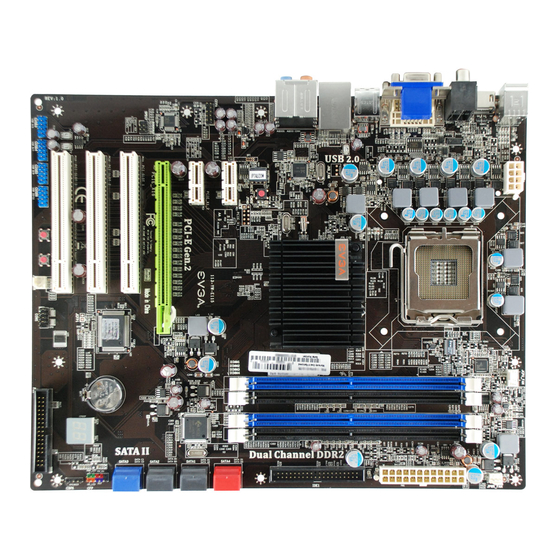
Page 16: Evga Nforce 730I Motherboard
EVGA nForce 730i Motherboard The EVGA nForce 730i motherboard with the NVIDIA GeForce 9300/nForce 730i single chip is a PCI Express, NVIDIA GeForce Boost Technology ready motherboard. Figure 1 shows the motherboard and Figures 2 shows the back panel connectors. - Page 17 6. 24-pin ATX Power Connector 16. Power Button 7. IDE Connector 17. RESET Button 8. Serial-ATA (SATA) Connectors 18. USB Headers 9. Front Panel Connector 19. PCI Slots 10. Speaker Connector 20. PCI Express x16 Slot Figure 1. EVGA nForce 730i Motherboard Layout EVGA...
-
Page 18: Chassis Back Panel Connectors
Blue Line-In Line-In Line-In Green Line-Out Front Speaker Out Front Speaker Out Pink Mic In Mic In Mic In Orange Center/Subwoofer Center/Subwoofer Black Rear Speaker Out Rear Speaker Out Grey Side Speaker Out Figure 2. Chassis Back Panel Connectors EVGA... -
Page 19: Hardware Installation
Safety Instructions To reduce the risk of fire, electric shock, and injury, always follow basic safety precautions. Remember to remove power from your computer by disconnecting the AC main source before removing or installing any equipment from/to the computer chassis. EVGA... -
Page 20: Preparing The Motherboard
CPU, you have a safe place to store it. notches on the CPU Align the notches in the processor with the notches on the socket. Lower the processor straight down into the socket with out tilting or sliding it into the socket. EVGA... -
Page 21: Installing The Cpu Fan
Install into either slots 1 and 3 or 2 and 4. The four DIMM sockets are divided into two colors to help you identify the channel pairs. To obtain best performance, simply mount DIMM sockets of the same color. Four DIMMs: Install into slots 1, 2, 3, and 4. EVGA... -
Page 22: Installing The Motherboard
Note: Be sure that the CPU fan assembly has enough clearance for the chassis covers to lock into place and for the expansion cards. Also make sure the CPU Fan assembly is aligned with the vents on the covers. EVGA... -
Page 23: Installing The I/O Shield
Ensure that the fan assembly is aligned with the chassis vents according to the fan assembly instruction. Secure the motherboard with a minimum of eight-to-ten screws. Connecting Cables and Setting Switches This section takes you through all the connections and switch settings necessary on the motherboard. This will include: EVGA... - Page 24 8-pin ATX 12V power ( PW12 Internal Headers Front panel Speaker USB Headers Audio Serial ATA II Chassis Fans Expansion slots CMOS Clear Button See Figure 1 on page 6 to locate the connectors and Button referenced in the following procedure. EVGA...
-
Page 25: 24-Pin Atx Power (Pw1)
PW1 connector Plug power cable from system power supply to PW1 Card edge Figure 2. PW1 Motherboard Connector Table 1. PW1 Pin Assignments Connector Signal Signal +3.3V +3.3V +3.3V -12V PS_ON PWROK RSVD +5V_AUX +12V +12V +3.3V EVGA... -
Page 26: 8-Pin Atx 12V Power (Pw12)
If an ATA-66/100 disk drive and a disk drive using any other IDE transfer protocol are attached to the same cable, the maximum transfer rate between the drives may be reduced to that of the slowest drive. IDE Connector IDE Connector Card-edge side EVGA... -
Page 27: Connecting Serial Ata Cables
SATA D0 (bottom) end to the motherboard SATA 1 connector. SATA A1 (top) SATA A0 (bottom) Connect the end without the lock to the drive. Note: The SATA3 port only supports AHCI and RAID mode. It does not support IDE mode. EVGA... -
Page 28: Connecting Internal Headers
PWR BTN PWRSW Ground RESET Attach the Reset switch cable from No Connect the front panel of the case to these Empty Empty two pins. The system restarts when switch is pressed. RESET EVGA... -
Page 29: Usb Headers
Connect the two ends of the cables to the USB 2.0 headers on the motherboard. Table 3. USB 2.0 Header Pins Connector Signal Card Edge 5V_DUAL Data- USB 2.0 Header Data+ Empty Signal 5V_DUAL Data- Data+ No Connect EVGA... -
Page 30: Audio
PORT1_R PRECENCE_J PORT2_R SENSE1_RETURN SENSE_SEND Empty PORT2_L SENSE2_RETURN SPK Header The speaker header is connects to the case’s speaker for PC beeps. Table 5. CSPK Header Pins Connector Signal Speaker Header Empty 1 2 3 4 Speaker Header Speaker EVGA... -
Page 31: Fan Connections
CPU Fan Ground +12V Sense Control Power Fan +12V Sense Ground Note: The CPU fan cable can be either a 3-pin or a 4-pin connector. Connect a 3-pin connector to pins 1, 2, and 3 on the motherboard connector. EVGA... -
Page 32: Com1
PCI slots. For a full list of PCI Express x16 graphics card supported by this motherboard, go to www.nvidia.com/estore 1 – PCI slot 3 2 – PCI slot 2 – PCI slot 1 4 – PCI-E x16 slot 5 – PCI-E x1 slot 6 – PCI-E x1 slot EVGA... -
Page 33: Pci Slots
If the card is not seated properly, it could cause a short across the pins. Secure the card’s metal bracket to the chassis back panel with the screw used to hold the blank cover. EVGA... -
Page 34: Onboard Buttons
BIOS. The CMOS can be cleared by press the RESET CMOS button. Clear CMOS Button RESET and POWER Button These onboard buttons allow you to easily turn the system ON or OFF. It is especially convenient for debugging or testing the system. RESET POWER Button Button EVGA... -
Page 35: Post Port Debug Led And Led Status Indicators
DIMM LED (LED1): This LED to show the power status of Memory. CHIPSET LED (LED2): This LED to show the power status of Chipset. CPU LED (LED3): This LED to show the power status of CPU. CHIPSET LED DIMM LED EVGA... -
Page 36: Configuring The Bios
Setup menus. Detailed descriptions of the BIOS parameters are also provided. This section includes the following information: Enter BIOS Setup Main Menu Standard CMOS Features Advanced BIOS Features Advanced Chipset Features Integrated Peripherals Power Management Setup PnP/PCI Configurations PC Health Status Frequency/Voltage Control EVGA... -
Page 37: Enter Bios Setup
To go back to the previous menu, press Note that on the BIOS screens all data in white is for information only, data in yellow is changeable, data in blue is non-changeable, and data in a red box is highlighted for selection. EVGA... - Page 38 Use this menu to set up onboard peripherals such as IDE, RAID, USB, LAN, and MAC control. Power Management Setup Use this menu to configure power management, power on, and sleep features. PnP/PCI Configurations Use this menu to modify the system’s Plug-and-Play and PCI configurations. EVGA...
- Page 39 Use this command to set, change, and disable the password used to access the BIOS menu. Save & Exit Setup Use this command to save settings to CMOS and exit setup. Exit Without Saving Use this command to abandon all setting changes and exit setup. EVGA...
-
Page 40: Standard Cmos Features Menu
F6:Fail-Safe Defaults F7:Optimized Defaults Figure 4. Standard CMOS Features Menu Note that all data in white is for information only, data in yellow is changeable, data in blue is non-changeable, and data in a red box is highlighted for selection. EVGA... -
Page 41: Date And Time
SATA Channel sub-menu SATA 1 (A0) [Manual} Access Mode [CHS] IDE Auto-Detect [Press Enter] Capacity 0 MB SATA 1 (A0) [None} Access Mode Auto Cylinder Head Capacity 0 MB Precomp Landing Zone Cylinder Sector Head Precomp Landing Zone Sector EVGA... - Page 42 Key in a DEC number : For HDD less than 528 MB. For HDD greater than 528 MB and :Move ENTER:Accept ESC:Abort supporting LBA (Logical Block Addressing). Large For HDD greater than 528 MB but not supporting LBA. Auto Recommended mode. EVGA...
-
Page 43: Drive A
..[ ] error, the system stops and prompts you. No Errors ..[ ] All , But Keyboard ..[ ] All , But Diskette ..[ ] All , But Disk/Key ..[ ] EVGA :Move ENTER:Accept ESC:Abort... -
Page 44: Evga
1048576K BIOS POST determines the amount of base (or conventional) memory installed in the system. Extended Memory BIOS determines how much extended memory is present during the POST. Total Memory This value represents the total memory of the system. EVGA... -
Page 45: Advanced Bios Features Menu
Boot Up NumLock Status [On] Security Option [Setup] APIC Mode [Enabled] MPS Version Control For OS [1.4] Full Screen LOGO Show [Disabled] :Move Enter:Select +/-/PU/PD:Value F10:Save ESC:Exit F1:General Help F5:Previous Values F6:Fail-Safe Defaults F7:Optimized Defaults Figure 5. Advanced BIOS Features Menu EVGA... -
Page 46: Removable Device Priority
1. Ch0 M. : BENQ DVD DC DW1810 First/Second/Third Boot Device Use this option to set the priority sequence of the devices booted at power on. Use the keys to scroll through the options or press Page Up Page Down EVGA... -
Page 47: Boot Other Device
The Security Options allows you to require a password every time the system boots or only when you enter setup. Select to require a password to gain Setup access to the CMOS Setup screen. Select to require a password to System access the CMOS Setup screen and when the system boots. EVGA... -
Page 48: Apic Mode
Page Down scroll through the options. Full Screen LOGO Show This option allows you to enable or disable the display of the full-screen logo when the system boots. Use the keys to toggle Page Up Page Down between Enable Disable EVGA... -
Page 49: Advanced Chipset Features Menu
Onboard GPU [Always Enable] Frame Buffer Size [256M] HPET Support [Enabled] Retrain PCIE dev to Gen2 [Enabled] System BIOS Cacheable [Enabled] :Move Enter:Select +/-/PU/PD:Value F10:Save ESC:Exit F1:General Help F5:Previous Values F6:Fail-Safe Defaults F7:Optimized Defaults Figure 6. Advanced Chipset Features EVGA... -
Page 50: Spread Spectrum Control
PCI Slot and PCIEx. If you use Hybird SLI card, the PCI Slot option not appear. Hybrid SLI This item allows you set the Hybrid SLI function if you install a Hybrid SLI card. The options are Auto and Disabled. EVGA... -
Page 51: Display Detection
When HPET is Disabled, the APIC timer is used. Retrain PCIE dev to Gen2 By default all capable devices populated in PCIE slots will be retrained to Gen2 speed. This can be disabled (to force Gen1 only). The options are Disabled and Enabled. EVGA... -
Page 52: System Bios Cacheable
System BIOS Cacheable This function allows you to enable or disable caching the system BIOS. EVGA... -
Page 53: Integrated Peripherals Menu
Storage Config [Press Enter] Item Help Onbard Devices [Press Enter] Legacy Devices [Press Enter] Main Level USB Device Setting [Press Enter] :Move Enter:Select +/-/PU/PD:Value F10:Save ESC:Exit F1:General Help F5:Previous Values F6:Fail-Safe Defaults F7:Optimized Defaults Figure 7. Integrated Peripherals Menu EVGA... -
Page 54: Storage Config
RAID: Create a RAID 0, 1, 0+1, 5 and JBOD configuration. AHCI: Use the AHCI (Advanced Host Controller Interface) to enables advanced SATA features for improved performance with NCQ and Hot-plug features Linux AHCI: Use the function for Linux AHCI. EVGA... -
Page 55: Onboard Devices
When this function is enabled the Post Port LED will display the CPU’s current temperature. Options are Enabled and Disabled. Legacy Devices Press to display the Legacy Devices menu. Enter Onboard FDC Controller [Enabled] Onboard Serial Port 1 [3F8/IRQ4] EVGA... -
Page 56: Usb Device Setting
Use this function to enable or disable support for USB keyboard under DOS. USB Mouse Function Use this function to enable or disable support for USB Mouse under DOS. USB Storage Function Use this function to enable or disable legacy support of USB Mass Storage. EVGA... -
Page 57: Power Management Setup Menu
Hot Key Power On [Ctrl-F1] PWRON After PWR-Fail [Off] :Move Enter:Select +/-/PU/PD:Value F10:Save ESC:Exit F1:General Help F5:Previous Values F6:Fail-Safe Defaults F7:Optimized Defaults Figure 8. Power Management Setup Menu ACPI Function This function allows you to enable or disable the ACPI function. EVGA... -
Page 58: Acpi Suspend Type
Page Up Page Down numbers or enter the number using the keyboard number or the keys. – POWER ON Function This function allows you to define the power-on function by the key press activity. Options for this function are: EVGA... -
Page 59: Hot Key Power On
This function enables your computer to automatically restart or return to its last operating status after power returns from a power failure. Off: The system stays off after a power failure. On: The system stays on after a power failure EVGA... -
Page 60: Pnp/Pci Configuration Menu
Item Help IRQ Resources Press Enter Main Level PCI/VGA Palette Snoop [Disabled] ** PCI Express relative items ** Maximum Payload Size [4096] :Move Enter:Select +/-/PU/PD:Value F10:Save ESC:Exit F1:General Help F5:Previous Values F6:Fail-Safe Defaults F7:Optimized Defaults Figure 9. PnP/PCI Configuration Menu EVGA... -
Page 61: Resources Controlled By
Use PCI/ISA PnP for devices compliant with the plug-and-play standard, whether designed for PCI or ISA Bus architecture. PCI/VGA Palette Snoop This function on the PnP/PCI Configuration menu allows you to enable or disable the Palette Snoop function. EVGA... -
Page 62: Maximum Payload Size
TLP payload size (in bytes) for the PCI Express devices. Use the keys to scroll through sizes or enter the number using Page Up Page Down the keyboard numbers or use the keys to go up and down the list of – sizes. EVGA... -
Page 63: Pc Health Status Menu
+/-/PU/PD:Value F10:Save ESC:Exit F1:General Help F5: Previous Values F7:Defaults Figure 2. PC Health Status Menu All of the values shown in are dynamic and change as the speed and Blue voltages of the various components change with system usage. EVGA... -
Page 64: Smartfan Function
By Temperature calculates the fan speed according to different temperature range. How effective Smart CPU Fan is will depend on fan design. Most fans have built-in thermistor and may self adjust its speed. Some fans have very limited duty cycle range open to fan control. EVGA... -
Page 65: Frequency/Voltage Control Menu
FSB & Memory Config [Press Enter] System Voltage [Press Enter] Main Level CPU Feature [Press Enter] CPU Clock Ratio Unlock [Disabled] :Move Enter:Select +/-/PU/PD:Value F10:Save ESC:Exit F1:General Help F5:Previous Values F6:Fail-Safe Defaults F7:Optimized Defaults Figure 3. Frequency/Voltage Control Menu EVGA... -
Page 66: System Clocks
Frequency Settings Current CPU Freq, MHz This value is set by the CPU Multiplier (value cannot be changed by the user). FSB Clock. MHz This value is set by the system (value cannot be changed by the user). To EVGA... -
Page 67: Fsb & Memory Config
F1:General Help F5:Previous Values F6:Fail-Safe Defaults F7:Optimized Defaults Figure 5. FSB & Memory Config Menu FSB - Memory Clock Mode Use the keys to scroll through the FSB and Page Up Page Down Memory Clock Mode options. The options are: EVGA... - Page 68 MEM (DDR), MHz Use the keys to scroll through new values for the memory frequency – or type in a new value. Note that the reflects the actual Actual MEM (DDR) frequency that takes effect when the system reboots. EVGA...
-
Page 69: Memory Timing Setting
:Move Enter:Select +/-/PU/PD:Value F10:Save ESC:Exit F1:General Help F5:Previous Values F6:Fail-Safe Defaults F7:Optimized Defaults Optimal Use the keys to select Optimal Page Up Page Down Optimal. prohibits you from manually setting any timing. All timing is set for optimal performance. EVGA... - Page 70 : The Write recovery time (options are Auto and 2 through 6). : This is the minimum write-to-read delay with the same chip tWTR selected (options are Auto and 1 through 15). : This is the DRAM refresh rate (options are , and tREF Auto 7.8uS 3.9uS EVGA...
-
Page 71: System Voltages
F1:General Help F5:Previous Values F6:Fail-Safe Defaults F7:Optimized Defaults Figure 6. System Voltages Menu CPU Core Use the keys to scroll through the voltages or select Page Up Page Down to automatically set the voltage level for the CPU Core. [Auto] EVGA... - Page 72 [Auto] set the voltage. GTLVREF Lane 3 This function defines the voltage level for GTLVREF Lane 3. Use the Page keys to select a voltage or select to automatically Page Down [Auto] set the voltage. EVGA...
-
Page 73: Cpu Feature
There are two mode options that can be selected. The Native mode is for fully support ACPI OS (ex. WINXP, VISTA...), SMM mode is for legacy OS (ex. WIN2K…). Limit CPUID MaxVal Use this function to enable the set limit of the CPUID MaxVal to 3. Set to Disable for Win XP. EVGA... -
Page 74: Cpu Clock Ratio Unlock
CPU Clock Ratio Unlock Select Enabled, if you install a CPU that supports this feature. The following item become available to select a multiplier to set the CPU frequency. If your CPU multiplier is locked this option will be unavailable. EVGA... -
Page 75: Installing Drivers And Software
Windows XP 32bit and 64bit and is Vista-capable. The kit comes with a CD that contains utility drivers and additional NVIDIA software. The CD that has been shipped with your EVGA motherboard contains the following software and drivers: NVIDIA nForce motherboard drivers... - Page 76 IGP - Integrated Graphics Processors IRQ - Interrupt Request JBOD - Just a Bunch of Disks JEDEC - Joint Electron Device Engineering Council LAN - Local Area Network LCD - Liquid Crystal Display LGA – Land Grid Array LN2 – Liquid Nitrogen Cooling EVGA...
- Page 77 SLI - Scalable Link Interface SPD - Serial Presence Detect SPDIF - Sony/Philips Digital Interconnect Format SPP - System Platform Processors TCP/IP - Transmission Control Protocol/Internet Protocol USB - Universal Serial Bus VDroop - V-core Voltage Drop VGA - Video Graphics Array EVGA...
- Page 78 POST Codes for the EVGA nForce 730i Motherboard This section provides the Award POST Codes (Table 6) for the EVGA nForce 730i Motherboard during system boot up. The POST Codes are displayed on the LED POST Codereadout located directly onboard the motherboard.
- Page 79 HPM init Init Heuristic Power Management (HPM) Reserved Program chipset Early Programming of chipset registers Init PNP Init PNP Shadow VBIOS Shadow system/video BIOS Clock Gen Init onboard clock generator and sensor Setup BDA Setup BIOS DATA AREA (BDA) Reserved EVGA...
- Page 80 Verify 8259 Channel 2 masked interrupts by alternately turning off and on the interrupt lines. Reserved Reserved Test Stuck Interrupt Turn off interrupts then verify no 8259's interrupt mask register is on. Test 8259 Force an interrupt and verify the interrupt occurred. Reserved EVGA...
- Page 81 PnP Init Display PnP logo and PnP early init Reserved Setup Virus Setup virus protect according to Protect Setup Reserved Awdflash Load If required, will auto load Awdflash.exe in POST Reserved Onboard I/O Init Initializing onboard superIO Reserved Reserved EVGA...
- Page 82 Reserved Detect serial ports Initialize serial ports. Reserved Reserved Detect parallel ports Initialize parallel ports. Reserved HDD Write Protect HDD check for write protection Reserved Reserved POST error check Check POST error and display them and ask for user EVGA...
- Page 83 Set low stack Boot via INT 19h. Base CPU test Read/Write CPU registers Memory Presence Base memory detect Early Memory Board Initialization Extend Memory Turn on extended memory, cache initialization Special Display First display initialization Early Shadow Early shadow enable for fast boot EVGA...
- Page 84 If interrupt occurs in protected mode. Unclaimed NMI If unmasked NMI occurs, display Press F1 to disable NMI, F2 reboot. Program MCP To program chipset from defaults values Setup Pages E1- Page 1, E2 - Page 2, etc. Boot EVGA...