Ricoh Aficio SP C400DN Hardware Manual
Hardware guide
Hide thumbs
Also See for Aficio SP C400DN:
- User manual (608 pages) ,
- Software manual (370 pages) ,
- Manual (12 pages)
Table of Contents
Advertisement
Read this manual carefully before you use this machine and keep it handy for future reference. For safe and correct use, be sure to read "Safety
Information" before using the machine.
Guide to the Printer
1
Installing Options
2
Connecting the Printer
3
Configuration
4
Paper and Other Media
5
Replacing Consumables and Maintenance Kit
6
Cleaning the Printer
7
Adjusting the Printer
8
Troubleshooting
9
Removing Misfed Paper
10
Appendix
11
Operating Instructions
Hardware Guide
Advertisement
Table of Contents
Troubleshooting

Related Manuals for Ricoh Aficio SP C400DN


Summary of Contents for Ricoh Aficio SP C400DN
-
Page 1: Operating Instructions
Operating Instructions Hardware Guide Guide to the Printer Installing Options Connecting the Printer Configuration Paper and Other Media Replacing Consumables and Maintenance Kit Cleaning the Printer Adjusting the Printer Troubleshooting Removing Misfed Paper Appendix Read this manual carefully before you use this machine and keep it handy for future reference. For safe and correct use, be sure to read “Safety Information”... -
Page 3: Table Of Contents
TABLE OF CONTENTS Trademarks......................1 Positions of RWARNING and RCAUTION labels ..........2 Manuals for This Printer..................4 How to Read This Manual ..................5 Symbols ........................5 Description for the Specified Model..............6 Installing the Operating Instructions ..............7 1. Guide to the Printer Exterior: Front View....................9 Exterior: Rear View ....................11 Inside........................12 Control Panel......................13... - Page 4 4. Configuration Ethernet Configuration..................65 Using DHCP - Detecting the Network Address Automatically........68 Making Network Settings for Using Netware............70 IEEE 802.11b (Wireless LAN) Configuration .............72 5. Paper and Other Media Paper and Other Media Supported by This Printer...........77 Paper Recommendations..................81 Loading Paper......................81 Storing Paper ......................81 Types of Paper and Other Media ................
- Page 5 9. Troubleshooting Error & Status Messages on the Control Panel ..........157 Panel Tone......................159 Printer Does Not Print ..................160 Checking the port connection.................161 Other Printing Problems ...................163 Additional Troubleshooting ................168 10.Removing Misfed Paper Removing Misfed Paper ..................171 When the Paper Misfeed Message Appears (Cover A)........172 When the Paper Misfeed Message Appears (Cover Z) ........175 11.Appendix Moving and Transporting the Printer...............177...
-
Page 7: Trademarks
Trademarks Microsoft, Windows and Windows NT are registered trademarks of Microsoft Corporation in the United States and/or other countries. ® ® ® ® Adobe , PostScript , Acrobat , PageMaker and Adobe Type Manager are reg- istered trademarks of Adobe Systems Incorporated. ®... -
Page 8: Positions Of Rwarning And Rcaution Labels
Positions of RWARNING and RCAUTION labels This machine has labels for RWARNING and RCAUTION at the positions shown below. For safety, please follow the instructions and handle the machine as indicated. BEU001S High temperature parts. Turn off the main power and be careful when replacing fusing unit/removing misfed paper. - Page 9 Do not incinerate spilled toner or used toner. Toner dust is flammable and might ignite when exposed to an open flame. Disposal should take place at an authorized dealer or an appropriate collection site. If you dispose of the used toner containers yourself, dispose of them according to local regulations.
-
Page 10: Manuals For This Printer
Manuals for This Printer For particular functions, see the relevant parts of the manual. ❖ Safety Information Provides information on safe usage of this machine. To avoid injury and prevent damage to the machine, be sure to read this. ❖ Quick Installation Guide Contains procedures for removing the printer from its box, connecting it to a computer, and installing its driver. -
Page 11: How To Read This Manual
How to Read This Manual Symbols This manual uses the following symbols: Indicates important safety notes. Ignoring these notes could result in serious injury or death. Be sure to read these notes. They can be found in the Safety Information. Indicates important safety notes. -
Page 12: Description For The Specified Model
Description for the Specified Model In this manual, the following items explain about the printer for the specified models: This explains about the 220-240 V model printer. You can identify the model by checking the label on the rear of the printer. Read if you purchase this model. -
Page 13: Installing The Operating Instructions
Installing the Operating Instructions The CD-ROM “Manuals” provided with the printer contains an HTML Operat- ing Instructions Manual in HTML version. Follow this instructions to install it. Important ❒ System Requirements : • Windows 95/98/Me, Windows 2000/XP, Windows Server 2003 or Win- dows NT4.0. -
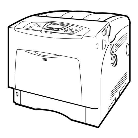
Page 15: Guide To The Printer
1. Guide to the Printer Exterior: Front View AQC021S Control Panel Tray 1 Contains keys for printer control and a Up to 550 sheets of plain paper can be display that shows the printer status. loaded. Front Cover Standard Tray Open the front cover to replace the fusing Output is stacked here with the print side unit or transfer roller, or to remove... - Page 16 Guide to the Printer Note ❒ When setting paper larger than A5 K, pull out the paper extender as shown. For details about the sizes and types of paper that can be used, see p.77 “Paper and Other Media Supported by This Printer”. AQC022S...
-
Page 17: Exterior: Rear View
Exterior: Rear View Exterior: Rear View AQC200S Controller Board Expansion Card Slots Slide this out to install options such as the Install expansion cards in these slots. memory unit, user account enhance unit There are three slots. or printer hard disk. Plug cables such as When you use the expansion card, use the USB cable and Ethernet cable into the center slot. -
Page 18: Inside
Guide to the Printer Inside BEU002S Toner Cartridge Inner Cover Loads from the printer rear, in the order Open this when replacing the photo con- of yellow (Y), cyan (C), magenta (M), and ductor units or intermediate transfer black (K). unit. -
Page 19: Control Panel
Control Panel Control Panel AQC024S Display Power indicator Displays current printer status and error This indicator remains lit while the power is messages. on. It is unlit when the power is off or while the printer is in the Energy Saver mode. For details about error messages, see p.157 “Error &... -
Page 20: Display Panel
Guide to the Printer Display Panel This section describes configuration using the display panel on the initial screen. AQC060S Operational status or messages [Prt.Jobs] Displays current machine status, such as Press to display print jobs sent from a “Ready”, “Offline”, and “Printing...”. computer. -
Page 21: Installing Options
2. Installing Options Available Options This section describes how to install options. By installing options, you can improve the printer performance and have an ex- panded variety of features to use. For the specifications of each option, see p.182 “Specifications”. R CAUTION: •... -
Page 22: Option Installation Flow Chart
Installing Options Option Installation Flow Chart Installing multiple options in the following order is recommended: Attach the paper feed unit (Paper Feed Unit Type 4000). Attach the paper feed units to the bottom of the printer. You can attach up to two paper feed units. Up to 1750 sheets of paper can be loaded in total. -
Page 23: Installing Options
Available Options Installing Options Install options in the positions shown in the illustration. ❖ Exterior AET061S Paper Feed Unit Type 4000 Loads up to 550 sheets of paper. Up to two paper feed units, can be installed on the printer. Installed tray units are identified as “Tray 2”... -
Page 24: Sdram Module
Installing Options ❖ Interior AQC040S Memory Unit Type D 128MB/ Optional units Memory Unit Type E 256MB See p.49 “Attaching Data Overwrite (SDRAM module) Security Unit Type E”. Install 128 MB or 256 MB SDRAM See p.51 “Attaching the Camera Direct module into the controller board slot. -
Page 25: Caution When Re-Installing The Controller Board
Available Options Caution when re-installing the controller board This section describes handling the controller board when installing options. If you slide out the controller board to install the SDRAM module, the user ac- count enhance unit, or the printer hard disk, carefully follow the instruction be- low to re-install the controller board. -
Page 26: Attaching Paper Feed Unit Type 4000
Installing Options Attaching Paper Feed Unit Type 4000 When installing multiple options, install the paper feed unit first. R CAUTION: • The printer weights approximately 50 kg (110.3 lb.). When moving the print- er, use the inset grips on both sides, and lift slowly. The printer will break or cause injury if dropped. - Page 27 Attaching Paper Feed Unit Type 4000 Lift the printer using the inset grips on both sides of the printer. AET034S Important ❒ The printer should always be lifted by at least two people. Align the printer with the two upright pins on the paper feed unit and then lower the printer slowly.
- Page 28 Installing Options Note ❒ When moving the printer, remove the paper feed unit. ❒ After finishing installation, you can check whether the paper feed unit is properly installed: Print the configuration page from the [List/Test Print] menu. If it is installed properly, “Tray 2” or “Tray 2”, “Tray 3” will appear for “Connection Equipment”...
-
Page 29: Attaching Memory Unit Type D 128Mb, Memory Unit Type E 256Mb (Sdram Module)
Attaching Memory Unit Type D 128MB, Memory Unit Type E 256MB (SDRAM Module) Attaching Memory Unit Type D 128MB, Memory Unit Type E 256MB (SDRAM Module) R CAUTION: • Do not touch the inside of the controller board compartment. Doing so may cause a malfunction or a burn. - Page 30 Installing Options Using both hands, slide the controller board completely out. AQC650S Place the controller board on a flat surface, and then loosen the four screws to remove the cover. AQC660S The screws cannot be fully removed. Be sure to install the SDRAM module as shown. AQC670S Two slots are provided for the SDRAM modules.
- Page 31 Attaching Memory Unit Type D 128MB, Memory Unit Type E 256MB (SDRAM Module) When installing an SDRAM module in a vacant slot, align the notch of the SDRAM module with the slot, and then insert the module vertically. AET076S Press down the SDRAM module, until it clicks into place. AET077S When replacing the default SDRAM module, press down the levers on both sides ( ) to remove the default module ( ).
- Page 32 Installing Options To install other options on the controller board, follow the appropriate in- stallation procedure(s), and then screw down the controller board cover. Fasten the four screws to attach the cover. AQC700S Align the controller board with the left and right rails, and then push it carefully in, until it stops.
- Page 33 Attaching Memory Unit Type D 128MB, Memory Unit Type E 256MB (SDRAM Module) Note ❒ Be sure to return the provided screwdriver to its original position on the inside of the front cover. ❒ After finishing the installation, you can check the memory unit is properly installed: Print the configuration page from the [List/Test Print] menu.
-
Page 34: Attaching User Account Enhance Unit Type E
Installing Options Attaching User Account Enhance Unit Type E R CAUTION: • Do not touch the inside of the controller board compartment. Doing so may cause a malfunction or a burn. Important ❒ Before touching the User Account Enhance Unit, ground yourself by touch- ing something metal to discharge any static electricity. - Page 35 Attaching User Account Enhance Unit Type E Grasp the handles, and then pull the controller board carefully out. AQC640S Using both hands, slide the controller board completely out. AQC650S Place the controller board on a flat surface. Loosen the five screws to re- move the cover AQC660S The screws cannot be fully removed.
- Page 36 Installing Options Be sure to install the User Account Enhance Unit as shown. AQC680S Align the notch of User Account Enhance Unit, and then insert it into the controller board, pressing it down until it clicks into place. AET081S Make sure that User Account Enhance Unit is firmly connected to the con- troller board.
- Page 37 Attaching User Account Enhance Unit Type E Fasten the four screws to attach the cover. AQC700S Align the controller board with the left and right rails, and then push it carefully in, until it stops. AQC710S Push on the area of the controller board that is marked “PUSH”. Push in the controller board until it can go no further.
- Page 38 Installing Options Note ❒ After finishing installation, you can check User Account Enhance Unit is properly installed: Print the configuration page from the [List/Test Print] menu. If it is installed properly, “Accounting Module” will appear for “De- vice Connection” on the configuration page. ❒...
-
Page 39: Attaching Hard Disk Drive Type 4000
Attaching Hard Disk Drive Type 4000 Attaching Hard Disk Drive Type 4000 R CAUTION: • Do not touch the inside of the controller board compartment. Doing so may cause a machine malfunction or a burn. Important ❒ Before touching the hard disk drive, touch something metal to discharge any static electricity. - Page 40 Installing Options ❖ Power Cable AET085S ❖ Four Screws AET086S Turn off the power, and then unplug the power cable. Loosen the three screws securing the controller board. AQC630S The screws cannot be fully removed.
- Page 41 Attaching Hard Disk Drive Type 4000 Grasp the handles, and then pull the controller board carefully out. AQC640S Using both hands, slide the controller board completely out. AQC650S Place the controller board on a flat surface, and then loosen the four screws to remove the cover.
- Page 42 Installing Options Be sure to install the hard disk drive unit as shown. AET069S Use the screws supplied with the hard disk drive to secure the unit to the controller board. AET087S Connect the power cable to the hard disk drive and controller board. AET088S...
- Page 43 Attaching Hard Disk Drive Type 4000 Connect the flat cable to the hard disk drive and the controller board. Con- nect the blue end of the flat cable to the controller board. AQC0006S When installing other options on the controller board, do not close the con- troller board, but go to the steps for installing the option.
- Page 44 Installing Options Fasten the controller board to the printer using the three screws. AQC720S When the power is turned on, the hard disk drive will be formatted automat- ically. Note ❒ After finishing installation, you can check whether the hard disk drive is properly installed: Print the configuration page from the [List/Test Print] menu.
-
Page 45: Attaching Ieee 802.11B Interface Unit
Attaching IEEE 802.11b Interface Unit Attaching IEEE 802.11b Interface Unit R CAUTION: • Do not touch the inside of the controller board compartment. Doing so may cause a machine malfunction or a burn. Important ❒ Before touching the 802.11b interface unit, touch something metal to discharge any static electricity. - Page 46 Installing Options • Antenna Cap AAL888S Turn off the power, and then unplug the power cable. Loosen the two screws and remove the cover of the 802.11b interface unit installation unit. AQC091S The removed cover is not used when installing the interface unit. Fully insert the 802.11b interface unit.
- Page 47 Attaching IEEE 802.11b Interface Unit Attach the antenna to the card with the label facing down and the uneven side of the antenna facing up. AET096S With the antenna and the indented end toward you, slowly insert the inter- face card until it stops. AQC097S Hold the antenna cap with the cut off corners towards you and fit it over the card.
-
Page 48: Attaching Ieee 1284 Interface Board Type A
Installing Options Attaching IEEE 1284 Interface Board Type A R CAUTION: • Do not touch inside the controller board compartment. Doing so may cause a machine malfunction or a burn. Important ❒ Before handling the 1284 interface board, touch something metal to discharge static electricity. - Page 49 Attaching IEEE 1284 Interface Board Type A Fully insert the 1284 interface board. AET102S Confirm that the 1284 interface board is firmly connected to the controller board. Tighten the two screws to secure the 1284 interface board. AQC103S Note ❒ Use the supplied adaptor to make the connection with the computer. ❒...
-
Page 50: Attaching The Usb Host Interface Board Type A
Installing Options Attaching the USB Host Interface Board Type A Important ❒ When connecting a digital camera to the printer via USB, the USB port of the USB host interface board is required. ❒ Before handling the USB host interface board, ground yourself by touching something metal to discharge any static electricity. - Page 51 Attaching the USB Host Interface Board Type A Fully insert the USB host interface board. AQC042S Tighten the two screws to secure the USB host interface board. AQC044S Check the USB host interface board is inserted firmly to the controller board. Note ❒...
-
Page 52: Attaching Gigabit Ethernet Board Type A
Installing Options Attaching Gigabit Ethernet Board Type A Important ❒ The printer's ethernet and USB ports are not available when the gigabit eth- ernet board is attached to the printer. Instead, you can use the ethernet port and USB port mounted on the board. ❒... - Page 53 Attaching Gigabit Ethernet Board Type A Turn off the power, and then unplug the power cable. Disconnect the cables from the ethernet port and the USB port of the printer, and cover each port with its protective cap. AQC046S Loosen the two screws and remove the cover of the Gigabit ethernet board installation unit.
- Page 54 Installing Options Tighten the two screws to secure the Gigabit ethernet board. AQC045S Check the Gigabit ethernet board is connected firmly to the controller board. Note ❒ After finishing installation, check the Gigabit ethernet board is installed properly: print the configuration page from the [List/Test Print] menu. If it is installed properly, you will see “Gigabit Ethernet Board”...
-
Page 55: Attaching Data Overwrite Security Unit Type E
Attaching Data Overwrite Security Unit Type E Attaching Data Overwrite Security Unit Type E Important ❒ Protect the Data Overwrite Security unit from physical shocks. ❒ Use the right slot for the Data Overwrite Security unit. Check the package contains the following: ❖... - Page 56 Installing Options Reattach the cover over the Data Overwrite Security unit. Fasten the screw to secure the cover. AQC107S Note ❒ Do not touch the Data Overwrite Security unit while the printer is in use. It may come loose, even if pushed only slightly.
-
Page 57: Attaching The Camera Direct Print Card
Attaching the Camera Direct Print Card Attaching the Camera Direct Print Card Important ❒ Protect the Camera Direct Print card from physical shocks. ❒ Use the right slot for the Camera Direct Print card. Check the package contains the following: ❖... - Page 58 Installing Options Reattach the cover over the Camera Direct Print card. Fasten the screw to se- cure the cover. AQC107S Note ❒ Do not touch the Camera Direct Print card while the printer is in use. It may come loose, even if pushed only slightly.
-
Page 59: Attaching Vm Card Type D
Attaching VM Card Type D Attaching VM Card Type D Important ❒ Protect VM Card Type D from physical shocks. ❒ Use the right slot for the VM card. Check the package contains the following: ❖ VM Card Type D AET104S Turn off the power, and then unplug the power cable. - Page 60 Installing Options Reattach the cover over the VM card. Fasten the screw to secure the cover. AQC107S Note ❒ Do not touch the VM card while the printer is in use. It may come loose, even if pushed only slightly.
-
Page 61: Attaching Data Storage Card Type A
Attaching Data Storage Card Type A Attaching Data Storage Card Type A Important ❒ Protect Data Storage Card Type A from physical shocks. ❒ Use the right slot for the Data Storage card. Check the package contains the following: ❖ Data Storage Card Type A AET104S Turn off the power, and then unplug the power cable. - Page 62 Installing Options Reattach the cover over the Data Storage card. Fasten the screw to secure the cover. AQC107S Note ❒ Do not touch the Data Storage card while the printer is in use. It may come loose, even if pushed only slightly.
-
Page 63: Connecting The Printer
3. Connecting the Printer Network Connection Follow the procedure below to connect the printer to the computer through the network. Prepare the hub and other network devices before connecting the 10BASE-T or 100BASE-TX cable to the printer's Ethernet port. Alternatively, the optional gigabit ethernet board, which supports 1000BASE-T, is available. - Page 64 Connecting the Printer If the gigabit ethernet board is attached, connect the ethernet cable to the board. AQC056S The printer's ethernet and USB ports are not available when the gigabit eth- ernet board is attached to the printer. Connect the other end of the cable to the printer's network, such as a hub. Note ❒...
-
Page 65: Reading The Led Lamps
Network Connection Reading the LED Lamps ❖ For standard ethernet port AQC070S Yellow: comes on when 100BASE-TX is being used. It comes off when 10BASE-T is being used. Green: comes on when the printer is properly connected to the network. ❖... -
Page 66: Usb Connection
Connecting the Printer USB Connection Important ❒ USB2.0 interface cable is not supplied. Obtain it separately, according to the computer you are using. ❒ USB connection is possible under Windows 98 SE/Me/2000/XP, Windows Server 2003, Mac OS 9.x, and Mac OS X. ❒... -
Page 67: Connecting A Digital Camera
Connecting a digital camera Connecting a digital camera This printer supports direct printing, which allows you to print images taken with digital cameras without using a computer. The following describes how to connect the printer to a digital camera. AQC047S Important ❒... - Page 68 Connecting the Printer Use the USB cable supplied with the USB host interface board to connect the printer and the digital camera. Connect the flat connector of the USB ca- ble to the USB host interface board. AQC063S Connect the square-shaped connector on the opposite end of the USB cable to the digital camera.
-
Page 69: Parallel Connection
Parallel Connection Parallel Connection Important ❒ The parallel interface cable is not supplied with the printer. ❒ The printer's parallel connection is a standard bidirectional interface that re- quires an IEEE 1284-compliant 36-pin parallel cable and host computer paral- lel port. ❒... - Page 70 Connecting the Printer...
-
Page 71: Configuration
4. Configuration Ethernet Configuration Make the following network settings according to the network interface you are using. You can use SmartDeviceMonitor for Admin or a Web browser to make IP ad- dress-related settings in a TCP/IP-capable environment. Important ❒ Configure the printer for the network using the control panel. ❒... - Page 72 Configuration Press the {Menu} key. AQC001S Select [Host Interface] using {T} or {U}, and then press the {OK} key. Select [Network] using {T} or {U}, and then press the {OK} key. Select [Effective Protocol] using {T} or {U}, and then press the {OK} key. Select the network protocol using {T} or {U}, and then press the {OK} key.
- Page 73 Ethernet Configuration Select [Effective] or [Invalid] using {T} or {U}, and then press the {OK} key. Set other protocols you need to set in the same way. • Select [Invalid] for unused protocols. • Enable IPv4 to use the Pure IPv4 environment of NetWare 5/5.1, NetWare 6/6.5.
-
Page 74: Using Dhcp - Detecting The Network Address Automatically
Configuration Select [Specify] using {T} or {U}, and then press the {OK} key. If you do not select [Specify] in this step, the address you set will not be saved. Press the {Menu} key to return to the initial screen. Print a configuration page to confirm the settings made. - Page 75 Ethernet Configuration Select [Host Interface] using {T} or {U}, and then press the {OK} key. Select [Network] using {T} or {U}, and then press the {OK} key. Select [Machine IPv4 Address] using {T} or {U}, and then press the {OK} key. Select [Auto-Obtain (DHCP)] using {T} or {U}, and then press the {OK} key.
-
Page 76: Making Network Settings For Using Netware
Configuration Making Network Settings for Using Netware If you use NetWare, select the frame type for NetWare. Select one of the items below if necessary. • Auto Select • Ethernet II • Ethernet 802.2 • Ethernet 802.3 • Ethernet SNAP Important ❒... - Page 77 Ethernet Configuration Select [NW Frame Type] using {T} or {U}, and then press the {OK} key. Select the frame type using {T} or {U}, and then press the {OK} key. Press the {Menu} key to return to the initial screen. Print a configuration page to confirm the settings made.
-
Page 78: Ieee 802.11B (Wireless Lan) Configuration
Configuration IEEE 802.11b (Wireless LAN) Configuration Configure the printer to use IEEE 802.11b (Wireless LAN). The following table shows the control panel settings and their default values. These items appear in the [Host Interface] menu. Setting Name Default Value Communication Mode 802.11 Ad hoc Channel •... - Page 79 IEEE 802.11b (Wireless LAN) Configuration Select [IEEE 802.11b] using {T} or {U}, and then press the {OK} key. Select [Communication Mode] using {T} or {U}, and then press the {OK} key. Select the transmission mode of IEEE 802.11b using {T} or {U}, and then press the {OK} key.
- Page 80 Configuration Enter the channel using {T} or {U}, and then press the {OK} key. Set [Communication Speed] in the same way. The factory default is [Auto Select]. If you need to change the transmitting speed depending on environment you are using, select the appropriate trans- mitting speed.
- Page 81 IEEE 802.11b (Wireless LAN) Configuration Print a configuration page to confirm the settings made. Reference SSID can also be set using a Web browser. For details, see the Web Image Monitor Help, and “Configuring the Network Interface Board Using Web Browser”, Software Guide.
- Page 82 Configuration Enter the characters using {V}, or {W}, and then press the {OK} key. You can switch among upper/lower cases, numeric codes, and symbols by pressing [ABC/123]. When using 64 bit WEP, up to 10 characters can be used for hexadecimal and up to five characters for ASCII.
-
Page 83: Paper And Other Media
5. Paper and Other Media Paper and Other Media Supported by This Printer This section describes the paper size, feed direction, and the maximum amount of paper that can be loaded into each paper tray in this printer. Note ❒ The following symbols and terminology are used to represent the feed direction. In this manual On the display Paper feed direction... - Page 84 Paper and Other Media 114 × 162 C6 Env (4.49 × 6.38 inches) DL Env (4.33 × 8.66 inches) 110 × 220 98.4 × 190.5 × 7 Monarch Env (3 inches) Custom Size 195 × 267 16K (7.68 × 10 inches) The size cannot be set automatically if you use the following model: The size cannot be set automatically if you use the following model:...
- Page 85 Paper and Other Media Supported by This Printer ❖ Input Paper Sizes (Inch version) 8.26 ” × 11.69 ” 7.17 ” × 10.12 ” 5.83 ” × 8.26 ” 5.04 ” × 7.17 ” 4.13 ” × 5.63 ” ” × 14 ” Legal (LG) ”...
- Page 86 Paper and Other Media ❖ Paper weight and number of sheets to be set Maximum number of Supported paper weight sheets (plain paper) Tray 1 52 - 216 g/m (14 - 58 lb.) 550 (80 g/m , 20 lb.) Bypass Tray 52 - 216 g/m (14 - 58 lb.) 100 (80 g/m...
-
Page 87: Paper Recommendations
Paper Recommendations Paper Recommendations Loading Paper Important ❒ Do not use ink-jet printer paper because it may stick to the fusing unit and cause a paper misfeed. ❒ When printing on OHP transparencies that have a print side, load them with the print side over on the bypass tray. -
Page 88: Types Of Paper And Other Media
Paper and Other Media Types of Paper and Other Media Plain Paper Paper thickness 60.2 - 104.7 g/m (16 - 28 lb.) • [Plain Paper 1]: 60.2 - 90.2 g/m (16 - 24 lb.) • [Plain Paper 2]: 90.2 - 104.7 g/m (24 - 28 lb.) Printer setup Make the following two settings using the control panel:... - Page 89 Paper Recommendations Glossy Paper • Press the {Menu} key, select [Paper Input] , and then select Printer setup [Glossy Paper] for the selected tray's paper type. Printer driver setup Select [Glossy] in the [Paper type:] list. Duplex Printing Possible Note ❒...
-
Page 90: Thick Paper
Paper and Other Media Thick Paper Paper thickness • [Thick Paper]: 104.7 - 216 g/m (28 - 58 lb.) • [Thick Paper 1]: 104.7 - 157 g/m (28 - 42 lb.) • [Thick Paper 2]: 157 - 216 g/m (42 - 58 lb.) Printer setup Make the following settings using the control panel: •... - Page 91 Paper Recommendations Label Paper Printer setup Make the following settings using the control panel: • Press the {Menu} key, select [Paper Input], and then select [Label Paper] for the selected tray's paper type. Printer driver setup Click [Labels] in the [Paper type:] list. Enabled paper feeding tray Any input tray can be used.
- Page 92 Paper and Other Media Envelopes Printer setup Make the following settings using the control panel: • Press the {Menu} key, select [Paper Input], and then select [Enve- lope] for the selected tray's paper type. Printer driver setup Select [Envelope] in the [Paper type:] list. Enabled paper feeding tray Any input tray can be used.
-
Page 93: Paper Not Supported By This Printer
Paper Recommendations Paper not supported by this printer Avoid using the following paper as they are not supported by this printer. • Paper meant for an ink-jet printer • Bent, folded, or creased paper • Curled or twisted paper • Torn paper •... -
Page 94: Print Area
Paper and Other Media Print Area The following shows the print area for this printer. Be sure to set the print mar- gins correctly by the application. ❖ Paper Print area Feed direction Approx. 4.2 mm (0.17 inches) Approx. 4.2 mm (0.17 inches) Note ❒... -
Page 95: Loading Paper
Loading Paper Loading Paper This describes how to load paper into the paper tray and bypass tray. R CAUTION: • Do not pull out the paper tray forcefully. If you do, the tray might fall and cause an injury. Loading Paper in Tray 1 and the optional paper feed unit The following example explains loading procedure for the standard paper tray (Tray 1). - Page 96 Paper and Other Media Slide the green switch on the front of the tray to the type of paper to be loaded. When loading paper of 75 g/m , 20 lb., or thicker, slide the switch to the left. AET043S Load the new paper stack print side up, making sure the paper is flush against the paper guides.
- Page 97 Loading Paper Setting a Paper Size by Using the Control Panel To load paper whose size cannot be selected automatically, set the paper size on the control panel. Follow the procedure described below to set the paper size. Press the {Menu} key. AQC001S Select [Paper Input] using {T} or {U}, and then press the {OK} key.
- Page 98 Paper and Other Media Select the paper size you want to set using the scroll keys, and then press the {OK} key. • • Press the {Menu} key to return to the initial screen.
- Page 99 Loading Paper Setting the Paper Size Automatically Important ❒ If you specify the paper size using the control panel, and want to return the settings to load paper size automatically, load paper into the paper tray, and follow this procedure. Press the {Menu} key.
- Page 100 Paper and Other Media Select [Auto Detect] using the scroll keys, and then press the {OK} key. • • Press the {Menu} key to return to the initial screen. Note ❒ Some paper sizes are not selected automatically. Check the followings, de- pending on the printer model: •...
- Page 101 Loading Paper Specifying Custom Size Paper for Tray 1 and the Optional Paper Feed Unit Important ❒ When printing on custom size paper, specify the paper size using the control panel or printer driver. ❒ The custom size paper selected using the printer driver overrides that select- ed using the control panel.
- Page 102 Paper and Other Media Select [Paper Size: (tray name)] using {T} or {U}, and then press the {OK} key. For example, [Paper Size: Tray 1] is selected for Tray 1 as shown. Select [Custom Size] using the scroll keys, and then press the {OK} key. •...
- Page 103 Loading Paper Specifying a Paper Type for Tray 1 and the Optional Paper Feed Unit Improve printer performance by selecting the optimum paper type for the tray. You can select from the following paper types: • Plain Paper, Recycled Paper, Special Paper 1, Special Paper 2, Special Paper 3, Color Paper, Letterhead, Preprinted Paper, Label Paper, Bond Paper, Card- stock, OHP (Transparency), Envelope, Thick Paper 1, Thick Paper 2 (157 - 209.4 g/m...
- Page 104 Paper and Other Media Press the {Menu} key to return to the initial screen. Note ❒ If the printing result is wet or smudged with the [Plain Paper] setting, Make the following settings using the control panel: • Select [Plain Paper] for the paper type according to the procedure above. •...
-
Page 105: Loading Paper In The Bypass Tray
Loading Paper Loading Paper in the Bypass Tray Important ❒ Shuffle the paper before loading the stack onto the tray, so multiple sheets are not fed in together. ❒ Set the size and direction of the loaded paper on the control panel or with the printer driver. - Page 106 Paper and Other Media Slide the side guides outward, and then load paper print side down, until it stops. AQC005S Adjust the side guides to fit the paper width. AQC006S...
- Page 107 Loading Paper Specifying Standard Size Paper for the Bypass Tray This describes how to load standard size paper into the bypass tray. Set the paper size using the control panel. Press the {Menu} key. AQC001S Select [Paper Input] using {T} or {U}, and then press the {OK} key. Select [Paper Size: Bypass] using {T} or {U}, and then press the {OK} key.
- Page 108 Paper and Other Media Press the {Menu} key to return to the initial screen. Note ❒ To load thick paper, OHP transparencies, or envelopes, make settings for thick paper, envelope, or OHP transparencies using the control panel and printer driver. ❒...
- Page 109 Loading Paper Select [Paper Size: Bypass] using {T} or {U}, and then press the {OK} key. Select [Custom Size] using the scroll keys, and then press the {OK} key. • • Enter the vertical value using {T} or {U}, and then press the {OK} key. By pressing the key, the value increases or decreases by 0.1 mm.
- Page 110 Paper and Other Media Specifying a Paper Type for the Bypass Tray By selecting the paper type you want to load, the printer performs better. You can select from the following paper types: • Plain Paper, Recycled Paper, Special Paper 1, Special Paper 2, Special Paper 3, Color Paper, Letterhead, Preprinted Paper, Label Paper, Bond Paper, Card- stock, OHP (Transparency), Envelope, Thick Paper 1, Thick Paper 2, Thin Pa- per, Plain: Dup.Back (reverse side of plain paper), Thick 1: Dup.Back, Thick...
- Page 111 Loading Paper Select the paper type using {T} or {U}, and then press the {OK} key. Press the {Menu} key to return to the initial screen. Note ❒ If the printing result is wet or smudged with the [Plain Paper] setting, Make the following settings using the control panel: •...
-
Page 112: Switching Between Paper Trays
Paper and Other Media Switching between Paper Trays When paper of the same size is loaded in both the standard tray and the paper feed unit (option), and when [Auto Tray Select] is set with the printer driver, paper will be fed from the standard tray when you start printing. To print on paper loaded in the paper feed unit, switch the tray to be used to the paper feed unit using [Tray Priority] in the [Paper Input] Menu. -
Page 113: Replacing Consumables And Maintenance Kit
6. Replacing Consumables and Maintenance Kit Replacing the Toner Cartridge R WARNING: • Do not incinerate spilled toner or used toner. Toner dust is flammable and might ignite when exposed to an open flame. • Do not store toner, used toner, or toner containers in a place with an open flame. - Page 114 Replacing Consumables and Maintenance Kit ❖ When to replace the toner cartridge If any of the toner cartridge indicators on the initial screen appear to show it is empty, replace the indicated toner cartridge. Replace the toner cartridge if the following message appears on the display: “Add Toner: (color)”...
- Page 115 Replacing the Toner Cartridge Remove the toner cartridge you want to replace. Turn the locking lever of the toner cartridge towards the triangle mark ( ), and then lift out the toner cartridge ( ). BEU006S • Do not shake the removed toner cartridge. Remaining toner may leak. •...
- Page 116 Replacing Consumables and Maintenance Kit Install the toner cartridge. Holding the toner cartridge horizontally ( ) with the locking lever on the upper side, install the toner cartridge bottom first, and then move the locking lever to the triangle mark ( ). BEU008S Turn the locking lever to the circle mark.
-
Page 117: Replacing The Photo Conductor Unit
Replacing the Photo Conductor Unit Replacing the Photo Conductor Unit The following procedure describes replacing the first photo conductor unit from the right. The procedure is the same for all four photo conductor units. ❖ When to replace the photo conductor unit Replace the photo conductor unit if the following messages appear: •... - Page 118 Replacing Consumables and Maintenance Kit Turn off the power, and then unplug the power cable. Carefully open the left cover. AQC012S Turn the two green levers counterclockwise ( ), and then slowly open the inner cover ( ). AQC013S The photo conductor units are installed as shown. From the right, the units are attached in the order of black (K), magenta (M), cyan (C), and yellow (Y).
- Page 119 Replacing the Photo Conductor Unit Remove the photo conductor unit you want to replace. Turn the green lever counterclockwise to unlock the unit. (The black photo conductor unit is used in this example.) AET138S Pull out the ring pull handle of the photo conductor unit. AET139S Hook your finger through the ring pull handle, and then slowly pull out the photo conductor unit.
- Page 120 Replacing Consumables and Maintenance Kit Remove the new photo conductor unit from its box. For black, install one; for color, install all three. AET141S Remove the protecting cover. Do not remove the tape yet. AET142S Check the installation position of the photo conductor unit. Install the unit where the colored labels correspond.
- Page 121 Replacing the Photo Conductor Unit Install the photo conductor unit with the tape still attached. Align the tip of the photo conductor unit with the opening, and then slowly insert the unit, until it stops. AET143S Take care that nothing comes into contact with the surface of the photo con- ductor unit.
- Page 122 Replacing Consumables and Maintenance Kit Turn the green lever clockwise to lock the unit. AET146S Close the inner cover. Lock the inner cover by pressing in ( ) and then turning the two green levers clockwise ( ). AQC014S Carefully close the left cover. Plug in the power cable, and then turn on the power.
-
Page 123: Replacing The Intermediate Transfer Unit
Replacing the Intermediate Transfer Unit Replacing the Intermediate Transfer Unit R CAUTION: • The inside of this printer becomes very hot. Do not touch parts labelled “v” (indicating a hot surface). Touching these parts will result in burns. ❖ When to replace the transfer unit •... - Page 124 Replacing Consumables and Maintenance Kit Carefully open the printer's front cover (A) by pulling the left and right side levers. AQC015S Turn the green lever of the transfer unit counterclockwise to unlock the unit. AET138S Pull out the handle of the transfer unit. Grasp the handle and the green le- ver firmly, and then slowly pull out the transfer unit, until the green line marked on the upper surface of the unit appears.
- Page 125 Replacing the Intermediate Transfer Unit When the green line appears, pull up the handles on the upper surface and support the transfer unit with your other hand. AET950S Grasp the raised up handles with both hands, and then pull the transfer unit completely out.
- Page 126 Replacing Consumables and Maintenance Kit Hold both upper handles, and then slide the transfer unit along the guide rails into the printer. AET953S The upper handles must be raised to insert the unit. When the upper handles touch the printer body, lower the handles, and then push in the transfer unit, until it stops.
- Page 127 Replacing the Intermediate Transfer Unit Close the inner cover. Lock the inner cover by pressing in ( ) and then turning the two green levers clockwise ( ). AQC014S Carefully close the left cover. Plug in the power cable, and then turn on the power. The printer starts calibration.
-
Page 128: Replacing The Waste Toner Bottle
Replacing Consumables and Maintenance Kit Replacing the Waste Toner Bottle R WARNING: • Do not incinerate spilt or used toner. Toner dust is flammable and ig- nites when exposed to naked flame. • Dispose at an authorized dealer or approved collection site. If you dis- pose of the used toner containers yourself, do so according to local regulations. - Page 129 Replacing the Waste Toner Bottle Use the supplied seals to avoid toner spills before removing the filled waste toner bottle. Attach the seals to the five sponge pads, allowing them to act as covers. AET153S Slide the green lever to the unlock position. AET154S Lift the waste toner bottle with the seal still attached, and then remove the waste toner bottle from the left cover.
- Page 130 Replacing Consumables and Maintenance Kit Insert the projection part into the pivot inside the left cover, and then place the waste toner bottle in the horizontal position. AET156S The green lever will slide automatically when the waste toner bottle is set. AET157S Check the waste toner bottle is correctly locked.
-
Page 131: Replacing The Maintenance Kit
Replacing the Maintenance Kit Replacing the Maintenance Kit R WARNING: • Do not risk electric shock by handling the power cord or plug with wet hands. R CAUTION: • The inside of this printer becomes very hot. Do not touch parts labelled “v” (indicating a hot surface). -
Page 132: Replacing The Friction Pad
Replacing Consumables and Maintenance Kit Replacing the Friction Pad Replace all the friction pads in the tray. The following procedure shows how to replace the tray's friction pad (Tray 1). Carefully slide the paper tray (Tray 1) out, until it stops. Then, lift the front slightly, and then pull the tray completely out. - Page 133 Replacing the Maintenance Kit Turn the paper tray right way up, and remove the friction pad from the tray. The friction pad spring may come loose. Be careful not to lose the friction pad spring. AET200S Insert the new friction pad in the paper tray. Place the spring over the central prong of the new friction pad and align the friction pad with the grooves of the paper tray.
-
Page 134: Replacing The Paper Feed Roller
Replacing Consumables and Maintenance Kit Replacing the Paper Feed Roller Replace all feed rollers including the printer and the optional Paper Feed Unit(s). The following procedure shows how to replace the printer's paper feed rollers. R CAUTION: • The printer weights approximately 50 kg (110.3 lb.). When moving the print- er, use the inset grips on both sides, and lift slowly. - Page 135 Replacing the Maintenance Kit While sliding the green lock lever to the right ( ), set the new roller ( ). Then, return the green lock lever to its original position ( ). AET401S Check the green lock lever secures the roller correctly by making sure the new roller rotates smoothly.
-
Page 136: Replacing The Transfer Roller
Replacing Consumables and Maintenance Kit Replacing the Transfer Roller Carefully open the printer's front cover (A) of by pulling left and right side levers. AQC018S Pinch the green clips on both ends of the transfer roller. AET163S Do not touch the roller area of the transfer roller. It may stain your hands or clothes. - Page 137 Replacing the Maintenance Kit Insert the new transfer roller by placing its underside edge into the grooves shown in the illustration. AET165S Secure the transfer roller using the green fastening clips mentioned in step AET166S The transfer roller appears insecurely set, but this is intentional. Close the front cover (A).
-
Page 138: Replacing The Fusing Unit
Replacing Consumables and Maintenance Kit Replacing the Fusing Unit R CAUTION: • The fusing unit becomes very hot. When installing a new fusing unit, turn off the printer and wait at least an hour. before replacing the old fusing unit. Not allowing the unit to cool may result in burns. - Page 139 Replacing the Maintenance Kit Prepare a new fusing unit. AET183S Align the new fusing unit with the left and right rails. AQC184S Push the fusing unit carefully in, until it stops. Then, pull up the fixing lever. AQC181S Close the front cover (A).
-
Page 140: Replacing The Dustproof Filter
Replacing Consumables and Maintenance Kit Replacing the Dustproof Filter The dustproof filter is attached to the left side of the printer, as shown. AQC019S Turn off the power, and then unplug the power cable. Use the grips on both sides to turn and then remove the dustproof filter cover. - Page 141 Replacing the Maintenance Kit Attach the new dustproof filters to the covers at a time. The dustproof fil- ters are all the same size. AET160S Reattach the dustproof filter covers to the printer one at a time. AET161S AET162S Plug in the power cable, and then turn on the power.
- Page 142 Replacing Consumables and Maintenance Kit...
-
Page 143: Cleaning The Printer
7. Cleaning the Printer Cautions to Take When Cleaning R WARNING: • Do not remove any covers or screws other than those specified in this manual. Some parts of the machine are at a high voltage and could give you an electric shock. Also, if the machine has laser systems, di- rect (or indirect) reflected eye contact with the laser beam may cause serious eye damage. -
Page 144: Cleaning The Friction Pad
Cleaning the Printer Cleaning the Friction Pad If the friction pad is dirty, a multi-feed or a misfeed might occur. In this case, clean the pad as follows: Slowly slide the paper tray (Tray 1) out, until it stops. After that, lift the front of the tray slightly, and then pull the tray completely out. - Page 145 Cleaning the Friction Pad Lift the front of the tray, and slide it carefully into the printer until it stops. AET045S Do not slide the paper tray in with force. If you do, the front and side guides might move. Note ❒...
-
Page 146: Cleaning The Paper Feed Roller
Cleaning the Printer Cleaning the Paper Feed Roller If the paper feed roller is dirty, a misfeed might occur. In this case, clean the roll- er as follows: R CAUTION: • When lifting the printer, use the grips on both sides of the printer, otherwise the printer might fall and cause personal injury. - Page 147 Cleaning the Paper Feed Roller Slide the green lock lever to the right ( ), so that the paper feed roller can be released ( ). AET402S Wipe the rubber part of the roller with a soft damp cloth. After that, wipe it with a dry cloth to remove the water.
- Page 148 Cleaning the Printer Insert the plug of the power cord into the wall socket securely. Connect all the interface cables that were removed. Turn on the power switch. Note ❒ Follow the same procedure to clean the paper feed roller of the optional Pa- per Feed Unit.
-
Page 149: Cleaning The Registration Roller
Cleaning the Registration Roller Cleaning the Registration Roller R CAUTION: • The inside of this printer becomes very hot. Do not touch parts labelled “v” (indicating a hot surface). Touching these parts will result in burns. Clean the registration roller if dots (caused by specks of paper stuck to the roller) appear on printed OHP transparencies. - Page 150 Cleaning the Printer Clean the registration roller by applying a soft damp cloth while turning it. AQC172S • Do not use chemical cleaners or organic solvents such as thinners or ben- zene. • Do not touch the belt of the transfer unit and transfer roller. Carefully close the front cover (A).
-
Page 151: Adjusting The Printer
8. Adjusting the Printer Adjusting the Color Registration After moving the printer, printing on thick paper, or printing repeatedly for some time, color degradation may occur. By performing color registration ad- justment, you can restore optimum print quality. If documents show color degradation after the printer is moved, perform auto- matic color adjustment. - Page 152 Adjusting the Printer On the cofirmation screen, press[OK]. Automatic color adjustment begins. Automatic color adjustment takes about 50 seconds. A confirmation message appears when complete. Press [Exit]. Press the {Menu} key to return to the initial screen.
-
Page 153: Correcting The Color Gradation
Correcting the Color Gradation Correcting the Color Gradation Color gradation during color printing changes slightly, depending on a number of factors. If you print the same file repeatedly or toner was recently replaced, changes may occur in color tones. When this happens, to obtain suitable print re- sults, color gradation can be corrected, although it is not usually necessary to make any particular settings. -
Page 154: Set The Gradation Correction Value
Adjusting the Printer Set the Gradation Correction Value During printing, you can correct the gradation in two areas: bright part (high- light) and the medium (middle). The correction value for the highlight and the medium parts are set using [Print Sheet 1] and [Print Sheet 2] respectively. Press the {Menu} key. - Page 155 Correcting the Color Gradation If you want to perform only auto color adjusting, select [Adjust Auto Density] using {T} or {U}, and then press the {OK} key. The confirmation message appears. press [OK]. When it is completed, the confirmation message appears. press [Exit]. In the Caribration menu, select [Print Sheet 1] or [Print Sheet 2] using {T} or {U}, and then press the {OK} key.
- Page 156 Adjusting the Printer Press [Result] to check the result by printing the calibration sheet. On the confirmation screen, press [Print]. After printing, press [Yes] to save the settings. After completing all settings, press the {Menu} key to return to the initial screen.
-
Page 157: Viewing The Color Calibration Sample Sheet And Gradation Correction Sheet
Correcting the Color Gradation Viewing the Color Calibration Sample Sheet and Gradation Correction Sheet The color gradation correction value setting sheet contains two color sample col- umns “Sample 1” column for setting the highlight part, and “Sample 2” column for setting the medium part. Similarly, the gradation correction sheet contains: “Gradation correction sheet 1”... - Page 158 Adjusting the Printer ❖ Relationship between gradation correction sheet and display The printed gradation correction sheet and display correspond as shown in the following diagram: Comparing at the gradation correction sheet and correction value of each col- or, K (black), M (magenta), and C (cyan)/Y (yellow), determine the gradation correction and make settings using the control panel.
-
Page 159: Resetting The Gradation Correction Value To The Initial Value
Correcting the Color Gradation Resetting the gradation correction value to the initial value Reset the correction value default. Press the {Menu} key. AQC001S Select [Maintenance] using {T} or {U}, and then press the {OK} key. Select [Quality Maintenance] using {T} or {U}, and then press the {OK} key. Select [Color Calibration] using {T} or {U}, and then press the {OK} key. -
Page 160: Adjusting Tray Registration
Adjusting the Printer Adjusting Tray Registration You can adjust the registration of each tray. The vertical adjustment is used for all trays. Normally, you need not update the registration. But when the optional paper feed unit or the duplex unit is installed, updating is useful in some cases. Press the {Menu} key. - Page 161 Adjusting Tray Registration Select the tray you want to adjust using {T} or {U}, and then press the {OK} key. Print the test sheet to preview the settings. Confirm the position of the image on the test sheet, and then adjust the reg- istration value.
- Page 162 Adjusting the Printer Set the registration value (mm) using {T} or {U}, and then press the {OK} key. Increase the value to shift the print area in the positive direction, and decrease to shift in the negative direction. AAL708S : Print Area : Feed Direction Pressing the {U} or {T} key makes the value increase or decrease by 1.0 mm steps.
-
Page 163: Troubleshooting
9. Troubleshooting Error & Status Messages on the Control Panel This section explains what the messages that appear on the control panel mean and what to do when a particular message appears. ❖ Status Messages (in alphabetical order) Message Status Calibrating... - Page 164 Troubleshooting ❖ Alert Messages (in alphabetical order) Messages Descriptions and recommended actions Address book data error. This message appears when the previously in- stalled hard disk drive is removed and rein- stalled. To prevent this message appearing, do not remove the hard disk drive. Contact your local sales/service representative if this mes- sage appears.
-
Page 165: Panel Tone
Panel Tone Panel Tone The following table explains the meaning of the various beep patterns that the printer alerts to users about its conditions. Beep pattern Meaning Cause Two long beeps. Printer has warmed up. After cooling or being switched on, the printer has fully warmed up and is ready for use. -
Page 166: Printer Does Not Print
Troubleshooting Printer Does Not Print Possible Cause Solutions Is the power on? Confirm that the cable is securely plugged into the power outlet and the printer. Turn on the power. Does the Online indicator If not, press the{Online} key to light it. stay on? Does the Alert indicator If so, check the error message on the display and take the required... -
Page 167: Checking The Port Connection
Printer Does Not Print Checking the port connection When the printer is directly connected via the PC cable and the data-in indicator does not flash or light up, the method of checking the port connection is as fol- lows. • For a parallel port connection, port LPT 1 or LPT 2 should be set. •... - Page 168 Troubleshooting Windows XP Home Edition Access the [Control Panel] window from [Start] on the taskbar. Click [Printers and Other Hardware]. Click [Printers and Faxes]. Click to select the icon of the printer. Next, on the [File] menu, click [Proper- ties]. Click the [Port] tab.
-
Page 169: Other Printing Problems
Other Printing Problems Other Printing Problems Status Possible Causes, Descriptions, and Solutions Toner smears appear on the The paper setting may not be correct. For example, although you print side of the page. are using thick paper, the setting for thick paper may not be set. •... - Page 170 Troubleshooting Status Possible Causes, Descriptions, and Solutions Paper gets wrinkles. • Paper is damp. Use paper that has been stored properly. See p.77 “Paper and Other Media”. • Paper is too thin. See p.77 “Paper and Other Media”. • There may be a gap between the front guide and the pa- per, or between the side guides and the paper in the pa- per tray.
- Page 171 Other Printing Problems Status Possible Causes, Descriptions, and Solutions Images are cut off, or excess If you are using paper smaller than the paper size selected in pages are printed. the application, use the same size paper as that selected in the application.
- Page 172 Troubleshooting Status Possible Causes, Descriptions, and Solutions The whole printout is blurred. • Paper is damp. Use paper that has been stored properly. See p.77 “Paper and Other Media”. • If you select [Toner saving] on the [Print Quality] tab in the printer properties dialog box, printing is generally less dense.
- Page 173 Other Printing Problems Status Possible Causes, Descriptions, and Solutions When printing on plain paper, The registration roller is dirty. Clean the registration roller. white dots are obvious. See p.143 “Cleaning the Registration Roller”. PDF Direct Print is not executed • You must install an optional hard disk drive or set the (PDF file is not printed).
-
Page 174: Additional Troubleshooting
Troubleshooting Additional Troubleshooting Problems Solutions Strange noise is heard. If a supply was recently replaced or an option attached in the area the strange noise is coming from, check the supply or option is properly attached. If the strange noise persists, con- tact your sales or service representative. - Page 175 Additional Troubleshooting Problems Solutions Alert-notification level was If an Alert-notification e-mail, set with the earlier notification changed, and e-mail stopped ar- level, arrives, later e-mail will not be sent, even if the notifi- riving. cation level is changed after. When no date information is in- Make the setting for obtaining time information from the cluded in sent e-mail, the mail SNTP server.
- Page 176 Troubleshooting...
-
Page 177: Removing Misfed Paper
10. Removing Misfed Paper Removing Misfed Paper An error message appears if a paper misfeed occurs. The error message gives the location of the misfeed. Important ❒ Misfed paper may be covered in toner. Be careful not to get toner on your hands or clothes. -
Page 178: When The Paper Misfeed Message Appears (Cover A)
Removing Misfed Paper When the Paper Misfeed Message Appears (Cover A) • If the “Press A to open cover and remove paper.” message appears: A paper misfeed occurs in the paper feeding. Open the front cover (A) to re- move the misfed paper. R CAUTION: •... - Page 179 When the Paper Misfeed Message Appears (Cover A) Remove misfed paper slowly. AQC171S AQC174S If you cannot find the misfed paper, look inside the printer. If a misfeed occurs in the output area of the fusing unit, open the output cover by pulling back the levers marked “A1”...
- Page 180 Removing Misfed Paper Remove misfed paper slowly. AQC177S Close the output cover of the fusing unit. Carefully close the front cover (A). If the error message remains displayed even you have removed the misfed paper, check the input tray for a paper misfeed. Pull out the paper tray, and then carefully remove any misfed paper.
-
Page 181: When The Paper Misfeed Message Appears (Cover Z)
When the Paper Misfeed Message Appears (Cover Z) When the Paper Misfeed Message Appears (Cover Z) • If the “Press Z to open cover and remove paper.” message appears: A paper misfeed occurs in the duplex unit. Open the front cover (Z) to remove the misfed paper. - Page 182 Removing Misfed Paper...
-
Page 183: 11. Appendix
11. Appendix Moving and Transporting the Printer R CAUTION: • When moving the machine, each person should hold the handles that are located on opposite sides, and then lift it slowly. Lifting it carelessly or drop- ping it may cause an injury. •... -
Page 184: Moving The Printer
Appendix Moving the Printer R CAUTION: • When lifting the machine, use the inset grips on both sides. Otherwise the printer could break or cause an injury if dropped. • Before moving the machine, unplug the power cord from the wall outlet. If the cord is unplugged abruptly, it could become damaged. -
Page 185: Consumables
Consumables Consumables R CAUTION: • Our products are engineered to meet the highest standards of quality and functionality. When purchasing expendable supplies, we recommend using only those specified by an authorized dealer. Toner Cartridge Toner cartridge Average printable number of pages per bottle Black 6,000 pages Cyan... -
Page 186: Waste Toner Bottle
Appendix Waste Toner Bottle Name Average printable number of pages Waste Toner Bottle Type 145 50,000 pages A4/letter 5% test chart, 2 pages/ job, printing in monochrome/color only. Note ❒ The actual number of printable pages varies depending on the image volume and density, number of pages to be printed at a time, paper type and paper size used, and environmental conditions such as temperature and humidity. -
Page 187: Intermediate Transfer Unit (Transfer Unit)
Consumables Intermediate Transfer Unit (Transfer Unit) Name Average printable number of pages Intermediate Transfer Unit Type 145 100,000 pages A4/letter 5% test chart, 2 pages/job, printing in monochrome/color only. Note ❒ The actual number of printable pages varies depending on the image volume and density, number of pages to be printed at a time, paper type and paper size used, and environmental conditions such as temperature and humidity. -
Page 188: Specifications
Appendix Specifications Mainframe ❖ Configuration: Desktop ❖ Print Process: Laser beam scanning & Electrophotographic printing 4 drums tandem method ❖ First Print Speed: × 11K) Monochrome: 10 sec or less (A4K/8 × 11K) Color: 15 sec or less (A4K/8 Note ❒... - Page 189 Specifications ❖ Paper Input Capacity: Standard Paper Tray 550 sheets Bypass Tray 100 sheets 550 sheets × 1, 550 sheets × 2 Optional Paper Feed Units Paper weight: 80 g/m (20 lb. bond) ❖ Power Source: • 220 - 240 V, 6A or more, 50/60 Hz •...
- Page 190 Appendix ❖ Noise Emission Sound Power Level Mainframe only Stand-by 39 dB (A) During Printing Monochrome: 63 dB (A) Color: 64 dB (A) Sound Pressure level Mainframe only Stand-by 26 dB (A) During Printing 51 dB (A) The preceding measurements made in accordance with ISO7779 are actual values. Measured at the position of a bystander.
-
Page 191: Options
Specifications Options Paper Feed Unit Type 4000 ❖ Paper size: × 11 inches) K, Legal (8 × 14 inch- A4K, B5K, A5K, B6K, Letter (8 × 8 × 10 × 13 es)K, 5 inchesK, Executive (7 inches)K, Folio (8 × 13 inches)K, F/GL (8 × 13 inches)K, Com#10 Env inches)K, Foolscap (8 ×... - Page 192 Appendix Memory Unit Type D 128MB/Memory Unit Type E 256MB ❖ Module Type: SO-DIMM (Small Outline Dual-in-line Memory Module) ❖ Memory Type: SDRAM (Synchronous Dynamic RAM) ❖ Number of Pins: 200 pins IEEE 802.11b Interface Unit Type H ❖ Transmission Spec.: Based on IEEE 802.11b (Wireless LAN) ❖...
- Page 193 Specifications IEEE 802.11b Interface Unit Type I ❖ Transmission Spec.: Based on IEEE 802.11b (Wireless LAN) ❖ Protocol: IPv4, IPv6, IPX/SPX, AppleTalk Note ❒ SmartDeviceMonitor and Web Image Monitor are supported. ❖ Data Transfer Speed: Auto select from below speed 1 Mbps, 2 Mbps, 5.5 Mbps, 11 Mbps ❖...
- Page 194 Appendix Gigabit Ethernet Board Type A ❖ Interface Connector: • Ethernet (10Base-T, 100Base-TX, 1000Base-T) • USB 2.0 It requires a USB computer port and cable that support USB 2.0. ❖ Data Transmission Speed: • Ethernet: 1000 Mbps, 100 Mbps, 10 Mbps •...
-
Page 195: Index
INDEX Data Overwrite Security Unit Type E 1284 Interface Board Data Storage Card Type A 802.11b Interface Unit DHCP Display panel Display panel, messages Additional Troubleshooting Dustproof Filter Adhesive labels Adjusting the Color Registration Adjusting Tray Registration Envelopes Appendix Error Attaching 1284 Interface Board Ethernet Attaching 802.11b Interface Unit... - Page 196 Maintenance Kit Set the Gradation Correction Value Memory Unit Specifications Specifying a paper type Memory Unit (SDRAM module) Bypass Tray Messages Optional Paper Feed Unit Moving and Transporting the Printer Tray 1 Specifying custom size paper Bypass Tray Network Optional Paper Feed Unit Tray 1 Specifying standard size paper Bypass Tray...
- Page 197 Copyright © 2007...
- Page 198 Model Number: SP C400DN / Aficio SP C400DN EN USA G158-8611...