Table of Contents
Advertisement
Advertisement
Table of Contents

Related Manuals for MSI 661FM Series


Summary of Contents for MSI 661FM Series
- Page 1 661FM Series MS-6540G (v2.X) Micro ATX Mainboard G52-M6540G3...
-
Page 2: Fcc-B Radio Frequency Interference Statement
Manual Rev: 2.2 Release Date: March 2004 FCC-B Radio Frequency Interference Statement This equipment has been tested and found to comply with the limits for a class B digital device, pursuant to part 15 of the FCC rules. These limits are designed to provide reasonable protection against harmful interference when the equip- ment is operated in a commercial environment. -
Page 3: Copyright Notice
Copyright Notice The material in this document is the intellectual property of MICRO-STAR INTERNATIONAL. We take every care in the preparation of this document, but no guarantee is given as to the correctness of its contents. Our products are under continual improvement and we reserve the right to make changes without notice. -
Page 4: Safety Instructions
Safety Instructions Always read the safety instructions carefully. Keep this User’s Manual for future reference. Keep this equipment away from humidity. Lay this equipment on a reliable flat surface before setting it up. The openings on the enclosure are for air convection hence protects the equipment from overheating. -
Page 5: Table Of Contents
Safety Instructions .................. iv Chapter 1. Getting Started ..............1-1 Mainboard Specifications ..............1-2 Mainboard Layout ................1-4 MSI Special Features ................ 1-5 Live BIOS™ /Live Driver™ ............1-6 Live Monitor™ ................1-7 Color Management ..............1-8 Chapter 2. Hardware Setup ..............2-1 Quick Components Guide .............. - Page 6 Serial Port Connector: COMA ..........2-12 VGA Connector ................ 2-12 IEEE 1394 Port (Optional) ............2-12 RJ-45 LAN Jack (Optional) ............2-13 Audio Port Connectors ............2-13 Parallel Port Connector: LPT1 ........... 2-14 Connectors ..................2-15 Floppy Disk Drive Connector: FDD1.......... 2-15 Fan Power Connectors: CPUFAN1/SYSFAN1 ......
- Page 7 Advanced BIOS Features ..............3-8 Advanced Chipset Features ............3-12 Integrated Peripherals ..............3-15 Power Management Setup .............. 3-19 PNP/PCI Configurations ..............3-23 PC Health ..................3-25 Frequency/Voltage Control ............. 3-27 Load Fail-Safe/Optimized Defaults ........... 3-28 Set Supervisor/User Password ............3-29 Appendix: Using 4- or 6-Channel Audio Function ........
-
Page 8: Chapter 1. Getting Started
Hardware Setup Getting Started Thank you for purchasing 661FM Series (MS-6540G v2.X) Micro ATX mainboard. The 661FM series is based on ® ® 661FX & SiS 963/963L chipsets and provides 6 USB 2.0 ports for high-speed data transmission. With all these special designs, the 661FM series delivers a high perfor- mance and professional desktop platform solution. -
Page 9: Mainboard Specifications
MS-6540G Micro ATX Mainboard Mainboard Specifications † Socket 478 for P4 Celeron/Northwood CPU with FSB400/533/800MHz up to 2.8GHz. † Socket 478 for P4 Prescott CPU with FSB533/800MHz . (For the latest information about CPU, please visit http://www.msi.com.tw/program/ products/mainboard/mbd/pro_mbd_cpu_support.php ) Chipset † SiS ®... - Page 10 Hardware Setup † One CNR slot. On-Board IDE † Dual IDE controllers integrated in SiS ® 963/963L. † Support Bus Master, Ultra DMA 66/100/133 operation modes. † Can connect up to four IDE devices. On-Board Peripherals † On-Board Peripherals include: - 1 floppy port supports 2 FDDs with 360K, 720K, 1.2M, 1.44M and 2.88 Mbytes.
-
Page 11: Mainboard Layout
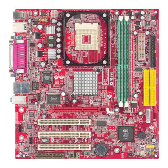
Line-In Winbond Line-Out W83627HF J1394_1 AGP Slot (Optional) Realtek 8801B PCI Slot 1 Realtek 8201BL PCI Slot 2 JCD1 963/963L JSP1 PCI Slot 3 JUSB1 Codec BATT SYSFAN1 JCI1 JAUD1 JBAT1 JFP1 661FM Series (MS-6540G) v2.X Micro ATX Mainboard... -
Page 12: Msi Special Features
Hardware Setup MSI Special Features PC Alert™ 4 The PC Alert 4 is a utility you can find in the CD-ROM disk. The utility is just like your PC doctor that can detect the following PC hardware status during real time operation: ö... -
Page 13: Live Bios™ /Live Driver
BIOS/drivers online so that you don’t need to search for the correct BIOS/driver version throughout the Web site. To use the function, you need to install the “MSI Live Update 2” application. After the installation, the “MSI Live Update 2”... -
Page 14: Live Monitor
Live Monitor™ The Live Monitor™ is a tool used to schedule the search for the latest BIOS/drivers version on the MSI Web site. To use the function, you need to install the “MSI Live Update 2” application. After the installation, the “MSI Live Monitor” icon (as shown on the right) will appear on the screen. -
Page 15: Color Management
MS-6540G Micro ATX Mainboard Color Management MSI has a unified color management rule for some connectors on the mainboards, which helps you to install the memory modules, expansion cards and other peripheral devices more easily and conveniently. † Memory DDR DIMMs: light green †... -
Page 16: Chapter 2. Hardware Setup
Hardware Setup Chapter 2. Hardware Setup Hardware Setup This chapter tells you how to install the CPU, memory modules, and expansion cards, as well as how to setup the jumpers on the mainboard. It also provides the instructions on connecting the peripheral devices, such as the mouse, keyboard, etc. -
Page 17: Quick Components Guide
MS-6540G Micro ATX Mainboard Quick Components Guide CPUFAN1, p.2-15 JPW1, p.2-9 CPU, p.2-3 DDR DIMMs, p.2-7 CONN1, p.2-9 Back Panel FDD1, p.2-15 I/O, p.2-10 BIOS J1394_1, p.2-17 AGP Slot, p.2-22 IDE1, IDE2, p.2-16 JCD1, p.2-19 JSP1, p.2-20 PCI Slots, p.2-22 JUSB1, p.2-20 BATT JFP1, p.2-18... -
Page 18: Central Processing Unit: Cpu
If you do not find the heat sink and cooling fan, contact your dealer to pur- chase and install them before turning on the computer. (For the latest information about CPU, please visit http://www.msi.com.tw/program/products/mainboard/mbd/ pro_mbd_cpu_support.php ) CPU Core Speed Derivation Procedure... -
Page 19: Cpu Installation Procedures For Socket 478
MS-6540G Micro ATX Mainboard CPU Installation Procedures for Socket 478 1. Please turn off the power and unplug the power cord before Open Lever installing the CPU. 2. Pull the lever sideways away Sliding 90 degree Plate from the socket. Make sure to raise the lever up to a 90- degree angle. -
Page 20: Installing The Cpu Fan
Hardware Setup Installing the CPU Fan As processor technology pushes to faster speeds and higher performance, thermal management becomes increasingly important. To dissipate heat, you need to attach the CPU cooling fan and heatsink on top of the CPU. Follow the instructions below to install the Heatsink/Fan: 1. - Page 21 MS-6540G Micro ATX Mainboard 5. Connect the fan power cable from the mounted fan to the 3-pin fan power connec- tor on the board. fan power cable NOTES...
-
Page 22: Memory
The mainboard provides two 184-pin unbuffered DDR266/DDR333/ DDR400 DDR SDRAM, and supports the memory size up to 2GB without ECC. To operate properly, at least one DIMM module must be installed. (For the updated supporting memory modules, please visit http://www.msi.com. tw/program/products/mainboard/mbd/pro_mbd_trp_list.php ) DDR DIMM Slots... -
Page 23: Ddr Module Combination
3. The plastic clip at each side of the DIMM slot will automatically close. Volt Notch MSI Reminds You... You can barely see the golden finger if the module is properly inserted in the socket. -
Page 24: Power Supply
5V_SB CONN1 ATX 12V Power Connector: JPW1 This 12V power connector is used to provide power to the CPU. JPW1 Pin Definition SIGNAL JPW1 MSI Reminds You... Power supply of 300 (and up) watt is highly recommended for system stability. -
Page 25: Back Panel
MS-6540G Micro ATX Mainboard Back Panel The back panel provides the following connectors: L-in L-out 1394 (Optional) Parallel Mouse (Optional) Keyboard USB Ports COMA VGA Port USB Ports Mouse Connector ® The mainboard provides a standard PS/2 mouse mini DIN connector for ®... -
Page 26: Keyboard Connector
Hardware Setup Keyboard Connector ® The mainboard provides a standard PS/2 keyboard mini DIN connector ® ® for attaching a PS/2 keyboard. You can plug a PS/2 keyboard directly into this connector. Pin Definition SIGNAL DESCRIPTION Keyboard DATA Keyboard DATA No connection Ground Keyboard Clock... -
Page 27: Serial Port Connector: Coma
MS-6540G Micro ATX Mainboard Serial Port Connector: COMA The mainboard offers one 9-pin male DIN connector as serial port COM A. This port is 16550A high speed communication ports that send/receive 16 bytes FIFOs. You can attach a serial mouse or other serial device directly to it. Pin Definition 1 2 3 4 5 SIGNAL... -
Page 28: Lan Jack (Optional)
Line In Line Out 1/8” Stereo Audio Connectors MSI Reminds You... For advanced audio application, Realtek ALC 655 is provided to offer support for 6-channel audio operation and can turn rear audio connectors from 2-channel to 4-/6-channel audio. For more information on 6-channel audio operation, please refer to Appendix. -
Page 29: Parallel Port Connector: Lpt1
MS-6540G Micro ATX Mainboard Parallel Port Connector: LPT1 The mainboard provides a 25-pin female centronic connector as LPT. A parallel port is a standard printer port that supports Enhanced Parallel Port (EPP) and Extended Capabilities Parallel Port (ECP) mode. Pin Definition SIGNAL DESCRIPTION STROBE... -
Page 30: Connectors
+12V +12V CPUFAN1 SYSFAN1 MSI Reminds You... 1. Always consult the vendors for proper CPU cooling fan. 2. CPUFAN1 supports the fan control. You can install the PC Alert utility that will automatically control the CPU fan speed according to the actual CPU temperature. -
Page 31: Hard Disk Connectors: Ide1 & Ide2
IDE2 (Secondary IDE Connector) IDE2 can also connect a Master and a Slave drive. MSI Reminds You... If you install two hard disks on cable, you must configure the second drive to Slave mode by setting its jumper. Refer to the hard disk documentation supplied by hard disk vendors for jumper setting instructions. -
Page 32: Ieee 1394 Connector: J1394_1 (Optional)
Hardware Setup IEEE 1394 Connector: J1394_1 (Optional) The mainboard provides one IEEE1394 pin header that allows you to connect IEEE 1394 ports via an external IEEE1394 bracket (optional). Pin Definition SIGNAL SIGNAL TPA+ TPA- Ground Ground TPB+ TPB- J1394_1 Cable power Cable power Key (no pin) Ground... -
Page 33: Chassis Intrusion Switch Connector: Jci1
MS-6540G Micro ATX Mainboard Chassis Intrusion Switch Connector: JCI1 This connector is connected to 2-pin connector chassis switch. If the Chassis is open, the switch will be short. The system will record this status. To clear the warning, you must enter the BIOS setting and clear the status. JCI1 CINTRU Front Panel Connectors: JFP1... -
Page 34: Cd-In Connector: Jcd1
Left channel audio signal to front panel AUD_RET_L Left channel audio signal return from front panel MSI Reminds You... If you don’t want to connect to the front audio header, pins 5 & 6, 9 & 10 have to be jumpered in order to have signal output directed to the rear audio ports. -
Page 35: Front Usb Connectors: Jusb1
MS-6540G Micro ATX Mainboard Front USB Connectors: JUSB1 The mainboard provides one USB 2.0 pin header JUSB1 that is compliant ® with Intel I/O Connectivity Design Guide. USB 2.0 technology increases data transfer rate up to a maximum throughput of 480Mbps, which is 40 times faster than USB 1.1, and is ideal for connecting high-speed USB interface peripherals such as USB HDD, digital cameras, MP3 players, printers, modems and the like. -
Page 36: Jumpers
JBAT1 Keep Data Clear Data MSI Reminds You... You can clear CMOS by shorting 2-3 pin while the system is off. Then return to 1-2 pin position. Avoid clearing the CMOS while the system is on; it will damage the mainboard. -
Page 37: Slots
MS-6540G Micro ATX Mainboard Slots The motherboard provides one AGP slot, three 32-bit PCI bus slots and one CNR slot. AGP (Accelerated Graphics Port) Slot The AGP slot allows you to insert the AGP graphics card. AGP is an interface specification designed for the throughput demands of 3D graphics. It introduces a 66MHz, 32-bit channel for the graphics controller to directly ac- cess main memory. -
Page 38: Pci Interrupt Request Routing
Hardware Setup PCI Interrupt Request Routing The IRQ, abbreviation of interrupt request line and pronounced I-R-Q, are hardware lines over which devices can send interrupt signals to the microprocessor. The PCI IRQ pins are typically connected to the PCI bus INT A# ~ INT D# pins as follows: Order 1 Order 2... -
Page 39: Chapter 3. Bios Setup
BIOS Setup Chapter 3. BIOS Setup BIOS Setup This chapter provides information on the BIOS Setup program and allows you to configure the system for optimum use. You may need to run the Setup program when: ² An error message appears on the screen during the system booting up, and requests you to run SETUP. -
Page 40: Entering Setup
MS-6540G Micro ATX Mainboard Entering Setup Power on the computer and the system will start POST (Power On Self Test) process. When the message below appears on the screen, press <DEL> key to enter Setup. Press DEL to enter SETUP If the message disappears before you respond and you still wish to enter Setup, restart the system by turning it OFF and On or pressing the RESET button. -
Page 41: Getting Help
Press <Esc> to exit the Help screen. MSI Reminds You... The items under each BIOS category described in this chapter are under continuous update for better system performance. -
Page 42: The Main Menu
MS-6540G Micro ATX Mainboard The Main Menu ® Once you enter Award BIOS CMOS Setup Utility, the Main Menu (figure below) will appear on the screen. The Main Menu allows you to select from twelve setup functions and two exit choices. Use arrow keys to select among the items and press <Enter>... - Page 43 BIOS Setup Frequency/Voltage Control Use this menu to specify your settings for frequency/voltage control. Load Fail-Safe Defaults Use this menu to load the BIOS values for the best system performance, but the system stability may be affected. Load Optimized Defaults Use this menu to load factory default settings into the BIOS for stable system performance operations.
-
Page 44: Standard Cmos Features
MS-6540G Micro ATX Mainboard Standard CMOS Features The items in Standard CMOS Features Menu are divided into 11 categories. Each category includes no, one or more than one setup items. Use the arrow keys to highlight the item and then use the <PgUp> or <PgDn> keys to select the value you want in each item. - Page 45 BIOS Setup If you select Manual, related information is asked to be entered to the following items. Enter the information directly from the keyboard. This information should be provided in the documentation from your hard disk vendor or the system manufacturer. Access Mode The settings are CHS, LBA, Large, Auto.
-
Page 46: Advanced Bios Features
MS-6540G Micro ATX Mainboard Advanced BIOS Features Quick Boot Setting the item to Enabled allows the system to boot within 5 seconds since it will skip some check items Settings: Disabled, Enabled. Anti-Virus Protection The item is to set the Virus Warning feature for IDE Hard Disk boot sector protection. - Page 47 BIOS Setup MSI Reminds You... 1. Available settings for “1st/2nd/3rd Boot Device” vary depend- ing on the bootable devices you have installed. For example, if you did not install a floppy drive, the setting “Floppy” does not show up. 2. If you want to boot from any of the USB-interface devices, please set USB Keyboard/Mouse Support in SiS OnChip PCI Device of Integrated Peripherals to Enabled.
- Page 48 Setting to Enabled will increase the system performance. Settings: Enabled, Disabled. Please disable this item if your operating system doesn’t support HT Function, or unreliability and instability may occur. MSI Reminds You... Enabling the functionality of Hyper-Threading Technology for your computer system requires ALL of the following platform Components: ®...
- Page 49 BIOS Setup APIC Mode This field is used to enable or disable the APIC (Advanced Programmable Inter- rupt Controller). Due to compliance to PC2001 design guide, the system is able to run in APIC mode. Enabling APIC mode will expand available IRQs resources for the system.
-
Page 50: Advanced Chipset Features
MS-6540G Micro ATX Mainboard Advanced Chipset Features MSI Reminds You... Change these settings only if you are familiar with the chipset. DRAM Clock/Timing Control Press <Enter> and the following sub-menu appears: Current CPU/DRAM/DDR Frequency These items allow you to view the current CPU/DRAM/DDR frequency. - Page 51 BIOS Setup DRAM Timing Control This field allows you to select the DRAM timing setting. Setting to By SPD enables Max Memclock (Mhz) automatically to be determined by SPD. Selecting Manual allows users to configure these fields manually. DRAM CAS Latency When the “DRAM Timing Control”...
- Page 52 MS-6540G Micro ATX Mainboard AGP & P2P Bridge Control Press <Enter> and the following sub-menu appears: AGP Aperture Size This setting controls just how much system RAM can be allocated to AGP for video purposes. The aperture is a portion of the PCI memory address range dedicated to graphics memory address space.
-
Page 53: Integrated Peripherals
BIOS Setup Integrated Peripherals SiS OnChip IDE Device Press <Enter> and the following sub-menu appears: Internal PCI/IDE The field specifies the internal primary and secondary PCI/IDE controllers. Settings: Disabled, Primary, Secondary, Both. IDE Primary/Secondary Master/Slave PIO The four IDE PIO (Programmed Input/Output) fields let you set a PIO mode (0-4) for each of the four IDE devices that the onboard IDE interface supports. - Page 54 MS-6540G Micro ATX Mainboard driver (Windows ME, XP or a third-party IDE bus master driver). If your hard drive and your system software both support Ultra DMA/33, Ultra DMA/66, Ultra DMA/100 and Ultra DMA/133, select Auto to enable BIOS support. Settings: Auto, Disabled. IDE DMA transfer access Setting to Enabled will open DMA bus master and execute DMA action in DOS, which will make the data transferring faster.
- Page 55 BIOS Setup SiS S/W Modem This item is used to enable/disable the SiS S/W Modem. Settings: Auto, Disabled. SiS 1394 Controller This item is used to enable/disable the 1394 controller. Settings: Enabled, Disabled. SiS 10/100M Ethernet This item is used to enable/disable the 10/100M Ethernet function. Settings: Enabled, Disabled.
- Page 56 MS-6540G Micro ATX Mainboard Parallel Port Mode This item selects the operating mode for the parallel port: Normal, SPP, EPP, ECP, or ECP+EPP. SPP: Standard Parallel Port EPP: Enhanced Parallel Port ECP: Extended Capability Port ECP + EPP: Extended Capability Port + Enhanced Parallel Port Normal: Standard Parallel Port + Bi-Directional Mode.
-
Page 57: Power Management Setup
BIOS Setup Power Management Setup ACPI Function This item is to activate the ACPI (Advanced Configuration and Power Manage- ment Interface) function. If your operating system is ACPI-aware, such as Windows 98SE/2000/ME, select Enabled. Available options: Enabled, Disabled. Sleep State This item specifies the power saving modes for ACPI function. - Page 58 MS-6540G Micro ATX Mainboard Suspend Mode When you choose User Define in the Power Management item, this item is selectable. This setting allows you to select the type of Suspend mode. Setting options: Disabled (default setting), 1 min to 1 hour. MODEM Use IRQ This setting names the interrupt request (IRQ) line assigned to the modem (if any) on your system.
- Page 59 PS2MS Wakeup From S3/S4/S5 This controls how the PS/2 mouse can power on the system. Settings: Click, Move & Click, Disabled. MSI Reminds You... S3-related functions described in this section are available only when your BIOS supports S3 sleep mode.
- Page 60 MS-6540G Micro ATX Mainboard Resume By Alarm The field is used to enable or disable the function of Resume By Alarm. Settings: Disabled, Enabled. Month Alarm When Resume By Alarm is set to Enabled, the field specifies the month for Resume By Alarm.
-
Page 61: Pnp/Pci Configurations
BIOS Setup PNP/PCI Configurations This section describes configuring the PCI bus system and PnP (Plug & Play) feature. PCI, or Peripheral Component Interconnect, is a system which allows I/O devices to operate at speeds nearing the speed the CPU itself uses when communicating with its special components. - Page 62 MS-6540G Micro ATX Mainboard IRQ Resources The items are adjustable only when Resources Controlled By is set to Manual. Press <Enter> and you will enter the sub-menu of the items. IRQ Resources list IRQ 3/4/5/7/9/10/11/12/14/15 for users to set each IRQ a type depending on the type of device using the IRQ.
-
Page 63: Pc Health Status
BIOS Setup PC Health Status This section shows the status of your CPU, fan, overall system status, etc. Monitor function is available only if there is hardware monitoring mechanism onboard. Smart Fan Target Temp. ( W83627THF provides the Smart Fan system which can control the fan speed automatically depending on the current temperature to keep it with in a specific range. - Page 64 MS-6540G Micro ATX Mainboard System/CPU Temperature, CPU/System FAN Speed, Vcore, 3.3 V, +5 V, +12 V, -12 V, VBAT(V), 5VSB(V) These items display the current status of all of the monitored hardware devices/ components such as CPU voltages, temperatures and all fans’ speeds. 3-26...
-
Page 65: Frequency/Voltage Control
BIOS Setup Frequency/Voltage Control Use this menu to specify your settings for frequency/voltage control. CPU Clock Ratio End users can overclock the processor (only if the processor supports so) by specifying the CPU ratio (clock multiplier) in this field. It is available only when “Set CPU Ratio”... -
Page 66: Load Fail-Safe/Optimized Defaults
MS-6540G Micro ATX Mainboard Load Fail-Safe/Optimized Defaults The two options on the main menu allow users to restore all of the BIOS settings to the default Fail-Safe or Optimized values. The Optimized Defaults are the default values set by the mainboard manufacturer specifically for optimal performance of the mainboard. -
Page 67: Set Supervisor/User Password
Security Option is set to System, the password is required both at boot and at entry to Setup. If set to Setup, password prompt only occurs when you try to enter Setup. MSI Reminds You... About Supervisor Password & User Password: Supervisor password: Can enter and change the settings of the setup menu. -
Page 68: Appendix: Using 4- Or 6-Channel Audio Function
Using 4- or 6-Channel Audio Function Appendix: Using 4- or 6-Channel Audio Function The motherboard is equipped with Realtek ALC655 chip, which provides support for 6-channel audio output, including 2 Front, 2 Rear, 1 Center and 1 Subwoofer channel. ALC655 allows the board to attach 4 or 6 speakers for better surround sound effect. -
Page 69: Installing The Audio Driver
(Please note the screen below might be different depending on the different mainboard you purchased.) 2. Click Realtek AC97 Audio Drivers. MSI Reminds You... The AC97 Audio Configuration software utility is under con- tinuous update to enhance audio applications. Hence, the pro- gram screens shown here in this appendix may be slightly different from the latest software utility and shall be held for reference only. - Page 70 Using 4- or 6-Channel Audio Function 3. Click Next to start installing files into the system. 4. Click Finish to restart the system. Select this option...
-
Page 71: Using 4- Or 6-Channel Audio Function
MS-6540G Micro ATX Mainboard Using 4- or 6-Channel Audio Function After installing the audio driver, you are able to use the 4-/6-channel audio feature now. To enable 4- or 6-channel audio operation, first connect 4 or 6 speakers to the appropriate audio connectors, and then select 4- or 6-channel audio setting in the software utility. - Page 72 Using 4- or 6-Channel Audio Function...
- Page 73 MS-6540G Micro ATX Mainboard Connecting the Speakers When you have set the Multi-Channel Audio Function mode properly in the software utility, connect your speakers to the correct phone jacks in accordance with the setting in software utility. 2-Channel Mode for Stereo-Speaker Output Refer to the following diagram and caption for the function of each phone jack on the back panel when 2-Channel Mode is selected.
- Page 74 Using 4- or 6-Channel Audio Function 4-Channel Mode for 4-Speaker Output The audio jacks on the back panel always provide 2-channel analog audio output function, however these audio jacks can be transformed to 4- or 6- channel analog audio jacks by selecting the corresponding multi-channel operation from No.
- Page 75 Line Out function when 6-Channel Mode for 6-Speaker Output is selected. MSI Reminds You... If the Center and Subwoofer speaker exchange their audio channels when you play video or music on the computer, a converter may be required to exchange center and subwoofer audio signals.
-
Page 76: Testing The Connected Speakers
Front Left Rear Right Rear Left Subwoofer MSI Reminds You... 6 speakers appear on the “Speaker Test” window only when you select “6-Channel Mode” in the “No. of Speakers” column. If you select “4-Channel Mode”, only 4 speakers appear on the... - Page 77 MS-6540G Micro ATX Mainboard 4. While you are testing the speakers in 6-Channel Mode, if the sound coming from the center speaker and subwoofer is swapped, you should select Swap Center/Subwoofer Output to readjust these two channels. Select this function A-10...
-
Page 78: Playing Karaok
Using 4- or 6-Channel Audio Function Playing KaraOK The KaraOK function will automatically remove human voice (lyrics) and leave melody for you to sing the song. Note that this function applies only for 2-channel audio operation. Playing KaraOK 1. Click the audio icon from the window tray at the lower-right corner of the screen.