Table of Contents
Advertisement
Advertisement
Table of Contents

Related Manuals for MSI 651M-V


Summary of Contents for MSI 651M-V
- Page 1 651M-V MS-7005 (v2.X) ATX Mainboard G52-M7005X7...
-
Page 2: Fcc-B Radio Frequency Interference Statement
Manual Rev: 2.0 Release Date: February 2004 FCC-B Radio Frequency Interference Statement This equipment has been tested and found to comply with the limits for a class B digital device, pursuant to part 15 of the FCC rules. These limits are designed to provide reasonable protection against harmful interference when the equipment is operated in a commercial environment. -
Page 3: Copyright Notice
Copyright Notice The material in this document is the intellectual property of MICRO-STAR INTERNATIONAL. We take every care in the preparation of this document, but no guarantee is given as to the correctness of its contents. Our products are under continual improvement and we reserve the right to make changes without notice. -
Page 4: Safety Instructions
Alternatively, please try the following help resources for further guidance. Visit the MSI homepage & FAQ site for technical guide, BIOS updates, driver updates, and other information: http://www.msi.com.tw & http://www.msi.com. -
Page 5: Table Of Contents
FCC-B Radio Frequency Interference Statement ... ii Copyright Notice ... iii Revision History ... iii Safety Instructions ... iv Technical Support ... iv Chapter 1. Getting Started ... 1-1 Mainboard Specifications ... 1-2 Mainboard Layout ... 1-4 Chapter 2. Hardware Setup ... 2-1 Quick Components Guide ... - Page 6 Front Panel Audio Connector: JAUD1 ... 2-16 Chassis Intrusion Switch Connector: JCI1 ... 2-17 Front Panel Connectors: JFP1 & JFP2 ... 2-17 Front USB Connectors: JUSB1/JUSB2 ... 2-18 SPDIF Connector: JSP1 ... 2-18 Jumpers ... 2-19 Clear CMOS Jumper: JBAT1 ... 2-19 Slots ...
-
Page 7: Chapter 1. Getting Started
® (702 pin BGA) & SiS 962L MuTIOL Media I/O (371 BGA) chipsets and provides 6 USB 2.0 ports for high-speed data transmission. With all these special designs, the 651M-V Series delivers a high performance and professional desktop platform solution. -
Page 8: Mainboard Specifications
Mainboard Specifications Socket 478 for P4 processors (Northwood/Prescott) at 400 MHz/533 MHz Supports up to 3.06GHz. Hyper-Threading CPU. (For the latest information about CPU, please visit http://www.msi.com.tw/program/ products/mainboard/mbd/pro_mbd_cpu_support.php) Chipset SiS 651 (702 pin BGA) - High performance host interface 400 MHz/533 MHz... - Page 9 - 1 Line-In/Line-Out/Mic-In port - 1 game port - 1 RJ-45 LAN connector Audio AC97 link controller integrated in SiS 962L SB. 6 channels S/W audio codec Realtek ALC655 codec - Compliance with AC97 2.2 Spec - Meets PC2001 audio performance requirement SiS 962L integrated MAC + Realtek 8201BL PHY - Support 10Mb/s and 100Mb/s auto-negotiation operation.
-
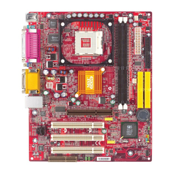
Page 10: Mainboard Layout
Line-Out Line-In ATX12V T: LAN jack B: USB ports Realtek 8201BL JCD1 JSP1 Codec JAUD1 651M-V Series (MS-7005) v2.X Micro ATX Mainboard CPUFAN1 SiS 651 AGP Slot PCI Slot 1 JUSB2 962L PCI Slot 2 PCI Slot 3 JUSB1 Winbond... -
Page 11: Chapter 2. Hardware Setup
Chapter 2. Hardware Setup Hardware Setup This chapter tells you how to install the CPU, memory modules, and expansion cards, as well as how to setup the jumpers on the mainboard. It also provides the instructions on connecting the periph- eral devices, such as the mouse, keyboard, etc. -
Page 12: Quick Components Guide
MS-7005 Micro ATX Mainboard Quick Components Guide ATX12V, p.2-9 Back Panel I/O, p.2-10 AGP Slot, p.2-20 JSP1, p.2-18 JCD1, p.2-16 PCI Slots, p.2-20 JAUD1, p.2-16 CPU, p.2-3 JFP2, p.2-17 JUSB2, p.2-18 JUSB1, p.2-18 DDR DIMMs, p.2-7 CPUFAN1, p.2-14 CONN1, p.2-9 FDD1, p.2-14 SYSFAN1, p.2-14 IDE1, IDE2,... -
Page 13: Central Processing Unit: Cpu
If you do not find the heat sink and cooling fan, contact your dealer to purchase and install them before turning on the computer. For the latest information about CPU, please visit http://www.msi.com.tw/ program/products/mainboard/mbd/pro_mbd_cpu_support.php Example of CPU Core Speed Derivation Procedure... -
Page 14: Cpu Installation Procedures For Socket 478
MS-7005 Micro ATX Mainboard CPU Installation Procedures for Socket 478 1. Please turn off the power and unplug the power cord before installing the CPU. 2. Pull the lever sideways away from the socket. Make sure to raise the lever up to a 90-de- gree angle. -
Page 15: Installing The Cpu Fan
CPU cooling fan and heatsink on top of the CPU. Follow the instructions below to install the Heatsink/Fan: 1. Locate the CPU and its retention mechanism on the motherboard. retention mechanism 3. Mount the fan on top of the heatsink. - Page 16 MS-7005 Micro ATX Mainboard 5. Connect the fan power cable from the mounted fan to the 3-pin fan power connector on the board. fan power cable NOTES...
-
Page 17: Memory
The mainboard provides two 184-pin unbuffered DDR200/DDR266/DDR333 DDR SDRAM, and supports the memory size up to 2GB. To operate properly, at least one DIMM module must be installed. For the uplated supporting memory modules, please visit http://www.msi. com.tw/program/products/mainboard/mbd/pro_mbd_trp_list.php. Introduction to DDR SDRAM DDR (Double Data Rate) SDRAM is similar to conventional SDRAM, but dou- bles the rate by transferring data twice per cycle. -
Page 18: Ddr Module Combination
3. The plastic clip at each side of the DIMM slot will automatically close. MSI Reminds You... You can barely see the golden finger if the module is properly inserted in the socket. -
Page 19: Power Supply
The mainboard supports ATX power supply for the power system. Before inserting the power supply connector, always make sure that all components are installed properly to ensure that no damage will be caused. ATX 20-Pin Power Connector: CONN1 This connector allows you to connect to an ATX power supply. To connect to the ATX power supply, make sure the plug of the power supply is inserted in the proper orientation and the pins are aligned. -
Page 20: Back Panel
MS-7005 Micro ATX Mainboard The back panel provides the following connectors: Parallel Mouse COMA Keyboard Mouse Connector The mainboard provides a standard PS/2 ® ing a PS/2 mouse. You can plug a PS/2 connector location and pin assignments are as follows: PS/2 Mouse (6-pin Female) Keyboard Connector... -
Page 21: Serial Port Connectors: Coma
Serial Port Connectors: COMA The mainboard offers one 9-pin male DIN connector as serial port COM A. This port is 16550A high speed communication ports that send/receive 16 bytes FIFOs. You can attach a serial mouse or other serial device directly to it. 1 2 3 4 5 6 7 8 9 9-Pin Male DIN Connector... -
Page 22: Rj-45 Lan Jack
CD player, Tape player, or other audio devices. Mic is a connector for microphones. 1/8” Stereo Audio Connectors MSI Reminds You... For advanced audio application, Realtek ALC 655 is provided to offer support for 6-channel audio operation and can turn rear audio connectors from 2-channel to 4-/6-channel audio. -
Page 23: Midi/Joystick Connector
Midi/Joystick Connector You can connect a joystick or game pad to this connector. Parallel Port Connector: LPT1 The mainboard provides a 25-pin female centronic connector as LPT. A parallel port is a standard printer port that supports Enhanced Parallel Port (EPP) and Extended Capabilities Parallel Port (ECP) mode. -
Page 24: Connectors
If the mainboard has a System Hardware Monitor chipset on-board, you must use a specially designed fan with speed sensor to take advantage of the CPU fan control. CPUFAN1 MSI Reminds You... 1. Always consult the vendors for proper CPU cooling fan. 2. Please refer to the recommend CPU fans at Intel 3. -
Page 25: Hard Disk Connectors: Ide1 & Ide2
IDE2 (Secondary IDE Connector) IDE2 can also connect a Master and a Slave drive. MSI Reminds You... If you install two hard disks on cable, you must configure the second drive to Slave mode by setting its jumper. Refer to the hard disk documentation supplied by hard disk vendors for jumper setting instructions. -
Page 26: Cd-In Connector: Jcd1
HP_ON AUD_FPOUT_L AUD_RET_L MSI Reminds You... If you don’t want to connect to the front audio header, pins 5 & 6, 9 & 10 have to be jumpered in order to have signal output directed to the rear audio ports. Otherwise, the Line-Out connector on the back panel will not function. -
Page 27: Chassis Intrusion Switch Connector: Jci1
Chassis Intrusion Switch Connector: JCI1 This connector is connected to 2-pin connector chassis switch. If the Chassis is open, the switch will be short. The system will record this status. To clear the warning, you must enter the BIOS setting and clear the status. Front Panel Connectors: JFP1 &... -
Page 28: Front Usb Connectors: Jusb1/Jusb2
MS-7005 Micro ATX Mainboard Front USB Connectors: JUSB1/JUSB2 The mainboard provides two USB 2.0 pin headers JUSB1 & JUSB2 that are compliant with Intel ® I/O Connectivity Design Guide. USB 2.0 technology increases data transfer rate up to a maximum throughput of 480Mbps, which is 40 times faster than USB 1.1, and is ideal for connecting high-speed USB interface peripherals such as USB HDD, digital cameras, MP3 players, printers, modems and the like. -
Page 29: Jumpers
The motherboard provides the following jumpers for you to set the computer’s function. This section will explain how to change your motherboard’s function through the use of jumpers. Clear CMOS Jumper: JBAT1 There is a CMOS RAM on board that has a power supply from external battery to keep the data of system configuration. -
Page 30: Slots
MS-7005 Micro ATX Mainboard The motherboard provides one AGP slot and five 32-bit PCI bus slots. AGP (Accelerated Graphics Port) Slot The AGP slot allows you to insert the AGP graphics card. AGP is an interface specification designed for the throughput demands of 3D graphics. It introduces a 66MHz, 32-bit channel for the graphics controller to directly access main memory. -
Page 31: Chapter 3. Bios Setup
SETUP. You want to change the default settings for customized features. MSI Reminds You... 1. The items under each BIOS category described in this chapter are under continuous update for better system performance. -
Page 32: Entering Setup
MS-7005 Micro ATX Mainboard Power on the computer and the system will start POST (Power On Self Test) process. When the message below appears on the screen, press <DEL> key to enter Setup. P r e s s If the message disappears before you respond and you still wish to enter Setup, restart the system by turning it OFF and On or pressing the RESET button. -
Page 33: The Main Menu
BIOS Setup The Main Menu Once you enter Award ® BIOS CMOS Setup Utility, the Main Menu (figure below) will appear on the screen. The Main Menu allows you to select from twelve setup functions and two exit choices. Use arrow keys to select among the items and press <Enter>... - Page 34 MS-7005 Micro ATX Mainboard Load Optimized Defaults Use this menu to load factory default settings into the BIOS for stable system perfor- mance operations. Set Supervisor Password Use this menu to set Supervisor Password. Set User Password Use this menu to set User Password. Save &...
-
Page 35: Standard Cmos Features
Standard CMOS Features The items in Standard CMOS Features Menu are divided into 11 categories. Each category includes no, one or more than one setup items. Use the arrow keys to highlight the item and then use the <PgUp> or <PgDn> keys to select the value you want in each item. - Page 36 MS-7005 Micro ATX Mainboard Drive A/B This item allows you to set the type of floppy drives installed. Available options: [None], [360K, 5.25 in.], [1.2M, 5.25 in.], [720K, 3.5 in.], [1.44M, 3.5 in.], [2.88M, 3.5 in]. Floppy 3 Mode Support The item allows you to set the Floppy 3 Mode.
-
Page 37: Advanced Bios Features
The items allow you to set the sequence of boot devices where BIOS attempts to load the disk operating system. MSI Reminds You... 1. Available settings for 1st/2nd/3rd Boot Device vary depending on the bootable devices you have installed. For example, if you did not install a floppy drive, the setting [Floppy] does not show up. - Page 38 [Enabled] will increase the system performance. Settings: [Enabled], [Disabled]. Please disable this item if your operating system doesn’t support HT Function, or unreliability and instability may occur. MSI Reminds You... Enabling the functionality of Hyper-Threading Technology for your com- puter system requires ALL of the following platform Components: *CPU: An Intel ®...
- Page 39 Security Option This specifies the type of BIOS password protection that is implemented. Settings are described below: Option Description [Setup] The password prompt appears only when end users try to run Setup. [System] A password prompt appears every time when the computer is powered on or when end users try to run Setup.
-
Page 40: Advanced Chipset Features
MS-7005 Micro ATX Mainboard Advanced Chipset Features MSI Reminds You... Change these settings only if you are familiar with the chipset. Advanced DRAM Control 1 Press <Enter> and the following sub-menu appears: System Performance This setting particularly provided by SiS gives the proper suggestion for user to set timing. - Page 41 BIOS Setup AGP Aperture Size This setting controls just how much system RAM can be allocated to AGP for video purposes. The aperture is a portion of the PCI memory address range dedicated to graphics memory address space. Host cycles that hit the aperture range are for- warded to the AGP without any translation.
-
Page 42: Integrated Peripherals
MS-7005 Micro ATX Mainboard Integrated Peripherals SiS OnChip IDE Device Press <Enter> and the following sub-menu appears: Internal PCI/IDE The field specifies the internal primary and secondary PCI/IDE controllers. Settings: [Disabled], [Primary], [Secondary], [Both]. IDE Primary/Secondary Master/Slave PIO The four IDE PIO (Programmed Input/Output) fields let you set a PIO mode (0-4) for each of the four IDE devices that the onboard IDE interface supports. - Page 43 SiS USB Controller Select Enabled if your system contains a Universal Serial Bus (USB) controller and you have USB peripherals. Settings: [Enabled], [Disabled]. USB 2.0 Supports This item is used to enable/disable the USB 2.0 Support. Settings: [Enabled], [Disabled]. USB Keyboard/Mouse Support Set to [Enabled] if you need to use a USB keyboard/mouse in the operating system that does not support or does not have any USB driver installed, such as DOS and SCO Unix.
- Page 44 MS-7005 Micro ATX Mainboard Onboard Serial Port 1 The item specify the base I/O port address and IRQ for the onboard Serial Port A (COM A). Selecting [Auto] allows BIOS to automatically determine the correct base I/O port address. Settings: [Disabled], [3F8/IRQ4], [2F8/IRQ3], [3E8/IRQ4], [2E8/IRQ3], [Auto].
-
Page 45: Power Management Setup
Power Management Setup Sleep State This item specifies the power saving modes for ACPI function. Options are: [S1/POS] The S1 sleep mode is a low power state. In this state, no system context is lost (CPU or chipset) and hardware main- tains all system context. - Page 46 PM Wake Up Events Press <Enter> and the following sub-menu appears: MSI Reminds You... S3-related functions described in this section are available only when your BIOS supports S3 sleep mode. IRQ [3-7, 9-15], NMI; IRQ 8 Break Suspend...
- Page 47 PS2KB Wakeup From S3/S4/S5 This setting allows you to wake up the system from S3/S4/S5 states with the options of [Any Key], [Hot Key] and [Password] (max. 8 numbers). PS2MS Wakeup From S3/S4/S5 This controls how the PS/2 mouse can power on the system. Settings: [Click], [Move &...
-
Page 48: Pnp/Pci Configurations
MS-7005 Micro ATX Mainboard PNP/PCI Configurations This section describes configuring the PCI bus system and PnP (Plug & Play) feature. PCI, or Peripheral Component Interconnect, is a system which allows I/O devices to operate at speeds nearing the speed the CPU itself uses when communi- cating with its special components. - Page 49 IRQ Resources list IRQ 3/4/5/7/9/10/11/12/14/15 for users to set each IRQ a type depending on the type of device using the IRQ. Settings are: [PCI Device] For Plug & Play compatible devices designed for PCI bus architecture. [Reserved] The IRQ will be reserved for further request. PCI/VGA Palette Snoop When set to [Enabled], multiple VGA devices operating on different buses can handle data from the CPU on each set of palette registers on every video device.
-
Page 50: Pc Health Status
MS-7005 Micro ATX Mainboard PC Health Status This section shows the status of your CPU, fan, overall system status, etc. Monitor function is available only if there is hardware monitoring mechanism onboard. Case Open Warning The field enables or disables the feature of recording the chassis intrusion status and issuing a warning message if the chassis is once opened. -
Page 51: Frequency/Voltage Control
(EMI). Settings: [Enabled], [Disabled]. Spread Spectrum When the motherboard’s clock generator pulses, the extreme values (spikes) of the pulses creates EMI (Electromagnetic Interference). The Spread Spectrum function reduces the EMI generated by modulating the pulses so that the spikes of the pulses are reduced to flatter curves. -
Page 52: Load Fail-Safe/Optimized Defaults
MS-7005 Micro ATX Mainboard Load Fail-Safe/Optimized Defaults The two options on the main menu allow users to restore all of the BIOS settings to the default Fail-Safe or Optimized values. The Optimized Defaults are the default values set by the mainboard manufacturer specifically for optimal performance of the mainboard. -
Page 53: Set Supervisor/User Password
Option is set to [System], the password is required both at boot and at entry to Setup. If set to [Setup], password prompt only occurs when you try to enter Setup. MSI Reminds You... About Supervisor Password & User Password:...