
Related Manuals for MSI 648 Max


Summary of Contents for MSI 648 Max
- Page 1 648 Max MICRO-STAR INTERNATIONAL MS-6585 (v1.X) ATX Mainboard Version 1.1 G52-M6585X6...
- Page 2 Manual Rev: 1.1 Release Date: January 2003 FCC-B Radio Frequency Interference Statement This equipment has been tested and found to comply with the limits for a class B digital device, pursuant to part 15 of the FCC rules. These limits are designed to provide reasonable protection against harmful interference when the equip- ment is operated in a commercial environment.
-
Page 3: Copyright Notice
Copyright Notice The material in this document is the intellectual property of MICRO-STAR INTERNATIONAL. We take every care in the preparation of this document, but no guarantee is given as to the correctness of its contents. Our products are under continual improvement and we reserve the right to make changes without notice. -
Page 4: Safety Instructions
Safety Instructions Read the safety instructions carefully. Save this User’s Guide for possible use later. Keep this equipment away from humidity. Lay this equipment on a stable and flat surface before setting it up. The openings on the enclosure are used for air convection and to prevent the equipment from overheating. -
Page 5: Table Of Contents
Mainboard Specification ............1-2 Mainboard Layout ..............1-5 Quick Components Guide ............1-5 Fuzzy Logic™ 4 ..............1-6 MSI Special Features ..............1-6 Live BIOS™/Live Driver™ ............ 1-7 Live Monitor™ ..............1-8 S-Bracket (Optional) ............1-9 D-Bracket™ 2 (Optional) ........... 1-10 PC Alert™... - Page 6 RJ-45 LAN Jack ..............2-10 Audio Port Connectors ............2-11 Parallel Port Connector: LPT1 ........... 2-13 Connectors ................2-13 Floppy Disk Drive Connector: FDD1 ........2-13 Hard Disk Connectors: IDE1 & IDE2 ......... 2-15 CD-In Connector: JCD1 ............. 2-15 Fan Power Connectors: CPUFA/SYSFA ......2-17 Front Panel Connectors: JFP1 &...
- Page 7 PNP/PCI Configuration ............3-19 Integrated Peripherals ............. 3-23 PC Health Status ..............3-25 Frequency/Voltage Control ............3-27 Set Supervisor/User Password ..........3-29 Load Optimal/High Performance Defaults ........ 3-31 Save & Exit Setup ..............3-31 Exit Without Saving ..............3-32 Appendix: Using 4- or 6-Channel Audio Function ..... A-1 Installing the Audio Driver ............
-
Page 8: Chapter 1. Getting Started
648 Max is a superior computer motherboard based on SiS648 and SiS963 chipsets for optimal system efficiency. Designed to fit the advanced Intel ® Pentium 4 processors in the 478 pin package, the 648 Max delivers a high ® performance and professional desktop platform solution. TOPICS... -
Page 9: Mainboard Specification
Chapter 1 Mainboard Specification Socket 478 for P4 processors (Willimate 478 and Northwood 478) with 400/ 533 MHz (100/133MHz QDIR) Core frequency from 1.3 GHz to 3.06 GHz and up Chipset 648/648 B Stepping (839 pin BGA) ® - Supports Intel Pentium 4 processors with data transfer rate up to 533 MHz - Supports 64-bit high performance DDR 333+ / DDR 333 / DDR 266 memory controller - Supports AGP 8X/4X interface at 0.8v or 4x at 1.5v with fast write transaction... - Page 10 Getting Started - 1 parallel port supports SPP/EPP/ECP mode. - 6 USB ports (Rear * 4/ Front * 2). - 1 IrDA connector for SIR. - 1 RJ-45 LAN jack (optional). - 1 audio port. - 1 Bluetooth pin header - 1 S-Bracket pin header.
-
Page 11: Mainboard Layout
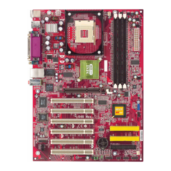
PCI Slot 2 BIOS PCI Slot 3 JBT1 IDE 1 PCI Slot 4 Codec IDE 2 PCI Slot 5 JSP1 BATT FDD 1 JCD1 PCI Slot 6 SYSFA JBAT1 JDB1 JIR1 JFP2 JFP1 JAUD1 648 Max (MS-6585 v1.X) ATX Mainboard... -
Page 12: Quick Components Guide
Getting Started Quick Components Guide Component Function Reference CONN1/JPW1 Power connectors See p. 2-7 JKBMS1 Mouse connector See p. 2-8 JKBMS1 Keyboard connector See p. 2-9 USB 2.0 Connectors Connecting to USB devices See p. 2-9 COMA & COMB Serial port connectors See p. -
Page 13: Fuzzy Logic™ 4
After rebooting, click Turbo to apply the test result. Click Default to restore the default values. Features: MSI Logo links to the MSI Web site CPU Speed allows users to adjust the CPU speed through CPU Multiplier and FSB... - Page 14 Getting Started S-Bracket (Optional) S-Bracket is a bracket which provides 2 SPDIF jacks for digital audio transmission and 2 analog Line-Out connectors for additional 4-channel ana- log audio output. With the S-Bracket, your system will be able to perform 6- channel audio operation for wonderful surround sound effect, or connect to Sony &...
-
Page 15: Live Bios™/Live Driver
Web site. To use the function, you need to install the “MSI Live Update Series 2” application. After installation, the “MSI Live Update Series 2” icon (as shown on the right) will appear on the screen. Double click the “MSI Live Update Series 2” icon, and the following screen will appear: Five buttons are placed on the leftmost pane of the screen. -
Page 16: Live Monitor
Live Monitor™ The Live Monitor™ is a tool used to schedule the search for the latest BIOS/drivers version on the MSI Web site. To use the function, you need to install the “MSI Live Update Series 2” application. After the installation, the “MSI Live Monitor” icon (as shown on the right) will appear on the screen. - Page 17 Chapter 1 PC Alert™ 4 The PC Alert 4 is a utility you can find in the CD-ROM disk. The utility is just like your PC doctor that can detect the following PC hardware status during real time operation: monitor CPU & system temperatures monitor fan speeds monitor system voltages If one of the items above is abnormal, the program main screen will be...
- Page 18 CPU and chipset. Right-click the mouse to select the skin you want to switch to. C u t e MSI Reminds You... The new feature COOLER XP will work only if your mainboard supports AMD Athlon XP CPU.
-
Page 19: D-Bracket™ 2 (Optional)
Chapter 1 D-Bracket™ 2 (Optional) D-Bracket™ 2 is a USB bracket integrating four Diagnostic LEDs, which use graphic signal display to help users understand their system. The LEDs provide up to 16 combinations of signals to debug the system. The 4 LEDs can detect all problems that fail the system, such as VGA, RAM or other failures. -
Page 20: Getting Started
Getting Started D-Bracket™ 2 Description Processor Initialization - This will show information regarding the processor (like brand name, system bus, etc…) Testing RTC (Real Time Clock) Initializing Video Interface - This will start detecting CPU clock, checking type of video onboard. -
Page 21: Chapter 2. Hardware Setup
Hardware Setup Chapter 2. Hardware Setup Hardware Setup This chapter provides you with the information about hardware setup procedures. While doing the installation, be careful in holding the components and follow the installation procedures. For some components, if you install in the wrong orientation, the components will not work properly. -
Page 22: Cpu Installation Procedures For Socket 478
Chapter 2 CPU Installation Procedures for Socket 478 Open Lever Please turn off the power and unplug the power cord before installing the CPU. Sliding 90 degree Plate Pull the lever sideways away from the socket. Make sure to raise the lever up to a 90- degree angle. -
Page 23: Installing The Cpu Fan
Hardware Setup Installing the CPU Fan As processor technology pushes to faster speeds and higher performance, thermal management becomes increasingly important. To dissi- pate heat, you need to attach the CPU cooling fan and heatsink on top of the CPU. Follow the instructions below to install the Heatsink/Fan: Locate the CPU and its retention Position the heatsink onto the reten- mechanism on the motherboard. -
Page 24: Cpu Core Speed Derivation Procedure
Chapter 2 C o nnec t t h e f a n p o w e r c a b le f r o m t h e m o unt e d f a n t o t h e 3-p i n f a n p o w e r c o nnec t o r on t h e boa r d . -
Page 25: Memory
Hardware Setup Memory The mainboard provides 3 slots for 184-pin DDR DIMM (Double In-Line Memory Module) modules and supports the memory size up to 3 GB without ECC. You can install DDR 200, DDR 266, DDR 333 MHz and up PC 133 modules on the DDR DIMM slots (DDR 1~3). -
Page 26: Ddr Dimm Module Combination
Chapter 2 DDR DIMM Module Combination Install at least one DIMM module on the slots. Memory modules can be installed on the slots in any order. You can install either single- or double- sided modules to meet your own needs. Memory modules can be installed in any combination as follows: Slot Memory Module... -
Page 27: Power Supply
Hardware Setup Power Supply The mainboard supports ATX power supply for the power system. Be- fore inserting the power supply connector, always make sure that all compo- nents are installed properly to ensure that no damage will be caused. ATX 20-Pin Power Connector: CONN1 This connector allows you to connect to an ATX power supply. -
Page 28: Back Panel
Chapter 2 Back Panel The Back Panel provides the following connectors: Parallel (Optional) Mouse USB Ports L-in Keyboard USB Ports COM A COM B L-out Mouse Connector: JKBMS1 ® The mainboard provides a standard PS/2 mouse mini DIN connector for ®... -
Page 29: Keyboard Connector: Jkbms1
Hardware Setup Keyboard Connector: JKBMS1 ® The mainboard provides a standard PS/2 keyboard mini DIN connector ® ® for attaching a PS/2 keyboard. You can plug a PS/2 keyboard directly into this connector. Pin Definition SIGNAL DESCRIPTION Keyboard DATA Keyboard DATA No connection Ground Keyboard Clock... -
Page 30: Serial Port Connectors: Coma & Comb
Chapter 2 Serial Port Connectors: COMA & COMB The mainboard offers two 9-pin connectors as serial port COM A & COMB. The ports are 16550A high speed communication ports that send/ receive 16 bytes FIFOs. You can attach a serial mouse or other serial devices directly to the connectors. -
Page 31: Audio Port Connectors
Hardware Setup Audio Port Connectors Line Out is a connector for Speakers or Headphones. Line In is used for external CD player, Tape player, or other audio devices. Mic is a connector for microphones. Line In 1/8” Stereo Audio Connectors Line Out TIP: The mainboard offers support for 6-channel audio operation... -
Page 32: Parallel Port Connector: Lpt1
Chapter 2 Parallel Port Connector: LPT1 The mainboard provides a 25-pin female centronic connector as LPT. A parallel port is a standard printer port that supports Enhanced Parallel Port (EPP) and Extended Capabilities Parallel Port (ECP) mode. Pin Definition SIGNAL DESCRIPTION STROBE Strobe... -
Page 33: Connectors
Hardware Setup Connectors The mainboard provides connectors to connect to FDD, IDE HDD, case, modem, LAN, USB Ports, IR module and CPU/System FAN. Floppy Disk Drive Connector: FDD1 The mainboard provides a standard floppy disk drive connector that supports 360K, 720K, 1.2M, 1.44M and 2.88M floppy disk types. FDD1 2-13... -
Page 34: Hard Disk Connectors: Ide1 & Ide2
Chapter 2 Hard Disk Connectors: IDE1 & IDE2 The mainboard has a 32-bit Enhanced PCI IDE and Ultra DMA 66/100/ 133 controller that provides PIO mode 0~4, Bus Master, and Ultra DMA66/100/ 133 function. You can connect up to four hard disk drives, CD-ROM, 120MB Floppy (reserved for future BIOS) and other devices. -
Page 35: Cd-In Connector: Jcd1
Hardware Setup CD-In Connector: JCD1 The connector is for CD-ROM audio connector. JCD1 2-15... -
Page 36: Fan Power Connectors: Cpufa/Sysfa
Chapter 2 Fan Power Connectors: CPUFA/SYSFA The CPUFA (processor fan) & SYSFA (system fan) support system cool- ing fan with +12V. It supports three-pin head connector. When connecting the wire to the connectors, always take note that the red wire is the positive and should be connected to the +12V, the black wire is Ground and should be connected to GND. -
Page 37: Front Panel Connectors: Jfp1 & Jfp2
Hardware Setup Front Panel Connectors: JFP1 & JFP2 The mainboard provides front panel connectors for electrical connection to the front panel switches and LEDs. Users can choose either the JFP1 or the ® JFP2 depending on their needs. JFP1 is compliant with Intel Front Panel I/O Connectivity Design Guide. - Page 38 Chapter 2 Front Panel Audio Connector: JAUD1 You can connect an optional audio connector to the Front Panel Audio ® Header. JAUD1 is compliant with Intel Front Panel I/O Connectivity Design Guide. JAUD1 Pin Definition SIGNAL DESCRIPTION AUD_MIC Front panel microphone input signal AUD_GND Ground used by analog audio circuits AUD_MIC_BIAS...
-
Page 39: Irda Infrared Module Header: Jir1
Hardware Setup IrDA Infrared Module Header: JIR1 This connector allows you to connect to IrDA Infrared modules and is compliant with Intel® Front Panel I/O Connectivity Design Guide. You must configure the setting through the BIOS setup to use the IR function. JIR1 Pin Definition Signal IRTX... -
Page 40: D-Bracket™ 2 Connector: Jdb1 (Optional)
Chapter 2 D-Bracket™ 2 Connector: JDB1 (Optional) The mainboard comes with a JDB1 connector for you to connect to D- Bracket™ 2. D-Bracket™ 2 is a USB Bracket that supports both USB1.1 & 2.0 specification. It integrates four LEDs and allows users to identify system problem through 16 various combinations of LED signals. -
Page 41: Bluetooth Connector: Jbt1
Hardware Setup Bluetooth Connector: JBT1 This connector is used to connect a bluetooth module for wireless connection. JBT1 JBT1 Pin Definition SIGNAL SIGNAL 5VDUAL 3VDUAL D+ (USB signal) D- (USB signal) Note: Because the bluetooth connector shares the USB interface with blue- colored USB2.0 connector, the bottommost USB2.0 port will not function when you attach a bluetooth module to this connector. -
Page 42: S-Bracket Connector: Jsp1
Chapter 2 S-Bracket Connector: JSP1 The connector allows you to connect a S-Bracket for Sony & Philips Digital Interface (SPDIF). The S-Bracket offers 2 SPDIF jacks for digital audio transmission (one for optical fiber connection and the other for coaxial), and 2 analog Line-Out jacks for 4-channel audio output. -
Page 43: Hardware Setup
Hardware Setup JSP1 Pin Definition SIGNAL DESCRIPTION SIGNAL DESCRIPTION VCC5 VCC 5V VDD3 VDD 3.3V SPDFO S/PDIF output (No Pin) Ground SPDFI S/PDIF input LFE-OUT Audio bass output SOUT-R Audio right surrounding output CET-OUT Audio center output SOUT-L Audio left surrounding output Ground Ground S-Bracket... -
Page 44: Front Usb 2.0 Connector: Jusb2
Chapter 2 Front USB 2.0 Connector: JUSB2 The mainboard provides one USB 2.0 pin headers USB2. USB 2.0 technology increases data transfer rate up to a maximum throughput of 480Mbps, which is 40 times faster than USB 1.1, and is ideal for connecting high-speed USB interface peripherals such as USB HDD, digital cameras, ®... -
Page 45: Jumpers
Hardware Setup Jumpers The motherboard provides one jumper for you to set the computer’s function. This section will explain how to change your motherboard’s function through the use of the jumper. Clear CMOS Jumper: JBAT1 There is a CMOS RAM on board that has a power supply from external battery to keep the data of system configuration. -
Page 46: Agp (Accelerated Graphics Port) Slot
Chapter 2 Slots The motherboard provides six 32-bit Master PCI bus slots and one AGP slot. AGP Slot PCI Slots AGP (Accelerated Graphics Port) Slot The AGP slot allows you to insert the AGP graphics card. AGP is an interface specification designed for the throughput demands of 3D graphics. It introduces a 66MHz, 32-bit channel for the graphics controller to directly access main memory. -
Page 47: Pci Interrupt Request Routing
Hardware Setup PCI Interrupt Request Routing The IRQ, abbreviation of interrupt request line and pronounced I-R-Q, are hardware lines over which devices can send interrupt signals to the microprocessor. The PCI IRQ pins are typically connected to the PCI bus INT A# ~ INT D# pins as follows: Order 1 Order 2... -
Page 48: Chapter 3. Ami® Bios Setup
® BIOS Setup ® Chapter 4. AMI BIOS Setup ® BIOS Setup ® If your motherboard comes with the AMI BIOS ROM, read this chap- ® ® ter for an overview of the AMI BIOS settings. AMI BIOS ROM provides a Setup utility for users to modify the basic system configuration. -
Page 49: Entering Setup
Chapter 3 Entering Setup Power on the computer and the system will start POST (Power On Self Test) process. When the message below appears on the screen, press <DEL> key to enter Setup. DEL:Setup F11:Boot Menu F12:Network boot TAB:Logo If the message disappears before you respond and you still wish to enter Setup, restart the system by turning it OFF and On or pressing the RESET button. -
Page 50: Control Keys
® BIOS Setup Control Keys < Move to the previous item < Move to the next item < Move to the item in the left hand < Move to the item in the right hand <Enter> Select the item <Esc> Jumps to the Exit menu or returns to the main menu from a submenu <+/PU>... -
Page 51: Getting Help
Chapter 3 Getting Help After entering the Setup utility, the first screen you see is the Main Menu. Main Menu The main menu displays the setup categories the BIOS supplies. You can use the arrow keys ( to select the item. The on-line description for the selected setup category is displayed on the bottom of the screen. -
Page 52: The Main Menu
® BIOS Setup The Main Menu Once you enter AMIBIOS SIMPLE SETUP UTILITY, the Main Menu will appear on the screen. The Main Menu displays twelve configurable functions and two exit choices. Use arrow keys to move among the items and press <Enter> to enter the sub-menu. - Page 53 Chapter 3 Integrated Peripherals Use this menu to specify your settings for integrated peripherals. PC Health Status This entry shows your PC’s current status. Frequency/Voltage Control Use this menu to specify your settings for frequency/voltage control. Set Supervisor Password Use this menu to set Supervisor Password. Set User Password Use this menu to set User Password.
-
Page 54: Standard Cmos Setup
® BIOS Setup Standard CMOS Setup The items inside STANDARD CMOS SETUP menu are divided into 9 catego- ries. Each category includes none, one or more setup items. Use the arrow keys to highlight the item you want to modify and use the <PgUp> or <PgDn> key to switch to the value you prefer. - Page 55 Chapter 3 Pri Master/Pri Slave/Sec Master/Sec Slave Press PgUp/<+> or PgDn/<-> to select the hard disk drive type. The specifica- tion of hard disk drive will show up on the right hand according to your selection. Type Type of the device. Cylinders Number of cylinders.
-
Page 56: Advanced Bios Features
® BIOS Setup Advanced BIOS Features Quick Boot Setting the item to Enabled allows the system to boot within 5 seconds by skiping some check items. Settings: Enabled and Disabled. Full Screen LOGO Show This item enables you to show the company logo on the bootup screen. Settings are: BIOS Shows the POST messages at boot. - Page 57 Chapter 3 1st/2nd/3rd Boot Device The items allow you to set the sequence of boot devices where AMIBIOS attempts to load the operating system. The settings are: IDE-0 The system will boot from the first HDD. IDE-1 The system will boot from the second HDD. IDE-2 The system will boot from the third HDD.
- Page 58 ® BIOS Setup Boot Other Devices Setting the option to Yes allows the system to try to boot from other devices if the system fails to boot from the 1st/2nd/3rd boot device. Hard Disk S.M.A.R.T. This allows you to activate the S.M.A.R.T. (Self-Monitoring Analysis & Reporting Technology) capability for the hard disks.
- Page 59 Chapter 3 Security Option This specifies the type of BIOS password protection that is implemented. Setting options are described below. Option Description Setup The password prompt appears only when end users try to run Setup. Always A password prompt appears every time when the com- puter is powered on or when end users try to run Setup.
- Page 60 ® BIOS Setup APIC Function This field is used to enable or disable the APIC (Advanced Programmable Interrupt Controller). Due to compliance to PC2001 design guide, the system is able to run in APIC mode. Enabling APIC mode will expand available IRQs resources for the system.
-
Page 61: Advanced Chipset Features
Chapter 3 Advanced Chipset Features Note: Change these settings only if you are familiar with the chipset. CAS Latency The field controls the CAS latency, which determines the timing delay before SDRAM starts a read command after receiving it. Setting options: By SPD, 3T, 2.5T, 2T. - Page 62 ® BIOS Setup MA 1T/2T Select This setting controls the SDRAM command rate. Selecting Auto allows SDRAM signal controller to run at 1T (T=clock cycles) rate. Selecting MA 1T makes SDRAM signal controller run at 2T rate. 1T is faster than 2T. Setting options: Auto, MA2T, MA1T.
-
Page 63: Power Management Setup
Chapter 3 Power Management Setup IPCA Function This item is to activate the ACPI (Advanced Configuration and Power Man- agement Interface) Function. If your operating system is ACPI-aware, such as Windows 98SE/2000/ME, select Yes. Settings: Enabled and Disabled. Sleep State This item specifies the power saving modes for ACPI function. - Page 64 ® BIOS Setup Initalize VGA BIOS By S3 Selecting Enabled will make BIOS call VGA BIOS to initialize the VGA card when system wakes up (resume) from S3 state. The system resume time is shortened if you disable the function, but system will need AGP driver to initialize the card.
- Page 65 Chapter 3 Wake Up On PME#, Resume on PS2 Mouse From S3 These fields specify whether the system will be awakened from power saving modes when activity or input signal of the specified hardware peripheral or component is detected. Settings: Enabled, Disabled. PS2 MOUSE Wake Select Mode When Resume on PS2 Mouse From S3 is set to Enabled, you may use this item to specify the PS2 mouse wake-up mode.
-
Page 66: Pnp/Pci Configuration
® BIOS Setup PNP/PCI Configuration This section describes configuring the PCI bus system and PnP (Plug & Play) feature. PCI, or Peripheral Component Interconnect, is a system which allows I/O devices to operate at speeds nearing the speed the CPU itself uses when communicating with its special components. - Page 67 Chapter 3 PCI Slot 1/5 IRQ Priority, PCI Slot 2/6 IRQ Priority, PCI Slot 3 IRQ Priority, PCI Slot 4 IRQ Priority This item specifies the IRQ line for each PCI slot. Settings: 3, 4, 5, 7, 9, 10, 11 and Auto.
- Page 68 ® BIOS Setup DMA Channel 0/1/3/5/6/7 These items specify the bus that the system DMA (Direct Memory Access) channel is used. The settings determine if AMIBIOS should remove a DMA from the available DMAs passed to devices that are configurable by the system BIOS.
-
Page 69: Integrated Peripherals
Chapter 3 Integrated Peripherals USB Function This setting is used to enable/disable the onboard USB controllers. Settings: Enabled, Disabled. USB 2.0 Supports This item is used to enable or disable the USB 2.0 supports. Settings: Enabled, Disabled. USB Legacy Support This item is used to enable or disable the USB KB/MOUSE/FDD legacy supports. - Page 70 ® BIOS Setup OnBoard LAN Controller This item is used to enable or disable the onboard LAN controllers. Settings: Enabled, Disabled. OnBoard PCI IDE This setting controls the onboard PCI IDE controllers. Setting options: Disabled, Primiary, Secondary, Both. Set Super I/O Press <Enter>...
- Page 71 Chapter 3 IR Pin Select Set to IRRX/IRTX when using an internal IR module connected to the IR connector. Set to SINB/SOUTB. when connecting an IR adapter to COM 2. OnBoard Parallel Port These items specify the base I/O port addresses of the onboard parallel port. Selecting Auto allows AMIBIOS to automatically determine the correct base I/ O port address.
-
Page 72: Pc Health Status
® BIOS Setup PC Health Status This section shows the status of your CPU, fan, warning for overall system status. System/CPU Temperature, System/CPU Fan Speed, Vcore, +3.3V, +5.0V, +12V, -12V, Battery, -5.0V These items display the current status of all of the monitored hardware de- vices/components such as system voltages, temperatures and fan speeds. -
Page 73: Frequency/Voltage Control
Chapter 3 Frequency/Voltage Control This section describes how to set the Chassis Intrusion feature, CPU FSB frequency, monitor the current hardwae status including CPU/system temperatures, CPU/System Fan speeds, Vcore etc. Monitor function is available only if there is hardware monitoring mechanism onboard. Spread Spectrum When the motherboard clock generator pulses, the extreme values (spikes) of the pulses creates EMI (Electromagnetic Interference). - Page 74 ® BIOS Setup CPU Ratio This setting controls the multiplier that is used to determine the internal clock speed of the processor relative to the external or motherboard clock speed. CPU/DRAM Frequency Ratio This setting controls the ratio of CPU FSB Clock & DRAM Frequency to enable the CPU &...
- Page 75 Chapter 3 CPU Vcore Adjust The setting allows you to adjust the CPU Vcore voltage. Available options: For Willimate 1.725, Auto, 1.775, 1.800, 1.825 For Northwood 1.475, Auto, 1.525, 1.550, 1.600, 1.850 DRAM Vcore Adjust This setting is used to adjust the DRAM core voltage (Vcore), making overclocking possible.
-
Page 76: Set Supervisor/User Password
® BIOS Setup Set Supervisor/User Password When you select this function, a message as below will appear on the screen: Type the password, up to six characters in length, and press <Enter>. The password typed now will replace any previously set password from CMOS memory. -
Page 77: Load Optimal/High Performance Defaults
Chapter 3 Load Optimal/High Performance Defaults The two options on the main menu allow users to restore all of the BIOS settings to Optimal or High Performance defaults defaults. The Optimal Defaults are the default values also set by the mainboard manufacturer for optimal performance of the mainboard. -
Page 78: Save & Exit Setup
® BIOS Setup Save & Exit Setup When you want to quit the Setup menu, you can select this option to save the changes and quit. A message as below will appear on the screen. Typing <Enter> will allow you to quit the Setup Utility and save the user setup changes to RTC CMOS. -
Page 79: Exit Without Saving
Chapter 3 Exit Without Saving When you want to quit the Setup menu, you can select this option to abandon the changes. A message as below will appear on the screen. Typing <Enter> will allow you to quit the Setup Utility without saving any changes to RTC CMOS. -
Page 80: Appendix: Using 4- Or 6-Channel Audio Function
Using 4- or 6-Channel Audio Function Appendix: Using 4- or 6-Channel Audio Function The motherboard is equipped with Realtek ALC650 chip, which provides support for 6-channel audio output, including 2 Front, 2 Rear, 1 Center and 1 Subwoofer channel. ALC650 allows the board to attach 4 or 6 speakers for better surround sound effect. -
Page 81: Installing The Audio Driver
Appendix Installing the Audio Driver You need to install the driver for Realtek ALC650 chip to function prop- erly before you can get access to 4-/6-channel audio operations. Follow the procedures described below to install the drivers for different operating systems. Installation for Windows 98SE/ME/2000/XP ®... - Page 82 Using 4- or 6-Channel Audio Function Click here Click Finish to restart the system. Select this option Click here...
-
Page 83: Using 4- Or 6-Channel Audio Function
Appendix Using 4- or 6-Channel Audio Function After installing the audio driver, you are able to use the 4-/6-channel audio feature now. To enable 4- or 6-channel audio operation, first connect 4 or 6 speakers to the appropriate audio connectors, and then select 4- or 6- channel audio setting in the software utility. - Page 84 Using 4- or 6-Channel Audio Function c. 6-Channel mode for 5.1-Speaker Output d. Digital Audio Output Select or deselect “Default Phonejack” to decide which audio device that you wish to use as the audio output connectors. If “Default Phonejack” is selected, the speakers should be con- nected to the phonejacks on the S-Bracket.
- Page 85 Appendix Connecting the Speakers When you have set the Multi-Channel Audio Function mode properly in the software utility, connect your speakers to the correct phonejacks in accordance with the setting in software utility. 2-Channel Mode for Stereo-Speaker Output When this mode is selected, it is recommended to attach the speakers to the Line Out connector on the back panel instead of the Line Out connector on the S-Bracket.
- Page 86 Using 4- or 6-Channel Audio Function 4-Channel Mode for 4-Speaker Output When this mode is selected, plug the two front speakers to the Line Out connector on the back panel, and the other two rear speakers to the Line Out connector on the S-Bracket. Refer to the following diagram and caption for the function of each phonejack on the back panel and S-Bracket when 4-Channel mode is selected.
- Page 87 Appendix 6-Channel Mode for 6-Speaker Output When this mode is selected, plug the two front speakers to the Line Out connector on the back panel, and the other two rear speakers to the Line Out connector on the S-Bracket. Refer to the following diagram and caption for the function of each phonejack on the back panel and S-Bracket when 6-Channel mode is selected.
- Page 88 Using 4- or 6-Channel Audio Function Digital Audio Output When any Multi-Channel Audio Function mode is selected, you may also connect your speakers to the Optical or Coaxial SPDIF phonejack on the S-Bracket to exprience digital surround sound effect. Remove the plug from the optical SPIDF phonejack before insert- ing the fiber-optic cable, and read the following diagram and captions for the function of each phonejack on the S-Bracket.
-
Page 89: Use The Back Panel Only
Appendix Use the Back Panel only In addition to a default 2-Channel analog audio output function, the audio connectors on the Back Panel also provide 4- or 6-Channel analog audio output function if a proper setting is made in the software utility. Read the following steps to have the Multi-Channel Audio Function properly set in the software utility, and have your speakers correctly connected to the Back Panel:... - Page 90 Using 4- or 6-Channel Audio Function Connecting the Speakers When you have set the Multi-Channel Audio Function mode properly in the software utility, connect your speakers to the correct phonejacks in accordance with the setting in software utility. 2-Channel Mode for Stereo-Speaker Output Refer to the following diagram and caption for the function of each phonejack on the back panel when 2-Channel mode is selected.
- Page 91 Appendix 4-Channel Mode for 4-Speaker Output The audio jacks on the back panel always provide 2-Channel analog audio output function, however these audio jacks can be transformed to 4- or 6- channels analog audio jacks by selecting the corresponding multi-channel operation from No. of Speakers. Refer to the following diagram and caption for the founction of each jack on the back panel when 4-Channels mode is selected.
- Page 92 Using 4- or 6-Channel Audio Function 6-Channel Mode for 6-Speaker Output Refer to the following diagram and caption for the founction of each jack on the back panel when 6-Channels mode is selected. Line Out (Front channels) 2 * Line Out (Rear channels) 3 * Line Out (Center and Subwoofer channel) * Both Line In and MIC function are converted to Line Out function when 4-...
-
Page 93: Testing The Connected Speakers
Appendix Testing the Connected Speakers To ensure that 4- or 6-channel audio operation works properly, you may need to test each connected speaker to make sure every speaker work properly. If any speaker fails to sound, then check whether the cable is inserted firmly to the connector or replace the bad speakers with good ones. - Page 94 Using 4- or 6-Channel Audio Function 4. While you are testing the speakers in 6-Channel mode, if the sound coming from the center speaker and subwoofer is swapped, you should select Swap Center/Subwoofer Output to readjust these two channels . Select this function A-15...
-
Page 95: Playing Karaok
Appendix Playing KaraOK The KaraOK function will automatically remove human voice (lyrics) and leave melody for you to sing the song. Note that this function applies only for 2-channel audio operation. Playing KaraOK: Click the audio icon from the window tray at the lower-right cornerof the screen. -
Page 96: Glossary
Glossary Glossary Glossary ACPI (Advanced Configuration & Power Interface) This power management specification enables the OS (operating system) to control the amount of power given to each device attached to the computer. Windows 98/98SE, Windows 2000 and Windows ME can fully support ACPI to allow users managing the system power flexibly. - Page 97 Glossary example, a modem chipset contains all the primary circuits for transmitting and receiv- ing data; a PC chipset provides the electronic interfaces between all subsystems. CMOS (complementary metal-oxide semiconductor) CMOS is a widely used type of semiconductor, which features high speed and low power consumption.
- Page 98 Glossary ECC Memory (error correcting code memory) A type of memory that contains special circuitry for testing the accuracy of data and correcting the errors on the fly. IDE (Integrated Drive Electronics) A type of disk-drive interface widely used to connect hard disks, CD-ROMs and tape drives to a PC, in which the controller electronics is integrated into the drive itself, eliminating the need for a separate adapter card.
- Page 99 Glossary PCI (Peripheral Component Interconnect) A local bus standard developed by Intel that first appeared on PCs in late 1993. PCI provides “plug and play” capability and allows IRQs to be shared. The PCI controller can exchange data with the system's CPU either 32 bits or 64 bits at a time. PnP (Plug and Play) A set of specifications that allows a PC to configure itself automatically to work with peripherals.