Table of Contents
Advertisement
Chapter 1. Introduction ............................................................... 1-1
Mainboard Specification ............................................................ 1-2
Mainboard Layout ..................................................................... 1-4
Quick Components Guide ......................................................... 1-5
Key Features ............................................................................ 1-6
MSI Special Features ................................................................ 1-7
T.O.P Tech™ ...................................................................... 1-7
PC Alert™ III ....................................................................... 1-8
D-LED™ & D-Bracket™ .................................................... 1-10
Fuzzy Logic™ III ............................................................... 1-12
Chapter 2. Hardware Setup ........................................................ 2-1
Central Processing Unit: CPU ................................................... 2-2
CPU Installation Procedures ............................................... 2-2
CPU Core Speed Derivation Procedure ................................ 2-3
Memory Installation ................................................................... 2-4
Module Installation Procedures ........................................... 2-5
Power Supply ............................................................................ 2-6
ATX 20-Pin Power Supply .................................................... 2-6
Back Panel ............................................................................... 2-7
Mouse Connector ................................................................ 2-7
Keyboard Connector ........................................................... 2-8
USB Connectors ................................................................. 2-8
Parallel Port Connector ....................................................... 2-9
Serial Port Connector: COM A & COM B .......................... 2-10
Joystick/Midi Connectors .................................................. 2-10
Audio Port Connectors ...................................................... 2-10
Connectors ............................................................................. 2-11
Floppy Disk Drive Connector: FDD1 .................................. 2-11
Hard Disk Connectors: IDE1 & IDE2 ................................. 2-12
Contents
v
Advertisement
Table of Contents

Related Manuals for MSI 694T Pro


Summary of Contents for MSI 694T Pro
-
Page 1: Table Of Contents
Mainboard Specification ... 1-2 Mainboard Layout ... 1-4 Quick Components Guide ... 1-5 Key Features ... 1-6 MSI Special Features ... 1-7 T.O.P Tech™ ... 1-7 PC Alert™ III ... 1-8 D-LED™ & D-Bracket™ ... 1-10 Fuzzy Logic™ III ... 1-12 Chapter 2. - Page 2 Case Connector: JFP1 ... 2-13 Power Switch ... 2-13 Reset Switch ... 2-13 Power LED ... 2-13 Speaker ... 2-14 HDD LED ... 2-14 Wake On Ring Connector: JMDM1 ... 2-15 Wake On LAN Connector: JWOL1 ... 2-15 IrDA Infrared Module Connector: J4 ... 2-16 Modem-In Connector: MODEM_IN ...
- Page 3 Advanced Chipset Features ... 3-11 Power Management Setup ... 3-15 PNP/PCI Configurations ... 3-19 Integrated Peripherals ... 3-21 Hardware Monitor Setup ... 3-25 Load Optimized/Fail-Safe Defaults ... 3-27 Supervisor/User Password ... 3-29 IDE HDD AUTO Detection ... 3-31 Save & Exit Setup ... 3-32 Exit Without Saving ...
- Page 4 Driver Installation for Windows® NT4.0 ... 5-9 Appendix A: USB PC to PC Networking Function ... A-1 Installing GeneLink™ LAN Driver ... A-2 Using USB PC to PC Networking Function ... A-4 Glossary ... I viii...
-
Page 5: Chapter 1. Introduction
Chapter 1. Introduction The 694T Pro (MS-6309 v5.X) ATX mainboard is a high-performance computer mainboard based on VIA (MS-6309 V5.X) is optimized to support the whole series of new generation ® ® Intel Pentium III (FC-PGA/FC-PGA2) processor for high-end business/ personal desktop market. -
Page 6: Mainboard Specification
Chapter 1 Mainboard Specification Supports Socket 370 for whole series of new generation of Intel Celeron™ / Pentium III (FC-PGA)/(FC-PGA2) and VIA Supports 500MHz, 550MHz, 600MHz, 633MHz, 667MHz, 700MHz, 733MHz, 800MHz, 866MHz, 933MHz, 1GHz, 1.1GHz, 1.13GHz and up to 1.2GHz Chipset ®... - Page 7 On-Board IDE An IDE controller on the VIA CD-ROM with PIO, Bus Master and Ultra DMA 33/66/100 operation modes. Can connect up to four IDE devices On-Board Peripherals On-Board Peripherals include: - 1 floppy port supports 2 FDDs with 360K, 720K, 1.2M, 1.44M and 2.88Mbytes.
-
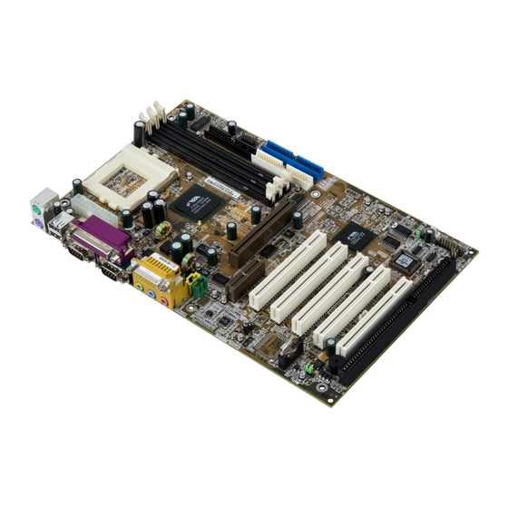
Page 8: Mainboard Layout
Chapter 1 Mainboard Layout Top : mouse Bottom: keyboard CPUFAN USB Ports Top : Parallel Port Bottom: COM A COM B D-LED JDLED Top : Game port Bottom: Line-Out Line-In CD_IN AUX_IN MODEM_IN Codec Creative CT5880 (Optional) BATT ISA Slot MS-6309 (V5.X) ATX VA Mainboard 694T AGP Slot... -
Page 9: Quick Components Guide
Quick Components Guide Component Function DIMM1~2 Installing SDRAM modules Socket 370 Installing CPU CPUFAN Connecting to CPUFAN SYSFAN Connecting to SYSTEM FAN ATX Power Supply Installing power supply IDE1& IDE2 Connecting to IDE hard disk drive FDD1 Connecting to floppy disk drive USB2 Connecting to USB interface PCI Slot 1~5... -
Page 10: Key Features
Chapter 1 Key Features ATX Form Factor CPU: Socket 370 for Intel family series and VIA Memory: 3 PC100/PC133 SDRAM DIMMs Vi/o & Vcore Adjustable USB PC to PC Networking Function (Optional) Support Optional D-Bracket™ Slot: 1 AGP slot, 1 AMR slot, 5 PCI slots, 1 ISA slot I/O: 2 serial ports, 1 parallel port, 4 USB ports, 1 floppy port, 1 IrDA connector, 1 Audio/Game port Support PCI 2.2... -
Page 11: Msi Special Features
MSI Special Features T.O.P Tech™ The T.O.P Tech rately detect the CPU’s temperature. You can find out the temperature on BIOS setup menu. The PC Alert CPU temperaure on Setup menu AMIBIOS SETUP - Hardware Monitor Setup (C)2001 American Megatrends, Inc. All Rights Reserved... -
Page 12: Pc Alert™ Iii
Chapter 1 PC Alert™ III The PC Alert III is an utility you can find in the CD-ROM disk. The utility is just like your PC doctor that can detect the following PC hardware status during real time operation: * monitor CPU & system temperatures * monitor fan speed(s) * monitor system voltage * monitor chassis intrusion... - Page 13 Introduction Features: Network Management - Monitoring & remote control Basic System Utilities - Scandisk & Defragment to maintain your HDD 3D Graphics Design - Enables a more friendly user interface Sofware Utilities - SoftCooler Optimized Cooling...
-
Page 14: D-Led™ & D-Bracket
These users can use the feature to detect if there are any problems or failures. If your motherboard installs an optional D-Bracket™ which also integrates four Diagnostic LEDs, definitions of the LED signals are the same as D-LED™ as shown below. - Page 15 Introduction D-LED D-Bracket Description Processor Initialization - This will show information regarding the processor (like brand name, system bus, etc…) Testing RTC (Real Time Clock) Initializing Video Interface - This will start detecting CPU clock, checking type of video onboard. Then, detect and initialize the video adapter. BIOS Sign On - This will start showing information about logo, processor brand name, etc….
-
Page 16: Fuzzy Logic™ Iii
Chapter 1 Fuzzy Logic™ III The Fuzzy Logic™ III utility allows users to overclock the CPU FSB (Front Side Bus) frequency in the Windows environment. Select the CPU frequency you prefer and click “Go” to apply the frequency or click “Save” allowing the system to run at the specified frequency each time when the system is powered on. -
Page 17: Chapter 2. Hardware Setup
C h a p t e r Hardware Setup This chapter provides you with the information about hardware setup procedures. While doing the installation, be careful in holding the compo- nents and follow the installation procedures. For some components, if you install in the wrong orientation, the components will not work properly. -
Page 18: Central Processing Unit: Cpu
Chapter 2 Central Processing Unit: CPU The mainboard supports Intel PGA2)/Tualatin (FC-PGA2) and VIA uses a CPU socket called Socket 370 for easy CPU installation. Make sure the CPU has a Heat Sink and a cooling fan attached on top to prevent overheating. -
Page 19: Cpu Core Speed Derivation Procedure
CPU Clock Core/Bus ratio then CPU core speed Overclocking This motherboard is designed to support overclockingo. However, please make sure your components are able to tolerate such abnormal setting, while doing overclocking. Any attempt to operate beyond product specifications is not recommended. -
Page 20: Memory Installation
Chapter 2 Memory Installation The mainboard provides 3 sockets for 168-pin, 3.3V SDRAM DIMM with 6 memory banks. To operate properly, at least one DIMM module must be installed. SDRAM Combination You can install the memory modules in any order and in any combination as listed below: D IM M S ocket S ocket 1... -
Page 21: Module Installation Procedures
Module Installation Procedures You can install single sided or double sided 168-pin DIMMs into DIMM slots according to your needs. 1. The DIMM slot has 2 Notch Keys “VOLT and DRAM”, so the DIMM memory module can only fit in one direction. 2. -
Page 22: Power Supply
Chapter 2 Power Supply The mainboard supports ATX power supply for the power system. Before inserting the power supply connector, always make sure that all compo- nents are installed properly to ensure that no damage will be caused. ATX 20-Pin Power Supply This connector allows you to connect to an ATX power supply. -
Page 23: Back Panel
Back Panel The Back Panel provides the following connectors: Mouse Keyboard Mouse Connector The mainboard provides a standard PS/2 ® for attaching a PS/2 mouse. You can plug a PS/2 connector. PS/2 Mouse (6-pin Female) Parallel COM A COM B ®... -
Page 24: Keyboard Connector
Chapter 2 Keyboard Connector The mainboard provides a standard PS/2 ® tor for attaching a PS/2 this connector. PS/2 Keyboard (6-pin Female) USB Connectors The mainboard provides a UHCI (Universal Host Controller Interface) Universal Serial Bus root for attaching USB devices such as keyboard, mouse or other USB-compatible devices. -
Page 25: Parallel Port Connector
Parallel Port Connector The mainboard provides a 25-pin female centronic connector for LPT. A parallel port is a standard printer port that supports Enhanced Parallel Port (EPP) and Extended Capabilities Parallel Port (ECP) mode. Pin Definition SIGNAL DESCRIPTION STROBE Strobe DATA0 Data0 DATA1... -
Page 26: Serial Port Connector: Com A & Com B
Chapter 2 Serial Port Connector: COM A & COM B The mainboard has two 9-pin male DIN connectors for serial port COM A and COM B. You can attach a serial mouse or other serial devices. 1 2 3 4 5 6 7 8 9 9-Pin Male DIN Connectors Joystick/Midi Connectors... -
Page 27: Connectors
Connectors The mainboard provides connectors to connect to FDD, IDE HDD, case, modem, LAN, USB Ports, IR module and CPU/System FAN. Floppy Disk Drive Connector: FDD The mainboard provides a standard floppy disk drive connector that supports 360K, 720K, 1.2M, 1.44M and 2.88M floppy disk types. Hardware Setup 2-11... -
Page 28: Hard Disk Connectors: Ide1 & Ide2
Chapter 2 Hard Disk Connectors: IDE1 & IDE2 The mainboard uses an IDE controller on the VIA that provides PIO mode 0-4, Bus Master, and Ultra DMA 33/66/100 modes. It has two HDD connectors IDE1 (Primary) and IDE2 (Secondary). You can connect up to four hard disk drives, CD-ROM or 120MB Floppy to IDE1 and IDE2. -
Page 29: Case Connector: Jfp1
Case Connector: JFP1 The case connector block JFP1 allows you to connect to the Power Switch, Reset Switch, Speaker, Power LED, and HDD LED on the case. Power Switch Connect to a 2-pin push button switch. Reset Switch Reset switch is used to reboot the system rather than turning the power ON/ OFF. -
Page 30: Speaker
Chapter 2 power LED changes its color to indicate different system states: GREEN color indicates full-on mode. ORANGE color indicates suspend/sleep mode. 3-pin dual color power LED: Connected to pin 4, 5 & 6. The 3-pin power LED changes its color to indicate different system states: GREEN color indicates full-on mode. -
Page 31: Wake On Ring Connector: Jmdm1
Wake On Ring Connector: JMDM1 This connector allows you to connect to a modem card with Wake On Ring function. The connector will power up the system when a signal is received through the modem card. Wake On LAN Connector: JWOL1 This connector allows you to connect to a LAN card with Wake On LAN function. -
Page 32: Irda Infrared Module Connector: J4
Chapter 2 IrDA Infrared Module Connector: J4 This connector allows you to connect to an IrDA Infrared module. You must configure the setting through the BIOS setup to use the IR function. Modem-In Connector: MODEM_IN The connector is for modem with internal audio connector. Mono_Out MODEM_IN Phone_In... -
Page 33: Cd-In Connector: Cd_In
CD-In Connector: CD_IN The connector is for CD-ROM audio connector. CD_IN Aux Line-In Connector: AUX_IN The connector is for DVD add-on card with Line-in connector. AUX_IN 2-17 Hardware Setup... -
Page 34: Fan Power Connectors: Cpufan/Sysfan
Chapter 2 Fan Power Connectors: CPUFAN/SYSFAN The CPUFAN (processor fan) and SYSFAN (system fan) support system cooling fan with +12V. It supports three-pin head connector. When connecting the wire to the connectors, always take note that the red wire is the positive and should be connected to the +12V, the black wire is Ground and should be connected to GND. -
Page 35: Usb Pc To Pc Connector: Usb2 (Optional)
USB PC To PC Connector: USB2 (Optional) The mainboard provides one USB (Universal Serial Bus) pin header that allows you to connect optional USB ports. USB2 is optionally imple- mented with USB PC to PC Networking function. Depending on the model you purchased, the mainboard may offer three USB 1.1 ports and one USB PC2PC port, or just four USB 1.1 ports. - Page 36 Chapter 2 Note: USB PC to PC Networking feature allows users to transfer and receive data from other computers or share system resources with other computers without using any network adapter. See below for instructions. To Attach the USB PC to PC cable 1.
- Page 37 4. Connect your PC to another PC via USB PC to PC cable. The transfer rate will run at USB 1.1 speed (12Mbps/s). Connect to the B Type Connector on your PC B Type Connector For more information on USB PC to PC Networking function, refer to Appendix A: USB PC to PC Networking Function.
-
Page 38: D-Bracket™ Connector: Jdled
Chapter 2 D-Bracket™ Connector: JDLED Your motherboard comes with JDLED connector and you can connect an optional D-Bracket™ to JDLED. D-Bracket™ is a USB Bracket integrating four LEDs whose functions are similar to D-LED™ and allows users to identify system problem through 16 various combinations of LED signals. For defini- tions of 16 signal combinations, refer to page 1-10 D-LED™... -
Page 39: Jumpers
Jumpers The motherboard provides one jumper for you to set the computer’s function. This section will explain how to change your motherboard’s function through the use of the jumper. Clear CMOS Jumper: JBAT1 There is a CMOS RAM on board that has a power supply from external battery to keep the data of system configuration. -
Page 40: Slots
Chapter 2 Slots The motherboard provides five 32-bit Master PCI Bus Slots, one AGP, one AMR and one ISA slot. AGP Slot AMR Slot PCI Slots ISA Slot AGP (Accelerated Graphics Port) Slot The AGP slot allows you to insert the AGP graphics card. AGP is an interface specification designed for the throughput demands of 3D graphics. -
Page 41: Isa Slot
the power supply first. Meanwhile, read the documentation for the expansion card to make any necessary hardware or software settings for the expansion card, such as jumpers, switches or BIOS configuration. ISA Slot The slot allows you to install ISA expansion card. PCI Interrupt Request Routing The IRQ, abbreviation of interrupt request line and pronounced I-R-Q, are hardware lines over which devices can send interrupt signals to the... - Page 42 ® ® ® ®...
- Page 43 Hit DEL if you want to run SETUP...
- Page 44 ®...
- Page 45 AMIBIOS SIMPLE SETUP UTILITY - VERSION 1.43 (C)2001 American Megatrends, Inc. All Rights Reserved Standard CMOS Features Advanced BIOS Features Advanced Chipset Features Power Management Setup PNP/PCI Configurations Integrated Peripherals Hardware Monitor Setup ESC : Quit F10 : Save & Exit Time, Date, Hard Disk Type,…...
- Page 46 ®...
- Page 48 ®...
- Page 50 ®...
- Page 51 ® ® ®...
- Page 52 ®...
- Page 54 ®...
- Page 56 ®...
- Page 58 ®...
- Page 60 ®...
- Page 62 ®...
- Page 64 ®...
- Page 66 ®...
- Page 68 AMIBIOS SIMPLE SETUP UTILITY - VERSION 1.43 (C)2001 American Megatrends, Inc. All Rights Reserved Standard CMOS Features Advanced BIOS Features Advanced Chipset Features Power Management Setup Load Fail-Safe Defaults(Y/N)? N PNP/PCI Configurations Integrated Peripherals Hardware Monitor Setup ESC : Quit F10 : Save &...
- Page 69 AMIBIOS SIMPLE SETUP UTILITY - VERSION 1.43 (C)2001 American Megatrends, Inc. All Rights Reserved Standard CMOS Features Advanced BIOS Features Advanced Chipset Features Power Management Setup Load Optimized Defaults(Y/N)? N PNP/PCI Configurations Integrated Peripherals Hardware Monitor Setup ESC : Quit F10 : Save &...
- Page 70 AMIBIOS SIMPLE SETUP UTILITY - VERSION 1.43 (C)2001 American Megatrends, Inc. All Rights Reserved Standard CMOS Features Advanced BIOS Features Advanced Chipset Features Power Management Setup PNP/PCI Configurations Enter new supervisor password: Integrated Peripherals Hardware Monitor Setup ESC : Quit F10 : Save &...
- Page 72 ® ½...
- Page 73 AMIBIOS SIMPLE SETUP UTILITY - VERSION 1.43 (C)2001 American Megatrends, Inc. All Rights Reserved Standard CMOS Features Advanced BIOS Features Advanced Chipset Features Power Management Setup SAVE to CMOS and EXIT(Y/N)? Y PNP/PCI Configurations Integrated Peripherals Hardware Monitor Setup ESC : Quit F10 : Save &...
- Page 74 AMIBIOS SIMPLE SETUP UTILITY - VERSION 1.43 (C)2001 American Megatrends, Inc. All Rights Reserved Standard CMOS Features Advanced BIOS Features Advanced Chipset Features Power Management Setup PNP/PCI Configurations Quit without saving(Y/N)? N Integrated Peripherals Hardware Monitor Setup ESC : Quit F10 : Save &...
-
Page 75: Entering Setup
AWARD BIOS Setup ® The mainboard uses AWARD ity for users to modify the basic system configuration. The information is stored in a battery-backed CMOS RAM so it retains the Setup information when the power is turned off. This chapter provides you with the overview of the BIOS Setup program. It contains the following topics: Entering Setup Control Keys... -
Page 76: Entering Setup
Chapter 4 Entering Setup Power on the computer and the system will start POST (Power On Self Test) process. When the message below appears on the screen, press <DEL> key to enter Setup. Hit DEL if you want to run SETUP If the message disappears before you respond and you still wish to enter Setup, restart the system by turning it OFF and On or pressing the RESET button. -
Page 77: Getting Help
Getting Help After entering the Setup utility, the first screen you see is the Main Menu. Main Menu The main menu displays the setup categories the BIOS supplies. You can use the arrow keys ( to select the item. The on-line description for the selected setup category is displayed on the bottom of the screen. -
Page 78: The Main Menu
Chapter 4 The Main Menu Once you enter Award BIOS CMOS Setup Utility, the Main Menu (Figure ® 1) will appear on the screen. The Main Menu allows you to select from ten setup functions and two exit choices. Use arrow keys to select among the items and press <Enter>... -
Page 79: Supervisor/User Password
Advanced Chipset Features Use this menu to change the values in the chipset registers and optimize your system’s performance. Integrated Peripherals Use this menu to specify your settings for integrated peripherals. Power Management Setup Use this menu to specify your settings for power management. PnP/PCI Configuration This entry appears if your system supports PnP/PCI. -
Page 80: Standard Cmos Setup
Chapter 4 Standard CMOS Setup The items in Standard CMOS Setup Menu are divided into 10 categories. Each category includes no, one or more than one setup items. Use the arrow keys to highlight the item and then use the <PgUp> or <PgDn>... - Page 81 Date The date format is <day><month> <date> <year>. Day of the week, from Sun to Sat, determined by BIOS. Read-only. month The month from Jan. through Dec. date The date from 1 to 31 can be keyed by numeric function keys. year The year, depends on the year of the BIOS Time...
-
Page 82: Advanced Bios Features
Chapter 4 Advanced BIOS Features CMOS Setup Utility - Copyright(C) 1984-2001Award Software Anti-Virus Protection CPU Internal Cache External Cache CPU L2 Cache ECC Checking Processor Number Feature Quick Power On Self Test First Boot device Second Boot device Third Boot device Boot other device Swap Floppy Drive Boot Up Floppy Seek... -
Page 83: Cpu Internal Cache
CPU Internal Cache Enabled Disabled Note: The internal cache is built in the processor. External Cache Choose Enabled or Disabled. This option enables the level 2 cache memory. CPU L2 Cache ECC Checking Choose Enabled or Disabled. This option enables the level 2 cache memory ECC(error check correction). -
Page 84: Boot Up Numlock Status
Chapter 4 Boot Up NumLock Status Keypad is numeric keys. Keypad is arrow keys. Gate A20 Option Normal Fast Typematic Rate Setting Key strokes repeat at a rate determined by the keyboard controller. When enabled, the typematic rate and typematic delay can be selected. The settings are: Enabled/Disabled. - Page 85 ® AWARD BIOS Setup OS Selection for DRAM > 64MB Allows OS2 to be used with > 64 MB of DRAM. Settings are Non- ® OS/2 and OS2. Set to OS/2 if using more than 64MB and running OS/2 ® 4-11...
-
Page 86: Advanced Chipset Features
Chapter 4 Advanced Chipset Features The Advanced Chipset Features Setup option is used to change the values of the chipset registers. These registers control most of the system options in the computer. Choose the “ADVANCED CHIPSET FEATURES” from the Main Menu and the following screen will appear. -
Page 87: Dram Clock
DRAM Clock The chipset support synchronous and asynchronous mode between the host clock and DIMM clock. Host CLK Memory Hole In order to improve performance, certain space in memory can be reserved for ISA cards. This memory must be mapped into the memory space below 16 MB. -
Page 88: Cpu To Pci Write Buffer
Chapter 4 warded to the AGP without any translation. AGP-4X Mode This item is used to Enabled or Disabled the AGP support for AGP 4x mode. CPU to PCI Write Buffer When this field is Enabled, writes from the CPU to the PCI bus are buffered, to compensate for the differences between the CPU and the PCI bus. -
Page 89: Integrated Peripherals
Integrated Peripherals CMOS Setup Utility - Copyright(C) 1984-2001 Award Software Onchip IDE Channel0 Onchip IDE Channel1 IDE Prefetch Mode Primary Master PIO Primary Slave PIO Secondary Master PIO Secondary Slave PIO Primary Master UDMA Primary Slave UDMA Secondary Master UDMA Secondary Slave UDMA Init Display First Onchip USB... -
Page 90: Init Display First
Chapter 4 Primary/Secondary Master/Slave PIO The four IDE PIO (Programmed Input/Output) fields let you set a PIO mode (0-4) for each of the four IDE devices that the onboard IDE interface supports. Modes 0 through 4 provide successively increased performance. In Auto mode, the system automatically determines the best mode for each device. -
Page 91: Onboard Parallel Port
of block read/writes per sector the drive can support. The settings are: Enabled, Disabled. Onboard FDD Controller Select Enabled if your system has a floppy disk controller (FDD) installed on the system board and you wish to use it. If you install add-on FDC or the system has no floppy drive, select Disabled in this field. -
Page 92: Ecp Mode Use Dma
Chapter 4 Onboard Parallel Mode SPP : Standard Parallel Port EPP : Enhanced Parallel Port ECP : Extended Capability Port To operate the onboard parallel port as Standard Parallel Port only, choose “SPP.” To operate the onboard parallel port in the ECP and SPP modes simultaneously, choose “ECP/SPP.”... -
Page 93: Power Management Setup
Power Management Setup The Power Management Setup allows you to configure you system to most effectively save energy while operating in a manner consistent with your own style of computer use. CMOS Setup Utility - Copyright(C) 1984-2001 Award Software IPCA Function Power Management ACPI Suspend Type PM Control by APM... -
Page 94: Power Management
Chapter 4 Power Management This category allows you to select the type (or degree) of power saving and is directly related to the following modes: HDD Power Down Doze Mode Suspend Mode There are three selections for Power Management, two of which have fixed mode settings. -
Page 95: Pm Control By Apm
PM Control by APM System BIOS will ignore APM when power managing the system. System BIOS will wait for APM’s prompt before it enter any PM mode Note :Enable this for O.S. with APM like Windows Video Off Option The settings are N/A, Standby, Doze, or Suspend. This option is for choosing the setting in which the monitor will turn off. -
Page 96: Power Failure
Chapter 4 State After Power Failure This option will determine how the system will power on after a power failure. LED In Suspend This item determines which state the Power LED will use. The settings are Blink, Dual color, and Single color. Blink Power LED will blink when the system enters the suspend mode. -
Page 97: Rtc Alarm Resume
LPT & COM I/O Access When On of LPT & COM, any activity from one of the listed system peripheral devices or IRQs wakes up the system HDD & FDD I/O Access When On of HDD & FDD, any activity from one of the listed system peripheral devices or IRQs wakes up the system PCI Master When On of PCI Master, any activity from one of the listed system... -
Page 98: Irqs Activity Monitoring
Chapter 4 IRQs Activity Monitoring IRQ3 (COM 2) IRQ4 (COM 1) IRQ5 (LPT 2) IRQ6 (Floppy Disk) IRQ7 (LPT 1) IRQ8 (RTC Alarm) IRQ9 (IRQ2 Redir) IRQ10 (Reserved) IRQ11 (Reserved) IRQ12 (PS/2 Mouse) IRQ13 (Coprocessor) IRQ14 (Hard Disk) IRQ15 (Reserved) Move Enter:Select +/-/PU/PD:Value F10:Save ESC:Exit F1:General Help F5:Previous Values F6:Fail-safe defaults F7:Optimized Defaults The following is a list of IRQ’s, Interrupt ReQuests, which can be exempted... -
Page 99: Pnp/Pci Configuration Setup
PnP/PCI Configuration Setup This section describes configuring the PCI bus system. PCI, or Personal Computer Interconnect, is a system which allows I/O devices to operate at speeds nearing the speed the CPU itself uses when communicating with its own special components. This section covers some very technical items and it is strongly recommended that only experienced users should make any changes to the default settings. -
Page 100: Reset Configuration Data
Chapter 4 Reset Configuration Data Normally, you leave this field Disabled. Select Enabled to reset Extended System Configuration Data (ESCD) when you exit Setup if you have installed a new add-on and the system reconfiguration has caused such a serious conflict that the operating system can not boot. The settings are: Enabled and Disabled . -
Page 101: Pc Health Status
This section helps you to get more information about your system including CPU temperature, FAN speed and voltages. It is recommended that you contact with your motherboard supplier to get proper value about your setting of the CPU temperature. CMOS Setup Utility - Copyright(C) 1984-2001 Award Software Current CPU Temp. -
Page 102: Frequency/Voltage Control
Chapter 4 Frequency/Voltage Control This section is for setting the CPU Frequency/Voltage Control. CMOS Setup Utility - Copyright(C) 1984-2000 Award Software CPU Clock Ratio Auto Detect DIMM/PCI CLk CPU Host Clock (CPU/PCI) Move Enter:Select +/-/PU/PD:Value F10:Save ESC:Exit F1:General Help F5:Previous Values F6:Fail-safe defaults F7:Optimized Defaults CPU Clock Ratio This item allows you to select the CPU clock ratio. -
Page 103: Load Fail-Safe/Optimized Defaults
Load Fail-Safe/Optimized Defaults Load Fail-Safe Defaults When you press <Enter> on this item, you get a confirmation dialog box with a message similar to: Load Fail-Safe Defaults (Y/N) ? N Pressing ‘Y’ loads the BIOS default values for the most stable, minimal- performance system operations. -
Page 104: Chapter 5. Installing Drivers
Chapter 4. Installing Drivers Installing VIA Chipset Drivers The chapter describes how to install the VIA chipset , AC97 and op- tional Creative CT5880 audio drivers, and the basic system requirements. Note: You must install VIA chipset driver before installing other drivers like audio or VGA drivers. -
Page 105: Overview
Chapter 5 Overview The 694T Pro (MS-6309 v5.X) is paired with the VIA Pro133A chipset. Highly advanced, the chipset combines an integrated 2D/ 3D engine with DVD hardware acceleration, AC-97 audio support for SoundBlaster Pro and FM synthesis legacy audio. - Page 106 Driver Installation for Windows Installing VIA® Chipset Driver 1. Insert the supplied CD disk into the CD-ROM drive. 2. The CD will auto-run and the setup screen will appear. 3. Click on Via Chipset Drivers and the screen will show VIA Service Pack 4.XX.
- Page 107 Chapter 5 2. Go to My Computer and double click on the CD-ROM icon. The setup screen will appear again. 3. Click on Creative PCI 128 Sound Drivers. 4. The setup program will request you to Remove and Install Software or Remove Only.
- Page 108 Driver Installation for Windows Note: Before installing VIA chipset driver, you should installing Windows 2000 Service Pack2 or the latest version. Installing VIA® Chipset Driver 1. Insert the supplied CD disk into the CD-ROM drive. 2. The CD will auto-run and the setup screen will appear. 3.
- Page 109 Chapter 5 screen will appear again. 3. Click on VIA AC97 PCI Sound Drivers and the screen will show VIA AC97 PCI Sound Drivers. 4. Click Next to proceed and the screen will show Install or Uninstall. Select Install and then click on Next. 5.
- Page 110 Driver Installation for Windows Installing VIA® Chipset Driver 1. Insert the supplied CD disk into the CD-ROM drive. 2. The CD will auto-run and the setup screen will appear. 3. Click on Via Chipset Drivers and the screen will show VIA Service Pack 4.XX.
- Page 111 Chapter 5 One Touch Setup: ® In Windows ME, you probably will see the One Touch Setup button appear on the setup screen. Choosing the button will help you install more than one driver into the system without going through the installation process step by step and save a lot of time.
- Page 112 Driver Installation for Windows ® Note: Install Windows VIA drivers into Windows Installing VIA® Chipset Driver 1. Insert the provided CD disk into the CD-ROM drive. 2. The CD will auto-run and the setup screen will appear. 3. Click on VIA Chipset Drivers and the screen will show VIA Service Pack 4.XX.
- Page 113 Chapter 5 driver for the Microsoft Sidewinder 3D Pro Joystick?” Please click No to continue. 8. Please click Finish to restart your computer and complete installation. Installing Creative CT5880 Sound Driver (Optional) 1. Make sure the supplied CD disk is in the CD-ROM drive. 2.
-
Page 114: Appendix A: Usb Pc To Pc Networking Function
Appendix A: USB PC to PC Networking Function USB PC to PC Networking Function USB PC to PC is the best solution for providing the easiest network connection service to you. By connecting multiple PCs through USB PC to PC port, you can build up a local area network without any network adapter. We give this Ethernet emulation environment a name —... -
Page 115: Installing Genelink™ Lan Driver
Appendix A Installing GeneLink™ LAN Driver Before you use the function, you need to install the GeneLink™ LAN Driver to all PCs connected via USB PC to PC cables. Step 1. Installing driver 1. Insert the driver CD and click “USB PC to PC” button to install the driver. 2. - Page 116 Notice: 1. You should use the same network protocol (TCP/IP, NetBEUI or IPX) for connecting GeneLink 2. If you’ve already configured your [IPX/SPX] and [Client for Netware Networks] before installing GeneLink that you should also install Software Router while installing GeneLink driver into your system.
-
Page 117: Using Usb Pc To Pc Networking Function
Appendix A Using USB PC to PC Networking Function How to share your files, folders, drives and printers Go to the file, folder, drive or printer that you want to share. Right click your mouse pointer on the resource you want to share, you’ll see a POP-UP Menu. - Page 118 In “Sharing” tag, select “Share As”. Enter a name to help others recognize your sharing file or device (optional). Select “Access Type”. If you select “ Depend on Password”, your need to assign an access password for this device. Click “OK” button. How to check if you have already shared your resources Go to the resource and check if Windows had added a hand on its icon or not.
- Page 119 Appendix A Connecting to Internet through USB PC to PC & Office/Home LAN If you would like to access Internet resources through USB PC to PC, here are some things you should notice: You must define which computer should install GeneLink Software Router.
- Page 120 USB PC to PC Networking Function - Click on “Properties”, you’ll see another menu. - Choose TCP/IP in Configuration tag, and then press “Proper- ties” button. You’ll see “TCP/IP Properties” menu.
- Page 121 Appendix A - Now you need to navigate between “IP Address”, “Gateway”, and “DNS Configuration” tags to specify “IP Address”, “Subnet Mask”, “Gateway” and “DNS Server”. If you don’t know their values, pleases consult your Network Administrator. - Press “OK” button to go back to “Network” pop-up menu. Choose “Identification”...
- Page 122 USB PC to PC Networking Function SPECIAL NOTICE for those users who have already installed Network Adapter in their system: If you’ve already configured your [IPX/SPX] and [Client for Netware Networks] before installing GeneLink driver, we strongly recommend that you should also install Software Router when you install GeneLink driver into your system.
- Page 123 Appendix A Connecting to internet through USB PC to PC & remote modem If there is no existing Office/Home LAN and your computer does not have a modem, you still can connect USB PC to PC to internet through another computer with a modem installed.
- Page 124 “Communications”. The “Communications” window appears. Check “Internet Connection Sharing” and click “OK”. The “Home Networking Wizard” starts. Click “Next”. USB PC to PC Networking Function A-11...
- Page 125 Appendix A Click “Adirect connection to my ISP using the following device”, and select “GeneLink Network Adapter” from the pull- down menu. Click “Next”. Note: For the computer with a modem installed, you need to select “My Connection” instead of “GeneLink Network Adapter”...
- Page 126 Click “Finish.” Restart the computer. Note: In Windows® 98SE, you can access internet through the shared connection of another computer, but it is unable for you to control the remote modem. However, in Windows® ME, you are allowed to dial the remote modem of another computer using the dialing program built in Windows®.