Datalogic DS2100N Quick Reference Manual
Datalogic compact laser scanner quick reference guide
Hide thumbs
Also See for DS2100N:
- Brochure & specs (2 pages) ,
- Reference manual (119 pages) ,
- Reference manual (106 pages)
Table of Contents
Advertisement
QUICK REFERENCE GUIDE
2
1
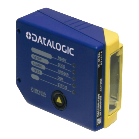
Warning and Device Class Labels
1
2
"POWER ON" LED
Mounting Holes
3
4
"READY" LED
"GOOD" LED
5
"TRIGGER" LED
6
This manual illustrates a Stand Alone application. For other types of installations, such as
ID-NET™, Pass-Through, Multiplexer Layout, etc. and for a complete scanner configuration using
Genius™ configuration program, refer to the DS2100N Reference Manual available on the CD.
This manual is also downloadable from the Web at www.automation.datalogic.com/ds2100n.
NOTE
DS2100N
3
11
Figure A
Laser Beam Output Window
7
"COM" LED
8
"STATUS" LED
9
Push Button
10
Accessory Mounting Holes
11
4
5
6
10
9
8
7
Advertisement
Table of Contents

Related Manuals for Datalogic DS2100N


Summary of Contents for Datalogic DS2100N
- Page 1 This manual illustrates a Stand Alone application. For other types of installations, such as ID-NET™, Pass-Through, Multiplexer Layout, etc. and for a complete scanner configuration using Genius™ configuration program, refer to the DS2100N Reference Manual available on the CD. This manual is also downloadable from the Web at www.automation.datalogic.com/ds2100n.
-
Page 2: Updates And Language Availability
UPDATES AND LANGUAGE AVAILABILITY The latest drivers and documentation updates for this product are available on Internet. Su Internet sono disponibili le versioni aggiornate di driver e documentazione di questo prodotto. Questo manuale Les versions mises à jour de drivers et documentation de ce produit sont disponibles sur Internet. Ce manuel est Im Internet finden Sie die aktuellsten Versionen der Treiber und Dokumentation von diesem Produkt. -
Page 3: Step 1 - Connect The System
P.S. CBX100/500 Pinout for DS2100N The table below gives the pinout of the CBX100/500 terminal block connectors. Use this pinout when the DS2100N reader is connected by means of the CBX100/500: Power Power Supply Input Voltage + Power Supply Input Voltage -... - Page 4 25-pin Connector Pinout for DS2100N The table below gives the pinout of the 25-pin male D-sub connector for connection to the power supply and input/output signals. Use this pinout when the DS2100N reader is connected by means of the 25-pin connector: Name...
-
Page 5: Step 2 - Mount And Position The Scanner
STEP 2 – MOUNT AND POSITION THE SCANNER To mount the DS2100N, use the mounting bracket to obtain the most suitable position for the reader as shown in the figures below. Tilt Skew When mounting the DS2100N take into consideration these three ideal label position angles:, Skew 10° to 30°, Tilt 0°... -
Page 6: Step 3 - X-Press™ Configuration
STEP 3 – X-PRESS™ CONFIGURATION X-PRESS™ is the intuitive Human Machine Interface designed to improve ease of installation and maintenance. Status and diagnostic information are clearly presented by means of the five colored LEDs, whereas the single push button gives immediate access to the following relevant functions: •... - Page 7 Exit the process by pressing the X-PRESS™ push button once. The scanner will restart at the end of the process, and then the detected barcodes are automatically configured in scanner memory. If the barcode cannot be read because of low contrast or excessive ambient light, you can perform the AutoSetup function to optimize the optical parameters.
-
Page 8: Step 4 - Install Genius™ Configuration Program
STEP 4 – INSTALL GENIUS™ CONFIGURATION PROGRAM ™ Genius is a Datalogic scanner configuration tool providing several important advantages: • Wizard approach for new users; • Multi-language version; • Defined configuration directly stored in the reader; • Communication protocol independent from the physical interface allowing to consider the reader as a remote object to be configured and monitored. - Page 9 Barcode selection and definition Digital Outputs configuration The On Line operating Mode requires the reader to be connected to an External Trigger/Presence Sensor using I1A and I1B inputs. The Automatic operating mode does not require connection to an external Presence Sensor. When working in this mode the reader is continuously scanning, while the reading phase is activated each time a barcode enters the reader reading zone.
- Page 10 After defining the parameter values the following window appears allowing to complete the reader configuration as follows: • Saving the configuration to disk; • Switching to Advanced mode; Sending the configuration to the scanner. • After sending the configuration to the scanner you have completed the configuration process. By clicking Finish, the System Information window will be displayed with specific information concerning the scanner.
-
Page 11: Step 5 - Test Mode
STEP 5 – TEST MODE Use a code suitable to your application to test the system. Alternatively, you can use the Datalogic Test Chart (Interleaved 2/5 or Code 39). Enter the Test mode function by holding the X-PRESS™ push button pressed until the TEST LED is on. Release the button to enter the Test mode function. -
Page 12: Advanced Scanner Configuration
If you need to install a Pass-Through network refer to the DS2100N Reference Manual. • If you need to install a Multiplexer network refer to the DS2100N Reference Manual. • If you need to install an RS232 Master/Slave (for backward compatibility) refer to the DS2100N Reference Manual. -
Page 13: Reading Diagrams
*Reading Conditions = Standard *Scan Speed = 500 scans/sec * Parameter selectable in Genius™ (0,0) corresponds to the scanner output window DS2100N-1200 (Standard Resolution) 80 100 120 140 160 180 200 220 240 260 0.20 mm (8 mils) (mm) DS2100N-2200 (High Resolution) 20 30 0.15 mm... - Page 14 DS2100N-1204 High Performance (Standard Resolution) CONDITIONS Optic Version = Linear Code = Interleaved 2/5 Code 39 PCS = 0.90 Pitch angle = 0° Skew angle = 15° Tilt angle = 0° *Code Resolution: High - for 0.30 mm (12 mils) codes and smaller Standard - for 0.50 mm (20 mils)
-
Page 15: Reading Performance
READING PERFORMANCE Version Reading Distance 1XX0 40 mm (1.6 in) - 300 mm (11.8 in) on 0.50 mm (20 mils) codes 1XX4 50 mm (1.8 in) - 310 mm (11.8 in) on 0.50 mm (20 mils) codes 2XX0 30 mm (1.2 in) - 90 mm (3.5 in) on 0.30 mm (12 mils) codes 2XX4 45 mm (1.8 in) - 100 mm (3.9 in) on 0.20 mm (8 mils) codes TECHNICAL FEATURES... -
Page 16: Mechanical Dimensions
The quote refers to the scan line 20° Figure 11 – Mounting Bracket Overall Dimensions 3.31 0.16 DS2100N READY GOOD SETUP TRIGGER LEARN TEST STATUS PRESS INTERFACE Figure 10 – DS2100N Overall Dimensions 14.7 0.58 M 4 n° 4 90°... -
Page 17: Laser Safety
COMPLIANCE LASER SAFETY This product conforms to the applicable requirements of IEC 60825-1 and complies with 21 CFR 1040.10 except for deviations pursuant to Laser Notice N° 50, date June 24, 2007. The scanner is classified as a Class 2 laser product according to IEC 60825-1 regulations. Disconnect the power supply when opening the device during maintenance or installation to avoid exposure to hazardous laser light. - Page 18 DS2100N QUICK GUIDE PATENTS This product is covered by one or more of the following patents: U.S. patent: 5,992,740 European patent: 789,315 B1...
-
Page 19: Declaration Of Conformity
Gerät declare que el DS2100N Laser Scanner; sono conformi alle Direttive del Consiglio Europeo sottoelencate: are in conformity with the requirements of the European Council Directives listed below: sont conformes aux spécifications des Directives de l'Union Européenne ci-dessous: der nachstehend angeführten Direktiven des Europäischen Rats:...